Taramp's HV 40.000 CHIPEO User manual

Instruction manual
Manual de instrucción

Index
Term of warranty
Technical assistance
For international support, check on our website:
Phones: +55 18 3266-4050 / +55 18 99749-3391
E-mail: ser[email protected]
www.taramps.com.br/en/rede-de-assistencias-tecnicas or contact direct the factory support:
01
•Costs involving uninstallation, reinstallation of equipment as well as shipment to the factory;
•Tamper or torn warranty seal;
This warranty excludes:
•Cases in which the product is not used in adequate conditions;
•Defects caused by accessories, modifications or features attached to the product;
•The product with damage from falling, bumps or nature related problems (flooding, lightning, etc.);
•Warranty card is not properly filled or torn;
•Damage of any kind, due to problems in the product, as well as losses caused by discontinued use of the
product.
•Damaged products by improper installation, water infiltration, violation by unauthorized individuals;
TARAMPS, located on Abilio Daguano Street 274, Res. Manoel Martins – Alfredo Marcondes, SP - Brazil, ZIP
CODE 19180-000, guarantees this product against any defects on terms of project, making, assembling,
and/or with solidarity, due to project vices which cause it improper or inadequate to its original use within
12 months from the date of purchase. In case of defect during the warranty period, TARAMPS responsibility
is limited to the repairing or substitution of the device of its own making.
01 • Term of warranty
• Technical assistance
02 • Introduction
03 • Installation procedure
04 • Functions & inputs
• Key recommendations
• LEDs indicators / protections
08 • Examples of connections
09 • Technical features
07 • Charging the battery bank
06 • Interconnections
05 • Outputs & power supply connector

For questions, please call +55 (18) 3266-4050 or visit www.taramps.com.br.
It was developed in a modern laboratory and with the latest technology.
Congratulations on your purchase of a Taramps product.
This manual covers all features, operations and instructions to solve any doubt that may arise
during the installation. Please take some time to read it carefully in order to ensure the proper
installation and the use of all benefits this product can offer.
1 - Read this instruction manual carefully before carrying out any connection;
3 - It is compulsory to install fuses to protect against overloading. The fuse or circuit breaker
must be installed as close as possible to the battery and sized up according to the amplifier;
5 - Amplifier must be installed in a firm and ventilated area;
2 - Check carefully the polarity of power supply wiring (battery's positive and negative
terminals) loudspeakers and the minimum speaker impedance;
You can find below some key recommendations to get the most out of your amplifier:
Any connection to the amplifier input or output must be carried out when amplifier is
off;
4 - The gauge of power supply wiring is extremely important both to reach the desired
amplifier output and to the amplifier's safety. Use the wire gauge recommended in this
manual (page 06). Using wire gauges below the specified value will result in power loss and
overheating of cables. It is important that the power supply cables are the shortest possible;
7 - High power amplifiers have higher current consumption and require the installation of
additional batteries;
8 - Do not use any connector, or original vehicle power cable to install this system;
6 - In order to avoid interferences, the signal cable (RCA) must be away from the original wiring
of vehicle or from any other power supply cable;
9 - It is expressly forbidden to move the vehicle with this sound system in operation;
10 - Avoid children when installing and recharging the system. "No high voltage point should
be exposed after the installation has finished".
02
Taramps reserves the right to modify the contents of this document at any time without prior notice and does
not have the obligation to apply the changes in units which were previously produced.
Key recommendations
Introduction

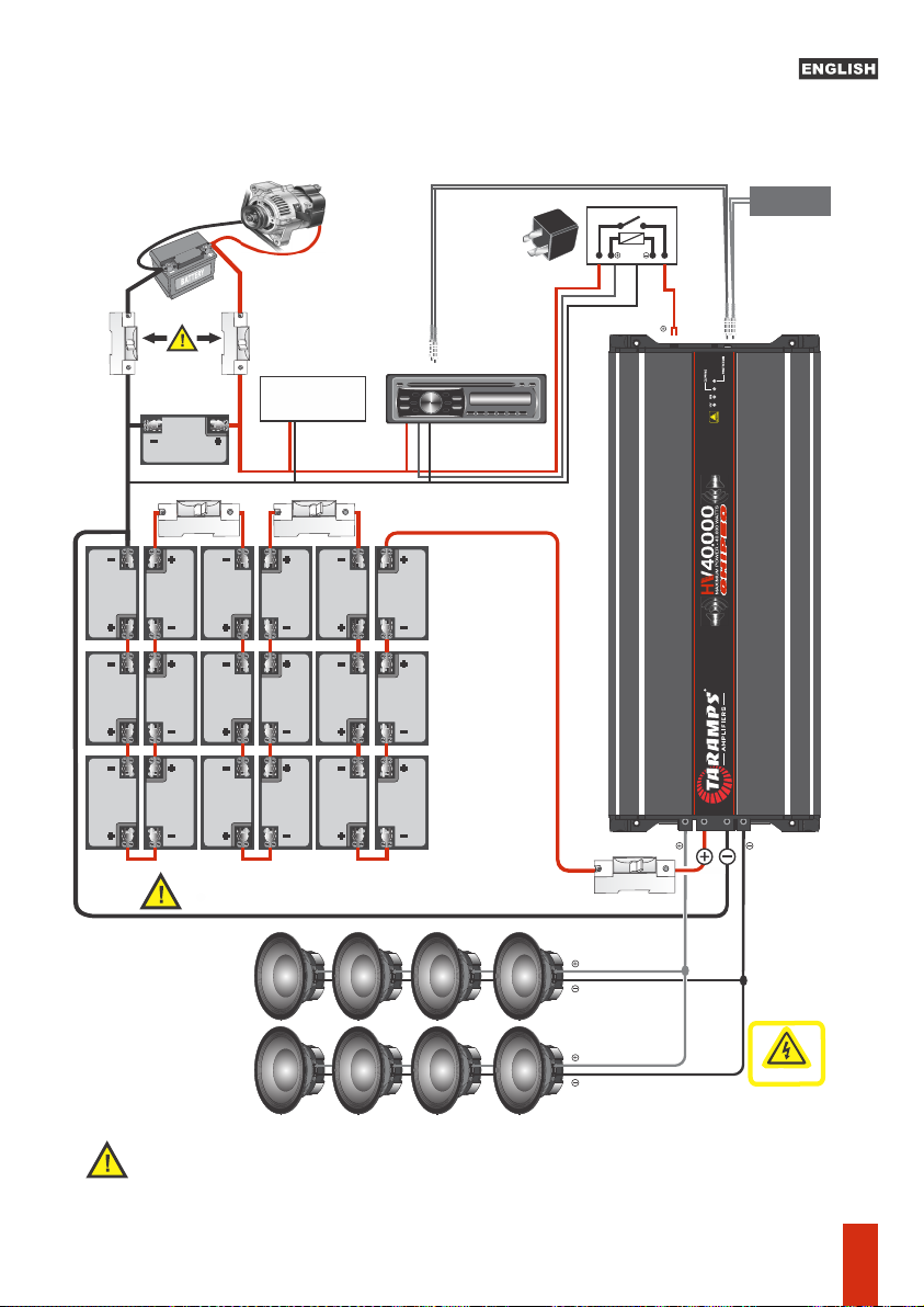
2 - Check carefully if the negative points of high voltage batteries bank and 12.6 VDC battery
negative point are connected together;
"Your life is valuable. Avoid accidents. Depending on the severity of an electric shock, it can
cost your life".
7 - After checking the preamplifier, disconnect the remote, activate the circuit breakers and
turn-on the remote again;
3 - Insulate completely all system connections, this avoiding electrical contact with the
vehicle chassi;
6 - The batteries must be insulated once installed, to avoid electric shock, sparks and/or
damage to vehicle;
1 - Check that any system is not shorted or in contact with the chassis of the vehicle;
CARING OF YOUR SOUND SYSTEM
3 - Do not connect the battery charger with the sound system in operation;
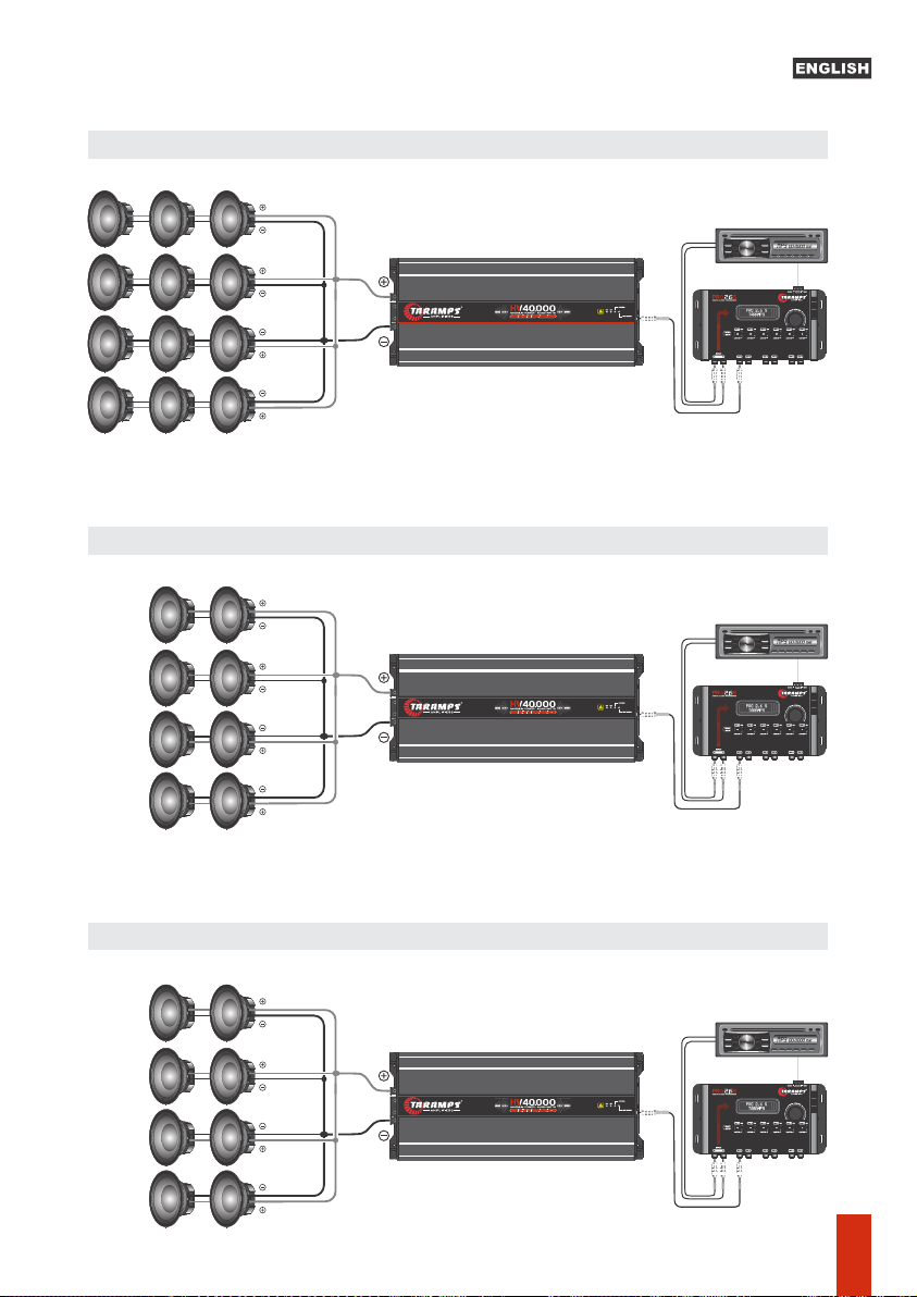
4 - Accessories and peripherals (such as Head Units, equalizers, crossover or other equipment
requiring power at 12 volts) should be eliminated from the original vehicle connections. The
equipment will be supplied by the of auxiliary batteries bank, designed according to system
needings;
1 - After the use of the sound system, turn off all circuit breakers;
6 - Turn on the remote to activate the preamp;
5 - Do not start the vehicle engine with the sound system in operation;
Failure to comply with any of the above procedures fully exempts Taramps from any liability
for the risks of its use. So for you can take advantage of this high technology, high quality and
powerful amplifier, be sure to follow step by step all safety procedures, otherwise it could
implies the loss of warranty.
For further information please contact our Technical Department to solve all doubts.
TURNING ON THE AMPLIFIER
2 - If you do not follow the proper procedures by qualified professionals, Taramps is exempled
of any responsibility;
7 - All connections should be made with all circuit breakers off.
4 - Make sure that your batteries are properly charged;
5 - Keep the volume control (Level) at the minimum;
1 - Follow all procedures described below;
5 - Circuit breakers must be installed in a visible and easily access place for operating, and
system maintenance;
8 - Set all volume settings, frequency cuts and enjoy all the advantages of your new amplifier.
2 - Never move the vehicle with activated circuit breakers;
4 - Do not add any other battery charger; Use only the specified charger.
3 - Connect the speakers in its output;
6 - The engine starting (ignition) is only allowed once all circuit breakers are turned off.
NOTE:
All electrical and electronic equipment installation must be made by qualified and trained
professionals.
Installation Procedure
03

Functions & input
LEVEL
MAX.
012VDC
INPUT
13
255
4
LEDS indicators / protections
3 - LEVEL: Adjust the sensitivity of the amplifier input, in order to get better performance and
volume.
1 - INPUT UNBAL: Connect to the RCA output of the Head Unit using good quality shielded
cables to avoid noise pickup. The signals from the L and R inputs are mixed (added) internally.
5 - FANS: HV 40.000 has four internal ventilation coolers, which can not be blocked. For
perfect operation, the amplifier must be installed in a cool and dry place. We recommend not
embedding it, so that air can circulate throughout the inside of the product, thus preventing
the thermal shutdown.
4 - 12.6 VDC POSITIVE TERMINAL (1.5A): Use an exclusive 12.6V battery and relay (driven by
the remote signal from Head Unit. See diagram at the page 06) .
2 - THRU OUT: This output (L and R) can send the same input signal (INPUT) to another
amplifier.
GREEN LED (HV): Indicates high voltage presence at the power terminals.
BLUE LED (ON): Indicates powered amplifier.
YELLOW LED (CLIPPING): Indicator of clipping and protections. (See
protections below).
RED LED (PROTECTION): Indicator of protections. (See protections
below).
LOW VOLTAGE (HV): Blue LED alternating with yellow.
SHORT: Red LED on.
HIGH VOLTAGE (HV): Blue LED alternating with red.
TEMPERATURE: Flashing yellow LED.
Voltage 12V
LOW VOLTAGE 12V: If the voltage is less than 9VDC, red LED flashes 2x.
HIGH VOLTAGE 12V: If the voltage exceeds 16VDC, red LED flashes 3x.
MISSING (HV): Blue LED blinking.
04

HIGH VOLTAGE
POWER
SPEAKER SPEAKER
1 2 3455
5 - FANS: HV 40,000 has four internal ventilation fans, which can not be blocked. For perfect
operation, the amplifier must be installed in a cool and dry place. We recommend not
embedding it, so that air can circulate throughout the inside of the product, thus preventing
the thermal shutdown.
4 - SPEAKER -: Output connector negative for loud speakers.
1 - SPEAKER +: Output connector positive for loud speakers.
3 - POWER -: Negative power input for high voltage.
2 - POWER +: Positive power input for high voltage.
We recommend using of well insulated tools.
Cables and circuit breakers should be good quality with its connections well protected and
insulated following the specified gauge.
The wiring gauge recommended described in scheme on page 06.
Please note: This is a device that will be high voltage powered. As in any electronic
equipment take care to not cause any incident during installation.
Wrongly dimensioned wiring may degrade the amplifier performance and causes power loss,
wiring heating and serious risk of fire.
Functions outputs & power input
21+Maximum care should be taken to avoid personal injury while
installing or operation the amplifier.
This product is powered by HIGH VOLTAGE. Risk of electric shock.
Danger of Death.
The sale, purchasing or installation of this product by those under 21 years
age is forbidden.
05

Attention! Do not use the vehicle chassis as system grounding point.
Is forbidden the locomotion of the vehicle with this in sound system in operation. For maximum power
and amplifier performance , use 18 x 130 amps batteries at least.
Installing one or more batteries is necessary to work at 12.6 Volts, to supply the pre amplifier
and other equipment that require this same voltage as Head Unit, crossover, equalizers,
amplifiers, etc. As shown in the scheme .
Interconnections
12 VDC
NEGATIVE
REMOTE
OUTPUT
FRONT/REAR (L/R)
2.5mm²
Mp3 00:0000 032
IT IS MANDATORY INSTALLATION OF
CIRCUIT BREAKER - 130A
(?)mm²
12.6 VDC
21mm²21mm²
21mm²
21mm²
. CROSSOVER;
. EQUALIZER
. AMPLIFIER - 12.6VDC
. ETC...
CIRCUIT BREAKER
60A
CIRCUIT BREAKER
60A
12.6 VDC12.6 VDC12.6 VDC
12.6 VDC 12.6 VDC 12.6 VDC
12.6 VDC12.6 VDC12.6 VDC
CIRCUIT BREAKER
130A CIRCUIT BREAKER
130A
To avoid electrical shock in the
bodywork of the vehicle, it is
extremely turn off the two
c ir cu i t b r ea ke rs b ef o re
c o nn e c t in g t he s y s te m
batteries in the HIGH VOLTAGE
series. Turn on them again only
when all system is turned off.
Cable RCA
Taramps
VEHICLE
ALTERNATOR
POWER BATTERY
HEAD UNIT AND
PRE AMPLIFIER
VEHICLE
ORIGINAL BATTERY
* Gauge for the output cable is 21mm², calculated a maximum length of 2m.
THRU OUT (L/R)
REMOTE
PRE AMP.
12.6 VDC
RELÉ 10A
2.5mm²
21mm²
21mm²
INPUT (L/R)
HIGH VOLTAGE
Amplificador
2
Amplificador
2
21mm²
21mm²
Entrada
Balanceada
CIRCUIT BREAKER
130A
illustrative images
06

The 15 A battery charger isn’t included .
As an example in the images we indicate
the source of 15A Taramps.
It is expressly mandatory to use a 15A fuse
in the positive output of each battery.
Are fully charged, we recommend that you
use individual sources for each battery.
In order for the battery bank in series.
12.6 VDC12.6 VDC12.6 VDC12.6 VDC12.6 VDC12.6 VDC
12.6 VDC 12.6 VDC 12.6 VDC 12.6 VDC 12.6 VDC 12.6 VDC
12.6 VDC12.6 VDC12.6 VDC12.6 VDC12.6 VDC12.6 VDC
DISJUNTOR - 130A
DISJUNTOR - 130A
DISJUNTOR - 130A
12.6 VDC
FOR POWER(S)
AMPLIFIER(S)
IT IS MANDATORY INSTALLATION OF
CIRCUIT BREAKERS (DC)
IT IS MANDATORY INSTALLATION OF
CIRCUIT BREAKERS - 130A (DC)
HIGH VOLTAGE
Charging the battery bank
07

Examples of connections:
Connection 12 Speakers 8 OHMS
Connection 8 Speakers 4 OHMS
Connection 8 Speakers 2 OHMS
Illustrative images
Head Unit
Illustrative images
Head Unit
Illustrative images
Head Unit
08

Technical features
Short-Circuit to Output, Short on output compared to GND, Low
impedance at output, High/Low supply voltage and Thermal
protection**
227VDC @ 0.5 Ohm - 18 Batteries
>95dB
1
40.000W RMS
330mV ( Level 100%) @ 0.5 Ohm
0.3%
10Hz ~ 15KHz (0.5dB)
92% @ 0.5 Ohm (at Maximum Power)
27K Ohms
110mA
91.5A
228 x 64 x 561mm / 8.98" x 2.52" x 22.07"
5.70Kg / 12.54lb
183A
275VDC
140VDC
Number of channels:
Efficiency:
Protection system:
Maximum supply voltage:
Weight:
Input sensitivity:
Input impedance:
Maximum output power @ 227 VDC - 0.5 Ohm*:
Signal to-noise ratio:
Minimum supply voltage:
Frequency response:
Working voltage:
Total harmonic distortion (THD):
Maximum musical consumption @0.5 Ohm:
Dimensions (W x H x D):
Idle consumption:
Maximum sinusoidal consumption @0.5 Ohm (100Hz):
After a thermal shutdown we recommend keep the amplifier on, so the cooling time is shorter, due to the ventilation of the coolers.
** NOTE.: The HV 40.000 has a controlled thermal protection system. When the amplifier reaches
the temperature equivalent to 80°C (194°F) thermal protection acts, the audio is stopped and the yellow LED will flash. Only when the
amplifier back to a temperature less than 70°C (158°F) it resumes the normal operation.
14
15
16
17
21.600
26.600
31.500
36.500
12.6Volts
BATTERIES
Maximum Output Power*
09

Índice
Declaración de garantía
Esta garantía excluye:
•Casos en los que el producto no se utiliza en condiciones normales;
•Los daños de cualquier naturaleza, que resultan en problemas para el producto, así como las pérdidas
causadas por la interrupción de uso del producto.
•Defectos causados por accesorios, cambios, o equipos acoplados al producto;
•Producto que presenta daños por caídas, golpes o agentes de acción de la Naturaleza (inundaciones,
rayos, etc.);
•Tarjeta de garantía sin llenar, o tachada;
TARAMPS, ubicada en la calle Abilio Daguano, 274 - Res. Manoel Martins - Alfredo Marcondes - SP, CEP
19180-000, garantiza este producto contra defectos de proyectos, fabricación, montaje y / o
conjuntamente, como resultado de vicios de proyecto que pueden hacer su utilidad inadecuada, o
inapropiada, en un período de 12 meses a partir de la fecha de adquisición. Si el producto se encuentra
defectuoso dentro del período de garantía, la responsabilidad de TARAMPS se limita a la reparación o
sustitución de los productos de la unidad.
•Productos dañados y quemados por una instalación inadecuada, infiltración del agua, y manejo por
personas no autorizadas;
•Sello de garantía borrado o rasgado;
•Los costos con el traslado y reinstalación de equipos, y transporte a la fábrica;
Repairs centers
Soporte internacional, consúltenos en:
www.taramps.com.br/es/rede-de-assistencias-tecnicas
También puede contactarnos directamente al soporte de fábrica:
Teléfono: +55 18 3266-4050 / +55 18 99749-3391
E-mail: ser[email protected]
10
•Repair centers
10 • Declaración de garantía
• Recomendaciones importantes
12 • Procedimientos de instalación
13 • Entradas de sinal, ganancia y alimentación 12VDC
• Indicadores LEDS / protecciones
14 • Entradas y salida
11 • Introducción
15 • Interconexiones
18 • Caracteristicas tecnicas
16 • Cargar el banco de baterías
17 • Ejemplos de conexiones

Taramps se reserva el derecho de modificar el contenido de este manual sin previo aviso y ni obligatoriedad
de aplicar las modificaciones en unidades anteriormente producidas.
Introducción
En caso de dudas por favor llame al +55 (18) 3266-4050 o visite www.taramps.com.br
Este manual explica todos los recursos, operaciones y orientaciones para solucionar las dudas
que puedan surgir en su instalación. Tómese algún tiempo para leerlo atentamente y
garantizar la correcta instalación y uso de todos los beneficios que este producto puede
ofrecer.
¡Felicitaciones, usted acaba de adquirir un producto de la Taramps! Desarrollado en moderno
laboratorio y con la más alta tecnología.
Recomendaciones Importantes
1 - Lea atentamente este manual de instrucciones antes de realizar cualquier conexión.
Cualquier conexión en la entrada o salida del amplificador, sólo deberá realizarse con el
amplificador apagado;
3 - Es obligatorio la instalación de disyuntores / fusibles para protección en caso de
sobrecarga. Los disyuntores / fusibles deben instalarse más cerca de la batería y ser
dimensionados de acuerdo con el amplificador;
4 - El calibre de los cables de alimentación, es extremadamente importante, tanto para
obtener la potencia deseada del amplificador, cuanto para su seguridad. Siga lo calibre de lo
cables recomendada en este manual (página 15). El uso de calibre de cables menores que el
especificado causan pérdida de potencia y sobrecalentamiento de los cables. Es importante
que los cables de alimentación sean lo más corto posible;
5 - El amplificador debe instalarse en un lugar seguro y ventilado;
6 - El cable de señal (RCA), debe pasar en un lugar separado del cableado original del auto, o
de cualquier otro cable de alimentación, para evitar interferencias;
7 - Los amplificadores de alta potencia, tienen un consumo más alto de corriente eléctrica, lo
que requiere la instalación de baterías adicionales al sistema de alimentación;
9 - Se prohíbe expresamente la locomoción del auto con este sistema de sonido en
funcionamiento;
8 - No utilice ningún conector, o cable de alimentación original del auto para la instalación de
este amplificador;
10 - Evite la proximidad de los niños durante la instalación y la recarga del sistema de
alimentación. Ningún punto de alta tensión deberá quedar expuesto después del final de la
instalación.
2 - Observe atentamente la polaridad del cableado de alimentación (Positivo y negativo de la
batería) y de los altavoces, como la impedancia mínima del amplificador;
Para obtener el máximo rendimiento de su amplificador, indicamos abajo algunas
recomendaciones importantes:
11

Procedimientos de instalación
2- Si no sigue los procedimientos adecuados, por profesionales capacitados, Taramps se exime
de cualquier responsabilidad;
3- Aislar completamente todo el sistema de conexión con el chasis del auto;
1- Seguir obligatoriamente todos los procedimientos descritos a continuación;
4- Los accesorios y periféricos (tales como: CD/DVD Player, Ecualizador, Crossover o cualquier
otro equipo que requiera alimentación de 12Volts), deberán ser eliminados de las conexiones
originales del auto. Estos equipos serán alimentados por el conjunto de baterías auxiliares,
proyectados de acuerdo con la necesidad del sistema;
5- Los disyuntores de seguridad deberán instalarse de forma visible y de fácil acceso para el
accionamiento de los mismos, así como para el mantenimiento del sistema;
6- Las baterías deben quedar aisladas después de su instalación, para evitar riesgos de
accidentes, así como choques eléctricos, arcos voltaicos y daños en el auto (incendio);
7- Todas las conexiones deben efectuarse con todos los disyuntores de seguridad apagados.
5- No arranque el auto con el sistema de sonido en funcionamiento;
4- No coloque ninguna fuente o cargador diferente del cargador original;
4- Asegúrese de que las baterías estén correctamente cargadas;
1- Comprobar si el sistema no está en corto o en contacto con el chasis del auto;
3- Conecte sus altavoces a la salida del mismo;
2-Jamás mueva el auto con los disyuntores de seguridad encendidos;
8- Realice el ajuste de ganancia (Level) y disfrute de todas las ventajas de su nuevo amplificador.
1- Después de finalizar el uso del sistema de sonido, apague todos los disyuntores de seguridad;
Accionamiento del amplificador
7- Después de la verificación del preamplificador, apague el remoto, accione los disyuntores de
seguridad y accione el remoto nuevamente;
2- Verificar que las conexiones de los negativos de los conjuntos de baterías estén en común;
5- Mantener el control de ganancia (Level) cerrado;
"Valorice su vida y evite accidentes, pues dependiendo de la gravedad de una descarga
eléctrica, puede costar la suya”.
El incumplimiento de cualquier un de los procedimientos descritos anteriormente, exime
totalmente a Taramps de cualquier responsabilidad con los riesgos de utilización del mismo. Por
lo tanto, para que usted pueda disfrutar de este amplificador de alta tecnología, calidad y
potencia, no deje de seguir paso a paso todas las normas de seguridad, lo que implica también
la quiebra de los términos de la garantía.
Para más información, póngase en contacto con el Departamento Técnico de la misma, para
subsanar todas las dudas que surjan. Todas las instalaciones con equipos eléctricos y
electrónicos, además de todo cuidado y atención, deben ser hechas por profesionales
calificados y capacitados.
3- No conecte el cargador de baterías con el sistema de sonido en funcionamiento;
6- Lo arranque de auto (ignición) sólo está permitida, tan pronto como todos los disyuntores de
seguridad estén apagados.
Cuidados con su sistema de sonido
6- Accionar el remoto, para activar el preamplificador;
Nota:
Procedimientos de instalación
12

Entradas de sinal, ganancia y alimentación 12VDC
LEVEL
MAX.
012VDC
INPUT
13
255
4
Indicadores LEDS / protecciones
5 - VENTILADORES: HV 40.000 tiene cuatro enfriadores de ventilación internos, que no se pueden
bloquear. Para un funcionamiento perfecto, el amplificador debe instalarse en un lugar fresco y
seco. Recomendamos no incrustarlo, para que el aire pueda circular por el interior del producto,
evitando así el apagado térmico.
1 - INPUT UNBAL: Conectar en la salida RCA del CD / DVD Player, utilizando cables blindados de
buena calidad para evitar la captación de ruidos. Las señales de las entradas L y R se mezclan
(agregan) internamente.
2 - THRU OUT: Esta salida puede enviar lo mismo señal de entrada (INPUT) a otro amplificador.
3 - LEVEL: ajusta la sensibilidad de la entrada del amplificador, para obtener un mejor rendimiento
y volumen.
4 - TERMINAL POSITIVO DE 12.6 VCC (1.5A): Use una batería y relé exclusivo de 12.6V (accionado
por la señal remota de la unidad principal. Consulte el diagrama en la página 15).
LED AZUL (ENCENDIDO): Indica un amplificador de potencia.
LED ROJO (PROTECCIÓN): Indicador de protecciones. (Ver protecciones
a continuación).
LED VERDE (HV): Indica la presencia de alta tensión en los terminales de
potencia.
LED AMARILLO (CLIPPING): Indicador de recorte y protecciones. (Ver
protecciones a continuación).
Voltaje 12V
ALTO VOLTAJE 12V: si el voltaje excede 16 VDC, el LED rojo parpadea 3x.
CORTO: LED rojo encendido.
FALTA (HV): LED azul parpadeando.
TEMPERATURA: LED amarillo intermitente.
BAJO VOLTAJE (HV): LED azul alternando con amarillo.
ALTO VOLTAJE (HV): LED azul alternando con rojo.
BAJO VOLTAJE 12V: Si el voltaje es menor que 9 VCC, el LED rojo parpadea 2 veces.
13

HIGH VOLTAGE
POWER
SPEAKER SPEAKER
1 2 3455
2 - POWER +: Entrada de alimentación positiva de alta tensión.
4 - SPEAKER -: Conector negativo de salida para altavoces.
3 - POWER -: Entrada de alimentación negativa de alta tensión.
1 - SPEAKER +: Conector positivo de salida para altavoces.
5 - VENTILADORES: El HV40.000 Chipeo, posee cuatro enfriadores de ventilación interna
que no pueden ser obstruidos. Para el funcionamiento perfecto, el amplificador debe
instalarse en un lugar seco y ventilado. Recomendamos no embutir el mismo, para que así el
aire circule en toda la extensión interna / externa del amplificador, así evitando la actuación
de protección termica.
Este es un equipo que será alimentado por alta tensión. Como en cualquier equipo
electrónico, se debe tomar el máximo de cuidado para que no ocurra ningún incidente en la
instalación.
El uso de cableado mal dimensionado, compromete el desempeño del amplificador, además
de provocar calentamiento excesivo y serio riesgo de incendio.
El calibre de cableado recomendado se describe en el esquema de la página 15.
Recomendamos el uso de herramientas dentro de las normas, con cables aislados.
Los cables y disyuntores deberán ser de buena calidad, con sus conexiones bien aisladas y
protegidas, siguiendo los calibres específicos.
Entradas y salida
21+Se debe tener el máximo cuidado para evitar lesiones personales mientras
instalar u operar el amplificador.
Peligro de la muerte .
Este producto funciona con ALTO VOLTAJE. Riesgo de shock eléctrico.
La venta, compra o instalación de este producto por aquellos menores de
21 años de edad está prohibido.
14

¡Atención! No utilizar el chasis del auto, como punto de Tierra de este sistema. Es extremadamente
prohibido la locomoción del auto con este sistema de sonido en funcionamiento. Para obtener el máximo
__de potencia y rendimiento de su amplificador, utilice 18 baterías de al menos 130A.
Es necesario instalar una o más baterías para trabajar a 12,6 voltios, para alimentar el
preamplificador y otros equipos que requieren este mismo voltaje como unidad principal,
crossover, ecualizadores, amplificadores, etc. Como se muestra en el esquema.
Interconexiones
* El calibre para el cable de salida es de 21 mm², calculado considerando una longitud máxima de 2m.
THRU OUT (L/R)
12 VDC
NEGATIVO
REMOTE
REMOTE
PRE AMP.
12.6 VDC
RELÉ 10A
OUTPUT
FRONT/REAR (L/R)
2.5mm² 2.5mm²
21mm²
21mm²
INPUT (L/R)
Mp3 00:0000 032
HIGH VOLTAGE
Es obligatorio la instalación de
disyuntor de seguridade – 130A (DC)
Amplificador
2
(?)mm²
12.6 VDC
21mm²21mm²
21mm²
21mm²
Amplificador
2
21mm²
21mm²
. CROSSOVER;
. EQUALIZADOR
. AMPLIFICADOR - 12.6VDC
. ETC...
DISYUNTOR 60A
DISYUNTOR 60A
Entrada
Balanceada
12.6 VDC12.6 VDC12.6 VDC
12.6 VDC 12.6 VDC 12.6 VDC
12.6 VDC12.6 VDC12.6 VDC
DISYUNTOR 130A
Para evitar la descarga eléctrica
en la carrocería del vehículo, es
ex tremadamente obl igatorio
apagar los dos disyuntores antes
de encender e l co njunto d e
baterías en serie del sistema HIGH
VOLTAGE. Encenda de nuevo, sólo
cua ndo tod o el sist ema esté
apagado.
Cable RCA
Taramps
imágenes ilustrativas
VEHÍCULO
ALTERNADOR
BATERÍA DE ALIMENTACIÓN
UNIDAD PRINCIPAL Y
PRE AMPLIFICADOR
VEHÍCULO
BATERÍA ORIGINAL
DISYUNTOR 130A
DISYUNTOR 130A
15

Cargar el banco de baterías
Como en el ejemplo siguiente, indicamos
el uso de la fuente / cargador de 15A
Taramps.
Para que el banco de baterías en serie se
cargue completamente, se recomienda el
uso de fuentes individuales para cada
batería.
12.6 VDC12.6 VDC12.6 VDC12.6 VDC12.6 VDC12.6 VDC
12.6 VDC 12.6 VDC 12.6 VDC 12.6 VDC 12.6 VDC 12.6 VDC
12.6 VDC12.6 VDC12.6 VDC12.6 VDC12.6 VDC12.6 VDC
DISJUNTOR - 130A
DISJUNTOR - 130A
DISJUNTOR - 130A
12.6 VDC
PARA LA ALIMENTACIÓN(S)
DE LO(S) AMPLIFICADOR(ES)
Es obligatorio la instalación de
disyuntores de seguridade (DC)
Es obligatorio la instalación de
disyuntores de seguridade - 130A (DC)
HIGH VOLTAGE
Las fuentes / cargadores de baterías de 15A, es un accesorio que NO acompaña al
amplificador. 16

Ejemplos de conexiones:
17
Conexión 12 Altavoces 8 OHMS
Conexión 8 Altavoces 4 OHMS
Conexión 8 Altavoces 2 OHMS
Imágenes ilustrativas
CD/DVD Player
Imágenes ilustrativas
CD/DVD Player
Imágenes ilustrativas
CD/DVD Player

Caracteristicas tecnicas
1
227VDC @ 0.5 Ohm - 18 Baterias
40.000W RMS
330mV ( Level 100%) @ 0.5 Ohm
228 x 64 x 561mm / 8.98" x 2.52" x 22.07"
275VDC
10Hz ~ 15KHz (0.5dB)
140VDC
110mA
Corto en la salida, corto en la salida en relación al GND, tensión baja,
tensión alta y protección térmica.**
92% @ 0.5 Ohm (en máxima potencia)
27K Ohms
0.3%
>95dB
91.5A
183A
5.70Kg / 12.54lb
Número de canales:
Tensión de alimentación:
Consumo en reposo:
Respuesta de frecuencia:
Peso:
Impedancia de entrada:
Tensión mínima de alimentación:
Sensibilidad de entrada:
Distorsión armónica total (THD):
Potencia máxima @227VDC - 0,5 Ohm *:
Relación señal / ruido:
Eficiencia:
Sistema de protección:
Tensión máxima de alimentación:
Consumo máximo musical @ 0,5 Ohm:
Consumo máximo senoidal @ 0,5 Ohm (100Hz):
Dimensiones (L x A x P):
la temperatura equivalente a 80°C (194°F) de protección térmica actúa, el audio se detiene y el LED amarillo parpadea. Solo cuando
el amplificador vuelve a tener una temperatura inferior a 70°C (158°F) se reanuda la operación normal.
Después de un apagado térmico, recomendamos mantener el amplificador encendido, de modo que el tiempo de enfriamiento sea
más corto, debido a la ventilación de los refrigeradores.
** NOTA: El HV 40,000 tiene un sistema de protección térmica controlada. Cuando el amplificador alcanza
14
15
16
17
21.600
26.600
31.500
36.500
12.6Volts
BATERIAS
Potencia Máxima*
18

Manufactured by / Hecho por:
TARAMPS ELECTRONICS LTDA
CNPJ / TAX ID: 11.273.485/0001-03
R. João Silvério, 121 • Res. Manoel Martins
Alfredo Marcondes - SP
Indústria Brasileira - Made in Brazil
By:
MN_012479_R02
Table of contents
Languages: