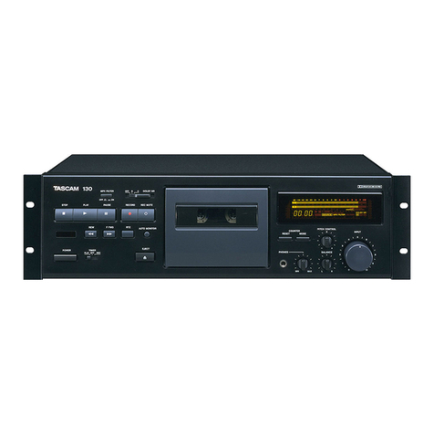
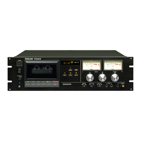
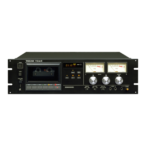
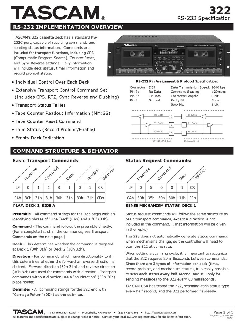
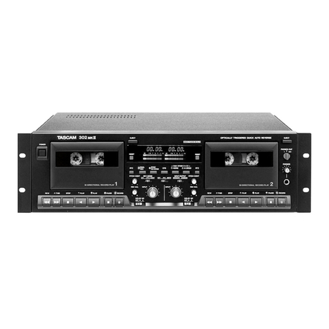
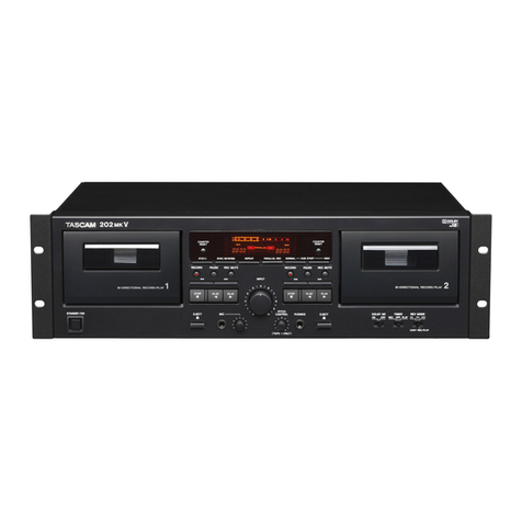
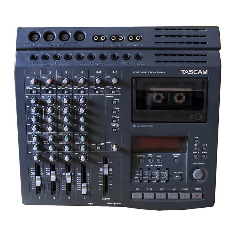
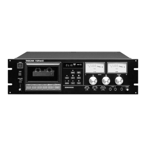
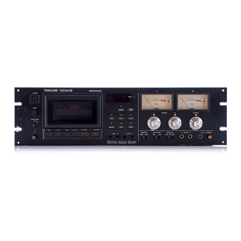
Tascam 122MKII User manual

•
TEAC
Pro
f
essional
Di
vi
sion
•
;
SERVICE
MANUAL
Master Cassette Deck
Effective:
March
,
1987
B
10124
5704035900

•
....
mn..l1
I
TABLE
OF
CONTENTS
, .
Specifications
.....
..........
....
....
..
........
·2
..
Block
Diagram
···················
·
···············3
2.
Removal
of
External
Components
. .
..........
·4
3.
Parts
Location
.....
.......
...........
.........
·5
4.
Test
Equipment/Material
and
Precautions
4
-1
Equipment
Required
for
Maintenance
...
·7
4-2
Precauti
ons
····
..
··
....
··
..
·
..
··········
·8
5.
Mechanical
Checks
and
Adjustments
5 - 1 Micro
Switch
................
.
..
.
......
11
5 - 2 Head Hight, Tilt
and
Azimuth
..
..........
11
5-3
Head
Base
Po
sition .
...........
.....
...
12
5 - 4 Pinch Roller
Pressure
..................
15
5-5
Reel
Torque
..........
......
...........
15
5-6
Tape
Speed
..........
......
....
..
......
16
......................
17
5 - 8
Cassette
Holder
5
-7
Wow
and
Flutter
........................
17
5-9
Damper
Adjustm
ent
18
5
-1
0
Voltage
Conversion
....
.......
......
" 18
6.
Electrical
Checks
and
Adjustments
6
-1
Playback
Performance
..
................
21
6-2
Monitor
Performance
...................
22
6 - 3
Recording
Performance
.
...........
. .
...
23
7.
Exploded
Views
and
Parts
Lists
......
. .
....
25
8.
PC
Boards
and
Parts
Lists
............
.
.....
34
9.
IC
Internal
Block
Diagrams
.
.......
.
....
·····44
Schematic's
.......
....
..........
,
...
....
......
Insert
1.
{±m:
....,... ............. ... ............ ..... ..
··2
70
';J? .
~l-1-v'f'5.b.
............
·
....
··
........
3
2.
9HH~~0)7l-
V/J
...
... .
....
.
.............
....
····4
3.
$~llCIT![18l
························
·
··
·
···········5
4. ;f.
/Tj-/A::E~~M·e~~H*
-
4-1.;f./Tj-/A::E~~t;f
........
·
..
·
..
·
....
· ·
..
·9
4-2.
;f.
/T-j-
/
A~t~l*
.......................
10
5.
ml~$OH·
I
';J
? e
ml~
5-1.-?.{?OA.{·;JT
···
···
·········
··
·
·······
11
5-2.
""Y
rO)~~
,
T'"
1-,
7:/71
A
.........
..
11
5-3.
"";J
P·"-";:-Alli.fi
.........
.......
.........
12
5-4.
C/T'
O-'5f:E¥:7J
..
..........
.........
15
5 - 5.
I)
-
'v'
I-
,"?
............................
15
5-6.
T-7~Jj'
....
.
........
.....
.....
.
.......
16
5
-7.
']?
.
'7
'5
'y
7
...........................
17
5-8.
:hi!.y
r .
*'"7'
5-9.
7'/I\~fl
18
.........................
17
5-1
o.
l(
EE~l~
................................
18
6.
~~iir¥l1J
/'1'$0)7
I ':J?
cml~
6-1
.
¥l~*
.............
.....
................
·21
6-2
.
=t=-7*
..........
...
.........
....
·.
....
··2
2
6-3.
~~iir*
..........
..
.... ...................
23
7.
)j-M[;2Jel'\-'Y'I)AI-
..
·
....
·
..
·
......
··
..
..
··25
8.
~l&l8lcl\-'Y'
I)
A
I-
.........
..
··
....
···
..
····34
9.
IC:l'o·;J?·$f-1-v'f'5.b.
....
·
..
·
........
·
..
·
..
·44
@]~il[;2J
...
.....................................
U:
{j'0.JJ

I
l~~
MK
ll
MECHANICAL
Tape:
Track Format:
Tape Speed:
Speed
Accuracy:
Pitch
Control:
Wow &
Flutter
1):
Fast Wind Time:
Motor:
Head Configuration:
Dimentions (W x H x D):
Weight
ELECTRICAL
Line
Input
(XLR)
Input
Impedance:
Nominal
Input
Level:
.
Minimum
Input
Level:
Line
Input
(1/4"
and RCA)
Input
Impedance:
Nominal
Input
Level:
Minimum
Input
Level:
Line
Output
(XLR)
Minimum
Load Impedance:
Output
Impedance:
Nominal
Output
Level:
Maximum
Output
Level:
Line
Output
(RCA)
Minimum
Load Impedance:
Output
Impedance:
Nominal
Output
Level:
Maximum
Output
Level:
Headphone
Output:
Bias Frequency
Equalization:
Recording Level:
Frequency Response2 ):
Total
Harmonic
Distortion
(THD)2)
:
Signal-to-Noise Ratio2 ) :
(Reference 3 %
THO)
Adjacent Channel Separation2):
Erasure2 ):
Power Requirements:
U.s
.
AJCANAOA:
EUROPE:
U.K
./
AUSTRALlA:
GENERAL
EXPORT:
Power
Consumption:
1. SPECIFICATIONS
1±~
Philips type
ca
ss
ette C-60 and C-90
4-track, 2-channel stereo
4.8 cm/s
(1-7/8"
ips)
±0
.5 %
±12 %
0.04 %
(NAB
weight_ed)
±0_08 % peak
(DIN
/IEC/
ANSI
weighted)
90
seconds
for
C-60
1
FG
servo
direct
-drive capstan
motor;
1 DC
reel
motor;
and
1 DC ancillary
3 heads; erase, playback and record
482 x 133 x 297
mm
(19"
x
5-1
/4"
x 11-11 /
16")
7.7 kg (16.94
Ibs)
net
40 k ohms, balanced
+4 dBm (1.23 V)
-4
dBm
(0.49 V)
30 k ohms, unbalanced
-10
dBV
(0.3 V)
-18dBV
(126
mV)
10k
ohms or more, balanced
100 ohms
+4
dBm
(1
.23 V)
+12
dBm
(3.1 V)
10 k ohms or more, unbalanced
100
ohm
s
-10
dBV
(0.3 V)
-2
dBV
(0.8 V)
100 mW/channel
maximum
at 8 ohms
100
kHz
3180
J.1s
+ 70
J.1S
(Metal,
Cr02)
318011s+ 120l1s (Normal)
160
nWb/m
(0
VU)
25 Hz -
20
kHz
±3 dB at
-20
VU
(Met
al
)
25
Hz -19
kHz
±3 dB
at
-20
VU
(Cr01)
25 Hz -
17
kHz
±3
dB
at
-20
VU
(Normal)
1 % at 0
VU,
400 Hz, 160
nWb/m
(Metal)
59dB
(NR
OUT,
WTD)
68 dB
(DOLBY"
-B NR
IN,
over 5 kHz)
78 dB
(DOLBY-C
NR
IN,
over 1
kHz)
Better
than
45
dB at 1
kHz
Better than 65 dB at 1 kHz reference
+10
VU
120 V AC,
60
Hz
220 V
AC,
50
Hz
240 V AC,
50
Hz
100/ 120/
220/240
V AC,
50
/60 Hz
24 W
- 1 -

1~~MI\J1
I
In
these
specifications,
0
dBV
is
referenced
to
1.0
Volt.
Actual
voltage
levels are
also
given
in
parenthesis.
To
calculate
the
0 dB =
0.775
Volt
reference
level (i.e., 0
dBm
in
a
600-ohm
circuit),
add
2.2
dB
to
the
listed dB value; i.e.,
-10
dB re: 1 V =
-7.8
dB re: 0 .
775
V. ;Ji
!;
v--<lvl;l.OdBV=IV, OdBm=O.775V
"C'U
<o
1tl.IIb ( )
L~l
LI'tTo
1)
Specifications
were
determined
using
TEAC
Test
Tape
OdBm=O.775V
~~
V--<lvC
OdS
= I
vp
v--<lvC
Ii
2.2dB
O)~/)'J;
MTT-111
':J
tTo
I) : '::O)ljO)(:tHlI;l.,
TA
f ·
T-7'TEAC
MTT-IIII~J:
,?
,,-j-o
2):
'::O)lJjO)(UlO)TA f .
T-7·1;I.
METAl
MTT-5571
2)
Specifications
were
determined
using
TEAC
Test
Tape
NORMAL
MTT-5511
METAL
MTT-5571
Cr02
MTT
-
5561
Cr02
MTT-5561
-cr
(:tIWLf9j.lill;t.~1§o)l:"'T~'~
<
~
T':''::
til
'.!;,? t T o
NORMAL
MTT-5511
-cr
f'
Iv
c-/
-1
X
'J
~.?
Y .
"Y
AT"
1;1.,
f'lv
t::--6}f~P.li/»"'O)
j[
~
III
;:lIIi;!i~~./1.L
\'
tTo
f'lvc-&Lf
ill
{;t.
,
f'lvt::·-6Jl~.Ii<o~l~i!lj"L'To
Changes
in
specifications
and
features
may
be
made
without
notice
or
obligation,
"Dolby
noise
reduction
manufactured
under
license
from
Dolby
Laboratories
Licensing
Corporation.
"DOLBY"
and
the
double-D
symbol
00
are
trademarks
of
Dolby
Laboratories
L'
icensing
Corporation,
..
-2-

122MKll
Block Diagram
REPRO
HEAD
..
C=I~~uj~
@
.'-<18,., IIAL
I
L-
___
_ _ _
__
_
~ J
~
~U
!
~
'f
A.
-
LOd
8"
~
@
"
"0
,;7
- IOd8v
OOL8Y
N. R.
I
D€COO£R
I
[~T~
P1d
!J
-I
O
dtv
---------
-
--
1
I
I
I
I
PEAK LED
vu
MEn:R
-,\':'
RE
C
1------,--
~
H
EAO
~
'
NORMAL
Cr02
METAL
-----
-~
~-----
--
_
\
_--
~
----
-----
-------
s c
f--
-HX
PRO
100
":1-0
R
01
L-
______________
________
__
~
f:.
ERASE
--
-
--
-
-U
x
HEAD
Ex
te
rnal Dimensions
,.
,",",
11
1 \ ,1
16"'\
19
m.-.
rJ/
..
··
1
'2)
l
P'ln1"o.lll
'
6
~
1
I
1.-1
.'-J
ttl
r@
~
~
~
-
~
~
y
..
-3-

l~~MKH
I
2
REM
OV
AL
OF
EXTERNAL
CO
M
PONENTS
~H~$~O)*
l15
Disassemble
in
number-order
~{}'lfjl:$'j-
L-""CT
~
L\ / .
.--
~/
,
,
I
.
,
,
,
, :
,Ql
.
e:
>
..
.
I
-
4-

12
2M
KII
3
PA
R
TS
LOCATION
$
J'tl
~c
f1i
rm
15
;
---14
---13
i----
12
---
. 8
:\'¥-
--1
0
SPEED TR IMMER
R5
02 6
16
7
11
1 REMOCON
PCB
ASSY 9 METER
PCB
ASSY
2
POWER
SW
PCB
ASS
Y 10 H. PHONE
PCB
ASSY
3
CONTROL
PCB
ASSY
11
MONITOR
SW
PCB
ASSY
4
B.
T
CONTROL
PCB
ASSY 12 REC AMP
PCB
ASSY
5 PITCH CON
PCB
ASSY 13
PLAY
AMP
PCB
ASSY
6 COUNTER
PCB
ASSY
14
MOTHER
PCB
ASSY
7 COUNTER
SW
PCB
ASSY 15
BAL.
AMP
PCB
ASSY
8 VR
PCB
ASSY 16
JOINT
PCB
ASSY, ADJ
SW
PCB
ASSY
Fig. 3 -'
Top
view
.lilD
~
-5-

Record
Safety
Switch
B.T
Sensor
Cassette-in
Switch
Sensor
Arm
PCB
Assy
Sensor
rm
./
Supply-------=:::;
Reel
Table
L
_.
__
~
j
..
",'J.
.....
_
I
J..::;Y
E
RASE
Head
Head
Ass'y
:;-..,....;+--------Ta
ke·u
p
Reel
Table
f-:----Pinch
Roller
Fig.
3-2
Cassette·i
n
Reel
Motor
Record
Safety
-----
Red
u
ctio
n
Pulley
Switch
--
-=---;
'--
:'..=.;=:o=
~
~.::..;;
;_..---
B.T
Co
ntraI
PCB
Assy
Damper.,----------~
~~
---------Cam
Mo
tor
1-
Fig.
3-3
"--
--
-6-

1
1~~MKJJ
4.
TEST EQUIPMENT/MATERIAL AND PRECAUTIONS
4-1.
EQUIPMENT
REQUIRED
FOR
MAINTENANCE
Equipment/Material
(Suggested
Type)
Used
for
Cleaner
TEAC
TZ-261A
(Head
Cleaner)
or
equivalent
Cleaning
heads
and
other
meal
components
in
tape
path
TEAC
TZ-261B
(Rubber
Cleaner)
Cleaning
pinch
collers
.-
Head
Demagnetizer
TEAC
E-3
or
equivalent Demagnetizing
heads
Screwdriver
Non
inductive (plastique,
wood)
Bias
tuning
Spring
Scale
0-
500 g
Pinch
roller
pressure measurement
Head
Alignment
Jig Jig
A,
TEAC
Part
No.
5736006600
Jig
B,
TEAC
Part
No
.
57
36006700
Head
height
checks
(longitudinal
and
horizontal)
Torque
Meter
Cassette
torque
meter
0-
100
g-cm
(Sony
model
TW2111
/2121)
0-160
g-
cm
(Sony
model
TW2231)
Reel
torque measurement
Wow/Flutter
Meter
General
use
type
Range:
0.
03
%
Sensitivity:
10
mV
or
more
_
..
Ava
i
lable
positions:
NAB,
D/N
/
CCIR;WTD/UNWTD
Wow
and
Flutter measurements
,
Frequency Counter
General
use
type
Sensitivity:
25
mV
or
more
Impedance: 1 M
ohms
or
more
Ra
nge:
1
Hz-1o
MHz
Tape
speed
measurement, Wow/flutter
measurement,
and
Bias
frequency
measurement
DC
Voltmeter
General
use
type
Digital
or
analog
Sensitivity:
0.1
V
or
more
DC
voltage
measurements
AC
Level
Meter
General
use
type
Level
range
: -80
dB
-
+40
dB
Impedance: 1 M
ohms
or
more,
less
than
25
pF
Frequency
range:
30
kHz
or
more
Signal
level
measurements
and
bias
adj
sutments
Oscillator
Available
frequencies :
10
Hz
- 1
MHz
Output
level:
3 V
or
more/6oo
ohms
(variable)
Distortion:
less
than
0_1
%
Test
signal
generation
Attenuator
General
use
type
Attenuation:
100
dB
or
more
Steps:
0.1
dB
Impedance:
600
ohms
Input
level
settings
Os
c
illoscope
General
use
type
(2
chan
n
el)
Sensitivity:
20
mV/DIV
or
more
Sweep
rate: 1
J,1sec
/
DIV
or
more
Head
azimuth adjustment
Distortion
Meter
General
use
type
Frequency :
400
Hz,
1
kHz
Sensitivity:
10
mV
or
more
Scale
ra
nge:
0.1%
or
wider
Output distortion check
Band-pass
Filter
General
use
type
Passing
band
width: 1 kHz(±lo %),
30
dB
or
more
/octave
Weighting
: IHF
Erasure
and
Crosstalk measurements
-7-

122
M
KB
I
Equ
i
pment/Matenal
(Suggested Type) Used for
Test Tapes
TEAC MTT-
l11
(Part No.
4900010100)
Tape speed and
..."ow/flutter
measurements
TEAC MTT-
150
(Part No.
4900011100)
(Dolby-B type) Output level adjustment
TEAC MTT-256 (Part
No.
490005090)
DIN reference
le
vel
Time constant
3180
+
120
~
sec
.
31.5Hz-14kHz
Head azimuth and Frequency response adjustment
Blank Tapes TEAC MTT-5511
(Pa
rt No.
4900041700
)
(NORMAl)
Test signal recordings
and
others
TEAC
MTT
-5561 (Part No.
4900041900)
(
Cr02
)
TEAC MTT-5571
(Pa
rt No.
49000
42000)
(M
ETAL)
Mirror Tape TEAC MTT-902 (Part No.
49000
15200)
Tape tra
ve
l check
4·2.
PRECAUTIONS
1.
Before
making
any
electrical
checks
and
adjustments,
be
sure
to
clean
and
demagnetize
each
head
and
tape path;
and
also
make
sure
that the tape
runs
smoothly.
2.
Repeat
checks
and
adjustments
for
Land
R channels
in
this order except otherwise specified.
Note:
Adjustment pot numbers indicated
as
ROO/ROO
refer
3.
to
channel L
and
channel R circuitries,
respectively
.
In
this
manual,
O.dBV
is
referenced
to
1.0
V.
-8-

I
"1~~
MK
JJ
.mt
M
(m::it6'o)
§
~1
7
')
-
-=-
/7
'
;i'9.
TEAC
TZ-26IA;?l/
("
'j
1-'7')-1-)
.HJ:U'f6J~
c
0"
,...""
''/
1".
7-7"
j-i -(
1"[§j0)
7
')
--=-
/7'
TEAC
TZ-261
B;i'9.
(7/\-
. 7
I)
-7)
.HJ:U'f6]
~c
00
t:'/7
o - 7
0)
7
')
-
-=-
/
7'
-...
../
I-'
-(1..-
-"1"
TEAC
E-3.H
J:
U'
iEJ
¥J
c
"c
-...
'/
~.
7-7
jf1
I-'O);ili!itl
r
71
/'
-
~~f,~'I1:
(7'
7;:Z
7
'/7
.
*~)
"-(7;:Z
7"'---=-/7
'
'ib'ff
0~500g
t:'/T
0-7
r±
. ip.l:it
-...
'/
I-'
~
C'
RJ!J~
ffl
;5~
;i:~
A
(
~¥
5736006600)
;i:i
~8
(
~o
~
5736006700)
-...
''/
1-'0);i)C'.
f:4:
IiUII~
~
)1.-7
;J
-7
jJ
-t
'/
~
~
)1.-7
;J-
7
O
~
IO
Og
-cm
(
'/
-=-
-
~
T
W2
111
,2
1
21
)
o~
160g-cm
('/
-=-
-~
TW2231)
I)
-)t.-
•
~
)t.- 7
'7'/
77
'/7
;J-
7
-If
~
ffl
1..-/::;
•
O,03%~
!'§ffl' I
OmV
t:J.
J:.
~Hf'I'
1
• JIS. NAB,
DI
N/
CCIR
WTD/UNWTO
'7'/
77
'/ 7 ;ftll:it
1~);IHll
.
;1)'//
7-
-1iI
~
ffl
~ffl'
25mVt:J.J:.
-1
/
t:'
-
7'
/
;:z
1 M 0 t:J.J:.
;~IJ
~
if-LEi;~
• 1
Hz
~
IOMHz
7-7
"
;:z
e' -
I-'
;~I
j
:it
'7'/
77
'/
7
;
~IJ:it
/,
-( 7
;:z
}t!~I~LEi
~~
;~
I
,
~
i~L
liL
1;
tt
!t
-JUffl
T::;
7
)1.-
;I'
t:
,;I:
?
TO
7'
i\
~~
• 0 1v t:J.J:.
lI
B:;lI
li
iE
AC
'
L--
'"'
)I.-~t
-
jij~
ffl
1..-/::;
-
80d8~
+ 40dB
-1
/
t:'
-
7'
/
;:z
1M
Qt:J.J:., 25pFt:J. T
J~");}1Z
;ii,*
j~
• 30kHzP.l.J:.
i~-l5-
I..-
'"'
)I.-;.~IJ~
/\1?;:Z
~Jl
>f
-
7'1
>f
}t1~~
I!
LiH~
• I
OHz~
I MHz
t±lhl..-,",)I.-
3 Vt:J..l:./ 600 Q
(Cf7£
)
U9'h$
.
0.I%t:J.T
J...h
fg-l5-
7'
'/7",-7
-ffl
::!
ffl
;Jit
RII: . 100dBt:J..l:. -
;:z
7
'/
7' •
O.
1
dB
-1
/
t:
' -
7'
/
;:z
• 600 Q
J...hiE-l5-
L--
'"'
)1.-~ltJE
>f
:/
o;:z::::r-7'
-~
9:
ffl
(
=fJt~
)
~~
20mV/DIV
t:J.J:.
a~ISi'fFe'
1
iJ.
sec/DIVt:J..l:.
-...
"/
r
?::;7;:z
~!l
u9'",.*~t
-~
~
ffl
J~L
Ei;~
• 400Hz, I
kHz
~~
10m
Vt:J.J:.
;~
IJJE
n
lID
•
0.1
%t:J..l:.
dj
h i=
~O)
U
9'''''
If'
;
~
IJ
~
-9-

122MKll I
I"
/
1"
• I "
:A
. 7
-{
)"
';1
-il
\i:
!fI
,,*J-'.'(
• I kHz
(±IO%)
30d8
tLI:.
/
OCT
"*~
•
~t.~tm.i::EIHnJl.ft,
;j!j
$,
~*
;
~I
J
;t
'7
D:A
I'
-
'7
JIJ
;t
0:'5-''T-7'
TEAC MTT-902 (49000 1
5200)
'T-7
'
~HT
'T:A
I'
'
'T
-7
' TEAC
MTT-II
I
(49
000 10100)
'T
-
7"i
~.oc,
'7'7'
7 '5
"/';1
!f1
TE
AC
MTT-
150
(49000
II
100) ;
Dolb
y
8-
Type
L--
"-
)"
ffl
TEAC
MTT-256
; DIN Ref. Level,
(4900
050900)
1l;'f;t~9.3180+
1
20/-L
se
c
31,5Hz~14kHz
"'
..
/
1"
),
::;7:A
,
mLIt
!j&
f;'j
'tt
!fl
TEAC
MTT-5511
(4900041700)
TEAC MTT-556 I (
4900041900
)
TEAC
MTT-55
71 (4900
042000)
7e '5
/7
'
'T
-
7"
(NOR
MAL)
7''5/7
'
'T-7
'
(CrO,
)
7 "
'5/7
'
'T-7'
(
METAL)
4-2
;J.
:";TT:";A~*{!:j:
1, 7
/1
f.~O)iJ;(j
f:to
)'i
.z
I;:.
,
i~~
A,
'/
~'
,
ii\1'fA,/
~,
T-
~
~ft
$*
~h¥h~~
0MmL,
1
0-+~~
m~
L~
T -
~
JtlT
jjl:f!.~H1U?c?'9
60
2,
'f1fU~:<EO)Jilt\'\llNIJ,
~
~&UT
.T.'/11;j,L
-
ch,
R-c
h o)
m
~f'f:~;'['"
~-y;
~
"o
t.!.lROO/ROO,
ROOO
/
ROOOo).J:.
?1
::'
~c~h~
,\
6@
~I\ifl:>'i
Ii
L - ch/ F -
ch
~.7J
;
L i
90
3,
OdBV
=
I,
OV
-
10-

head tilt adj,
(Refer
10
I 122MKll
5.
MECHANICAL CHECKS AND ADJUSTMENTS
~1.RB(J)T.I.
'/
-7
C
~~
5-1
MICRO
SWITCH
1.
Prepare a standard cassette
shell
with
the record protection tabs
in
place.
2.
Load
this cassette
and
close
the cassette holder.
3.
Adjust
mounting position
of
the two
micro
switches, cassette-in
switch
(S502)
and
record safety switch
(S501)
.
(for
switch
location, refer to
Fig.
3-3,
so
that the actuator position
is
in
the
setting
range
shown
by
Fig.
5-1.
4.
Be
sure
that the cassette-in switch
is
properly actuated to start
the
capstan motor.
5.
Make
sure that the record safety switch
is
properly actuated
so
that
when
depressing the
RECORD
button together
with
the
PLAY
button, the
deck
is
set
in
record
mode
(or
can
not
be
set
in
record
mode
if
the cassette loaded
has
no
tabs).
sensor
arm
-\!/-Ij--7-b
actuator
7'J;F"I-9-
=
micro
switch
71'JO:A1'y;F
7
fi
xe
d
screw
fID~:1<>
Fig. 5-1
5-2.
HEAD HEIGHT,
TILT
AND
AZIMUTH
1.
Set
head
check
jigs
A
and
B.
2,
Adjust height adjusting
screw
A
shown
in
Fig,
5-4
so
that
tip
of
non-marked side
of
the
jig
B
does
not touch the
guide
of
the
rec/PB
head,
but the
red
marked
side
touches the
guide.
3.
Apply
jig
Bto
head
and
check
for
tilt.
(Fig
.
5-3)
Adjust tilt adjusting
screw
B
(Fig.
5-4)
as
required. After
com-
pletion
of
the adjustment,
make
sure
the
head
height adjustment
is
not upset,
using
the step 2 above.
4.
Adjust
P/B
head
azimuth
by
adjusting
screw
C referring
to
item
6-1.
Adjust
rec
head
azimuth
by
turning adjusting
screw
0 slightly
referring
to
item
6-3.
After adjustment, repeat steps 2
and
3.
head
check
jig
B
(5736006700)
Fig.
5-2
-
11
-
setti
ng
range
t·y
T -I
/;f
iell!J
= \
P''''~'
O,5mm
adjusting
screw
""
IJ!lJH:)
5 - 1 7
-1
? 0 • A
-1
':J
=f-
l
.•
M*~~m~JM~~~~t~~~m.~60
2.
::...~~t''J
~~~-CIuL
,
~t'
'J
~.
;t;)v:7
-~
ML::60
3.
~
t
''J
H / . 7-.1
'd
'-
(S502),
~llIlJj~
7-.1
''J
f- (S501)
;It
(
jj!jj7-.1'
'Jf-
llJ(f1@lpJr'i12l3-3~~oo.L
71f-.:2
I
-:7
t'l.
~
t;'
~5-1
~t
''J
T 1 /
1'lliliiHli1'l!.:tJ
6
J:.
-)
1.:7-.1'
''J
f-
IIlH1t'l.iiiH~~~
6 0
4.
~
t
''J
~
1 / • A1
''J
f-IJ'
il
L <
friJllJ
L
-C
.f-
-V
7'
7-.
.y
/ •
-t--
:71J
(@]!\i[;~
61J
'
U1f.[r.~
6 0
5,
i1<~llJJ
J
tA1''Jf-IJ(iEL<fFijli)L-C,
REC
ORD10c
7'
l/1
fiD~-ml.:jffl~c,
U1f~I':~*iJ'-C~6.o,
('1t
~
(;l.~i~~
~JJJl:m
'J J
iJ'fil
'-C
l'
tJ
l'
~
t
''J
r
i;-g-C
Iv~~
.g-i':
Ii
iii
Wf-c~
tJl'i)')
O1fW~
60
5 - 2
"'"
':J
H7)
~
~,
=f-
Jt"
",
7:;
7 A
1.
A...
''J
F
'
~t'l.
Ii1
~~m
!"l,
A. B
~t
''J
~
~
6 0
2.
mAB~Mm~-C~B~A...~~~h1~~~~~~?-1
!lllj-ctf1
r:"':~6J:
-)
I.:12!J5-4
~A...';;
r"
;~~;f
,)
(A
)
-C
~~i!'it
~60
(
~5-2
)
3.
mAB~A...,;t
H':~-Cf-Jl.
·
rH[
~r,-
960
(~
5-3
)
i'1nI~'i*)
(B
)
cfft,i-)o
(~
5-4
)
~
~~j'TtJ"?
t.:.j&,
~
~
;b'H;btJ.o,"?
t~
7-.
T
''J
7'2
-cfJ'fLr.
''J
1~60
4 .
fJ'f~A...''J
F'~7)?A'i6-1~'':VE"?-c~
~
-i',)
(C)-C
1ltJ
-)
0
~ilA...''J
~'i6-3~I':VE"?-C~~*
:/
(D)
-CfftJ-)o
mJ~;f')
(0)
lili.o,tJ@)$l:;
(!
@)ij',z;)
-C
J: l
'0
mJ~H'TtJ"?~j&I;L
7-.T''J72~~~,
7-.T''J7·3~f-)[..
~
-2:-fJ'ff-:r.
";
1 L
-C
< t:"2':l
"0
head
check
jig
B
(5736006700)
Fig.
5 -3
scr
ew
Fig,
5-4
)
head
check
jig
A
(5736006600)

122MKll I
REG
Head
Azimuth
Screw 0
P/8
Head
j"Ij1:"." r
REG7:/7A!P.J~::j<:;
1350
180
0
(out
of
phase)
i$.tl.:f€l
P
/8
Head
----*<
Adj.
Screw
Tiit
8
Azimuth
Screw G
'---+-----'I--~
T)~
~ I!llU
*:;
P
/87:/7
A
Iil1
~
::j<:;
REG
Head Fig. 5-5
Ui>;l'''"-"
r
Fig. 5-4
5-3
HEAD
BASE
POSIT
ION
5 - 3 A..
'Y
1"
•
'"
-
:;z
{~
~
5-3·1
STOP
MODE
5 - 3 - 1
:;z
r
."
7' . 'I: -
r'
S;f
1.
With
the.
deck
in
STOP
mode,
adjust the
trim
pot
R547
(Fig.
,.
;Z
r
'J
7'·
-E-
r'
6;'f
I
::,
A..'J r' .
.r-(-;zt
h
,&
LT:1JI
::
< 0
5·3)
so
that the
head
base
comes
to
the
lowest
position.
J:.-51:::f-~;:EtlUJ'i:R547
(~5-6)
~
~~-
r
00
2.
Turn
the
reduction pulley
(see
Fig.
3-3)
with your
hand
to check
2.
i.!'!i.:i!E7'-
I)
(
~
3-3
$
@.)
-'2:-.f--C@]ti6-t±",
A..:;
r·.r-(-
whether the
head
base
exceeds the
lowest
position adjusted
above
or
not.
;Zb
(
J::.~2(.T)iJ3J
~
ilL
iil
J:.1J
~
GI::T"-
<
0b'c.
-5b
'
li
rW
!'-r
00
3.
If
it
does,
adjust R
547
again
.
3.
:blT"-<0J:.-5
tj.Gl;t:,
R547-'2:-2'GI::
~
~
9"
00
4.
Repeat
steps'
through 3 until a
good
result
is
achieved.
4.
1~3J1iH:i:IJ~l""[,
*j!j~!Udl!
.<
tj.0J:."3I::9"io
5.
Operate
the
deck
in
the sequence
of
PLAY,
STOP,
PLAY,
and
5. f v
-{
.
-E
-
r'
1.1
'
G;z
r 'J
7"
'I:
-
r,
i-
L
""[
f v
-(
.
-E-
finally power-off modes. Repeat this sequence
two
or
three
r'b'
G
'iUitll
-'2:-1:;J]0HtfF-'2:-
2,3
OC
~
IJ
iZ9"
0
times.
6.
5XjjH~7i&,
A..
:;
r'·
.r-(-;Z(.T)
~
llilL
!iti
-'2:-~
00
b
L,
3
6.
Then
observe
the stop position
of
the
head
base.
If
the
head
J1i-c~'fIi2:
nt:
itz.iU
J:.
I) TI.: <0
J:.
-j
ti
G
1;1'-
R547
-'2:-
2:
G
base
still
exceeds than the position
in
step
3,
readjust
R547
and
repeat steps 1 through 5 until the
head
base
comes
to
the lowest
1::
~,,~
L6;:I::l
~5J1iH
~'JiZl""[,
A..
..
; r'
·.r-(-
;Z
/)'UiL
position. T I:: <0
J:.
-j
I::
9"
00
5·3
-2 F.F./REW
MO
DES
5-3
-2
F.F
./
RWD'I:-
ra~
1.
Run
the
deck
in
the F.F.
(fast
forward)
or
REW
(rewind) mode 1.
F.F
(
!f!iiS
'J)
~
U;I:
RWD
(!f!
~~
U
-E-
r'
CPI
::
n
(.T)
and
adjust the trim pot R544
(Fig.
5-6)
so
that the following
tJ\~tJ{1~
Gn
0
J:.
-5
1::
~
~
IlIl~t1
UI[
R544
(egj
5 -
6)
-'2:-mJ~9
two
conditions
are
obtained. {)o
a)
A clearance between brake drum
and
brake
pad
("A"
in
Fig
. '
J"v-;j:-
·
r·'5Lc
7v
-;j:-·/
{,/
I~O)9"~
n
JJ
(~5
-
7
0)
5-7)
of
approx.
1.5
to
2
mm
.
b)
Head
base
should not
go
too
far
up
(so
the
heads
do
not A )
b{*~
1.5mm~
2mm
-cas
0
~
Co
touch the
moving
tape,
and
quick braking action
is
possible). A..:I
r'·.r-(-
A
i;l:""[
g;
0
t::ij"
J::.:1J
A..
rrb,tj.l'
~
C
....
tE
il'
2.
Repeat
switching operations
from
the
STOP
mode
to
F.
F.
or
go(.T)T-7'b<~A..J
r·'::~Gtj.l,
tl(
t
§
-'2:-i!}
~
p"
7:;J:.U7
R
EW
mode
two
or
three times
and
make
sure
the
above
adjust- l/-;j:-(.T);7
-{
~
/ j'-'2:-c
g;
o
t::
ij"Ef. <
9"
~?'~o
ment
is
satisfied. 2,
;Z
r
'J
7'
. 'I: -r'tJ' GF,F
..
~
t:
1;1:
RWD
'1:-
r·",,-(.T)
i;7]~
;{,
~fF-'2:-
2,
3
1jt
~1J
~LJ
::f,
2(.T)ifnlTl-'2:-f,li1jg
L
n'0
N
"fW
:'9
00
-
1?,-

I 12
2MKD
R537
R546
R547
TAKE-UP
CUE
R544
R545
FAST
F. PAUSE
Fig. 5-6
-13
-
5-3-3
PAUSE
MODE
1.
With
the
deck
in
the
play
mode,
check
that there
is
clearance
of
0.5
mm
or
more
between the
pinch
roller
arm
and
the
spring
arm
("0"
in
Fig
.
5-8J.
2.
Set
the
deck
to
PAUSE
mode
and
observe
the clearance between
the
pinch
roller
and
capstan shaft
("8"
in
Fig.
5-]).
It
should
be
0.5
mm
or
more.
3. If not, adjust the trim pot R545.
4.
Repeat
switching operations from
STOP
to
PAUSE
mode
two
or
three times,
and
make
sure
that
when
repeating steps 1
and
2,
the clearances
"0"
and
"8"
are
within the specified
range
respectively.
Also
make
sure there
is
a clearance between
head
base
and
spring
stud
("e"
in
Fig.
5·B).
5-
3-4
CUE
MODE
1.
Load
a prerecorded tape.
Make
sure
cue
signal
is
developed
when
the
FF
or
R
EW
button
is
pushed
with the
PAUSE
mode
set.
If
the
cue
signal
is
not
devel-
oped
or
the
level
is
excessively
low,
adjust the
trim
pot R
546
(Fig.
5·6).
5-3-3
;f,-;;(.
'1:-
f:"i!\'f
1.
-.1
v
l'
.
'C-
n:
L
l,
t'
'./
T • 0 -
'7
. 7 - L c
:A
7'
I)
'./1/"
7-L0)9~F"jJ
(~5-80)D)
;I)'~;10.5mm0...tlJ:,
7.>;I)
'
E1li~r.9
.00
2.
;f-;Z"'E--r'0)1fIH:t''./T"O-'7c4-t
' 7':A:$''./ "
'./
,.7
rO)r,,91lAA
(~5-70)B)
;I)'1f.10.5mm0l:.-CJ:,7.>;I)'Mm~
97.>0
3.
bL?'j.nn\.o~i5"I;l:,
*[?Dfi'tllmR545c~1-t9Qo
4.
:A
r':J
7'"
'C-
r';I)'
G;f-;z"
'E--
r·-'"'.O)!;JJW!;ttilfFi-
2,
3~~IJ~U.:1!Z,
fl)jtl,
2
J.]jO)T~·:J
:7i-Ll,
r
.f1~
Dc
B;I)'i-ni"nmfi'iilllJ;I),f,«m9.oo
"£
t.:,
-'"'.
-;;
l-'" r;: -
:A
c
:A
7'
I)
'./ 7'5(ttc
O)Fs']
(~5
- 80) C)
~:
9"
i)dk91i'j) Q
;I)'li'(i
W9Q
o
5-3-4
=f-.::>.-' 'E--
F'
1.
Uf§-~7j.O)T
-
7'i-IrliA
9
Qo
;f
-
7.'
"
'E-
-r'1: Ll
F'
F'
;f
yo
'./"1
t.:
1;;1:
REW;f.
yo
'./
i-
jIjI
L
t.:MiI:
=f-.:L
-
~~1i'
tJj
Q;I)'
c'
-)
M«t
~.
r
,
9
7.>
0
4-.:L
-
~-l'j
1i'
tJj
t
H\;I),;l:
t.:!;l:
{g
~
v
r;:
)t-.tJ'~H
I
MI:{rl;~'l.f!;
~
(;l:
,
¥[i!!JJ.E
m
ttR546
(f;6J5-6)
i-iJ.'iJ1
~9
Qo

122
MK
H
A:
(approx.
1.5
~
2mm)
during
F-F
or
REW
A :
O~
1.S-2m
m)
F.F.xl<t
REW
'E-
1"
1J;'j
H
ea
d
base
should be in the
lowest
posit
ion
during
STOP
mode
~7~
'
~
-
~
~~~77,t-~
IJ;'j~~tT~~<~~~
Fig. 5-7
c:
during
PAUSE
mode
Pinch roller arm
t' /
7-0-57-i.
C:
;i(-A
' ,
t-
H<¥
Pinch
roller
spring
-~
7')
/'1
Fig. 5-9
t'/7-0-5
Fig.
5-8
Spring arm
~7'.J
/'f7
-.L..
-14
-

right reel
table
tab
®
7'1
I
122
MK
JJ
torque
adjusting ring
~
Jv?
!P-Jyl)
'./";/
Fig. 5-10
51
~
I)
-Jv7'-7Jv
-15
-
5-4
PINCH
ROLLER
PRESSURE
1.
Pushing
up
the cassette-in sensor
arm
(refer to
Fig.
3-2),
activate
the
play
mode.
Keep
the sensor
arm
pushed
up
during
measure-
ment.
Note: 0
uring
play
operation,
make
sure
there
is
a clearance
of
0.5
mm
or
more
between
the
pinch
roller
arm
and
the
spring
arm.
Refer
to
Fig.
5-8.
2.
Hook
a
spring
scale
to
the
small
opening
on
the
pinch
roller
arm.
3.
Pull
the
scale
as
shown
by
arrow until
the
pinch roller
moves
away
from
the capstan shaft
by
approx. 2
mm,
and
then allow
the
pinch
roller
to
just touch
the
capstan shaft
again
.
4.
Read
the
scale
when the pinch roller just starts
to
rotate.
The
reading should
be
from
350 g to 500 g
(12.3
Oz.
to
17.6
Oz.l.
5.
If
the pinch roller
spring
(Fig.
5-9)
was
replaced
for
repair,
always position the spring around
the
lower
half of the spring
shaft
as
shown
in
Fig.
5-9.
5-5
REEl
TORQUE
5-5-1
TAKE-UP/BACK
TENSION
TORQUES
1.
Load
a cassette torque meter
in
the cassette holder,
and
run
the
deck
in
play
mode_
The
meter reading should
be:
Take-up torque (right
reel
table):
47
to
53
g·cm
(0.65
to
0.
74
oz·inch)
Back
tension torque
{left
reel
table}: 9
to
11
g-cm
(0
.
13
to
0.15
oz-inch)
2.
If
the
back
tension torque
is
out of limits, adjust
the
trim pot
R116
(Fig.
5·6).
The
adjustment should
be
made
about
15
sec.
after
the
reel
starts rotation.
Read
the torque meter
for
about 5
sec.
after
completion of the adjustment.
3.
If
the
take·up torque
is
out of the limits, adjust
the
trim
pot
R537 (refer
to
Fig
. 5-6).
4.
If
the take-up torque
is
still out
of
the limits, adjust the torque
adjusting
ring
provided
on
the right
reel
table.
The
torque
can
be
adjusted
to
three
values
as
shown
in
Fig.
5-10. Turn
the
torque adjusting
ring
with the
tab
® ' pulling slightly upward,
and
place
the
tab
on
one
of
three stepped portions
having
pawls
to
fix
the
tab
.
5.
Repeat steps 2
and
3 until good results
are
achieved.
Caution:
In
each
trac
k measurement, a cassette type torque
meter
is
used.
The
torque meter should
be
calibrated
with a reference
dial
type torque meter.
5-4
c:/:r'
D-5ff7llr:7J
1. tJ-t!"1
r1/·-t!/-+J--·7-1.,.
(~3-2~!RO
~1::;!)'':
jfp
V(,
7v1
.
'C-
I"I.:g-;;,o ill'j:iE$,
-t!
/-+J-- •
7-
1.,.
li1::;!)I.:J!II Lf.;W;;,
:.
c!::
0
ff!(:
7v1'
'C-
""$,
to/7'
0-5'
7-1.,.c!::7../')
/
'i'
• 7 -
L.Fa9'=¥J
O.5mm
01:0)g-
~
ItfliJ<j);;'
1-l'li
'Gir.i2
,g- {,
(~5-8~ffll)0
2.
to/7'
0-5'
7-1.,.O)/J\~l\1\'':/'*~~/!Ht;;,o
-
3.
C:'-7'
0-5iJ<4--I"/7..:9
/.
~-I"
7
riJ
'
G*"J2mm~~h
;;',,1:
-)
'.:ff~9<:EI]O):;!)iDJI.:~I~-:,f:l~L
t°:'-7'
D-5/)<
~lf4--I"
77..:9
/.
~
-I"
7
I'
I.:tfiMg-;;,,,I:?
1.:11#<1:[
I.:~g-o
4.
t·:,-
7'
0
-5
/)<@I1)
Ii
ll6
{,
MjO){jj[
HJi:t.'o
iJl'j~tu)i(;l:350
-500gO)~ItIlA'':}..;;':'
C!::O
5.
{,L~E!!.O)t,:I6'.:t·:'-7·0-5';A/')
:'-'i'
(~5-9)
0)
XW!~
L
t:I~Hi,
£'9~5-
9
0),,1:
?
I.:
7..
7'
I)
:,-
'i'
~
7..
7°
I)
:,-
'i
' •
~
-I"
7
I'
0)
TOlin.:
{iLtili
~
-t±-
;;,
0
5-5
I)-lv'
r-lv?
5-5-17-1'.77
·;/
/'
1')"'.7//\,;/'.7.
7-/:/3
/.
1')"'.7
1.
fJ
-t!
'J
I'
•
T-)":$"
-I':
tJ
-t!
';J
I'
•
1')[,,
:1
• } -
:9
~~
C
A.
j&,
7'v1
''C-
"'I.:g-{,o
.!.l'l:rEi~'if1::O).ir1il)cg-o
T 1
'i
7
':J
7'·
1')["
'i
(;fi
I)
-)["-Ei): 47- 53 .
em
I'
';I
'i
• T /
~
3
/.
1')["
'i
(;t
I)
-
)["-Ei)
:
9~
II
.
em
2.
I'
':J
'i
T /
~
3
:,-.
1')["
'i
/){t~:iE
figiJ' G
7i-h
c l \{,
~A
Ii
*~:iEHlI1i:RlI6
(J;ZJ5-6)
~
ml
~g-{,o
f,
;
Il!1t
li7..:$'-
H
t"J15fY
t:?-C/)'Gm.J1~g-~0
it:,
:CO)i
i
O):l*li~
m 5
f»)
-n«n,ll,
g-
~
0
3,
{,LT177':J7··
t-)[,,:I/)~mfE{@/)'G7i-t1.-C~\{,~i~"i,
*~
AEHll1i:R537
(
12?J5-6~fffi
)
~~~g-{,o
4,
{,
LT-1:17
':J
7'·
t-)[,,
'i/)~
~'.:m:rEiU'G7i-h-Cl\{,:l£l
~I;t,
:5
')-)["-Ei'0)
r)[,,'i
mJ~
l)
/'i'H§JLc
~~
-g
{,o
I'
)[,,'i
li~5-101.:~g-"I:?
1;::3%i:~I.:mJ~cili
{,O
I)
-)["
-Ei0)?-tJO)j);;,glb1t'::
'
IH.li:lliHI~5H.:
':J}
iJ~~lt
Gt1.-C~\
{,OYc\
~~
M{I':'i:97·A~f1f-t;,1:'f~"I:?I.:Lc
r)[,,'i
~~~
I)
:,-
'i'
~@Ig-
0
5.
2,
3JfjH~I)~Lci
li
:i@
t-)[,,
'i
~*I6{,o
;.i,
~:
:c
h-'C~1.O)
I'
-7
';/
'i
Ii
tJ
-t!
')
I'
:$'
1
/0)
1')["
'i
} -
:$'
-TiM:rEg-
{, 0
iJl'jAEg-
{,
ilIl
I':,
t~~:$"
1 7 )["lliI r
)["
'i}
-:$'
-T~lE
L
-C.:lO
<a

122MKD I
5-5-2
F,F.lREW
TORQUES
1.
Load
a cassette torque meter
in
the
cassette holder
and
measure
starting torque
for
both F.F. (fast forward)
and
REW
(rewind)
operations with the tape wound
close
to
end
or
rewound
close
to
beginning,
respectively.
The
reading
should
be:
F.F
. torque (right
reel
table):
more
than
55
g-cm
(more
than
0.76
oz·inch)
R
EW
torque
Oeft
reel
table):
more
than
80
g,cm
(more
than
1.1
oz-inch)
5-8
TAPE
SPEED
1.
Connect a frequency counter
to
either
one
of
OUTPUT
jacks.
Fig.
5-11.
2.
Depress
POWER
switch
to
ON.
3,
Load
a
TEAC
MTT
·
lll
test tape containing a 3,000
Hz
test tone,
then
leave
the
deck
for
at
least
one
minute
to
warm
up
the
capstan motor.
4.
Playback
the test tape,
and
make
sure
the
following
values
are
obtained
at
the
beginning
and
at
the
end
of
the
tape.
(PITCH
CONT
SW:
OFF)
Deviation.:
3,000
Hz±30
Hz
PITCH
CONTrol
range
:
More
than
±12%
for
the
speed
when
(PITCH
CO
NT
SW:
aN)
PITCH
caNT
is
set
to
off.
5.
If
the
speed
is
out
of
the limits, adjust
as
follows:
a)
Clean
the tape path and check the
pinch
roller pressure
and
take·up torque.
b)
If
they
are
normal,
push
PITCH
CONTrol
(off),
and
repro-
duce
approx. the
mid
portion
of
the
test
tape_
c)
Adjust
the speed trim pot
R502
(refer
to
Fig.
3·1)
provided
on
the
rear
side
of
the
PITCH
CONTrol
switch
using
a
small
"-"
driver
with
the
handle
completely insulated
from
the
blade
to obtain a
3,DOO
Hz
±5
Hz
reading
on
the
frequency
counter.
oscillator
0
~~
0
attenuator
Lt~~~o
LINE
IN
Fig, 5-"
-
16-
5-5-2
F.F
/
RED
I--JV?
1.
h1::';1
1--'
;i;)[,,;)1,=h1::
';1
1--.1--)[,,:7.
J.
-;)1'2:-li<-Clvl,
F.F.C!'f!i!IJ)
illIJfF
O)
~mJJ
r)["
:7
'2:-7-7
'0)~rtlJilI<-C,
~
t:..
RWD
milftO)jfj;ruJJ
r
)[,,:7
'2:-T
-
7'O);IJ;!tIJ~ili
< c
t-
h
i"hi!l'J!:E9~0
m~'ii;,:
O)
iIDl)c9
0
f
.f
. r)[":7
(;t]
I)
-
)["-EJ
) :
55g'
em
0...t
RWD
r)
[":7
(b:: I) -)["-EJ)
:'
BOg
· em
P)...t
5-6
T--:i~~
1.
mJi1ii:~h
'/
/;)1
'2:-
OUTPUT:';
t,
';1
:7
'=~*'t9
6
(~5
-11
ts:~)
2. POWER A'"
';1
T'2:-¥P
l-C
:;t /
'=96
0
3.
.f-
t"
7'
A;)1 / • t -
;)1
'2:-@J$j;~
i:t
'/
,t -
~
/
:7'7
'
;1
'19
~
t:..
66
1=
TEAC
MTT
-
III
T A
I--
• T -
'1'2:-li<-C
Iv
l-C,
Y
< C b-7tFEIl-'t
0)
~
~
1=
l-C
to
<0
4.
TAI--'T-'1'2:-~~~i:t,
T-'1O);IJ;!tIJ~c.rtlJ~-C
'f
ii
2
0)
@:;I)q~
Gh
~
;I)
'
~1fill9
00
{ijj~:
3,OOOHz± 30
Hz
PITCH CONT A
'"
';1
T
OFF
t"
;1
T .
:::1
/ r 0
-)
[,.
Q}~~lID
CP
lT
CH
CON T
A'"
';I T
ON) :
PITCH
CON
T :;t 7
MjO)iill!Jt'=j:'i
l-C
±
12%
0J:.
5. b lilEfi:
;I)
<flj[ffi;l)
'
Gnh
-Cl,
\
6
JJil
~I;t
,
i;,:O)
iilllJ
fJ
W
l
\
~
9
~o
a.
T-'1~ft~'2:-~~l-C,
~'/T,o-5ff
.~
,T'"
:7
7 'J
'1'
r
)[":7
'2:-
T
J.
;I
:7
960
h.
-'to)t5~;I)<iI*,-C;})hI:C
~'
;lT'
:::1
'/
l--o-)[,.~:;t7
i
=~i:t
,
77..
I--
•
7-'10)7-'1~~0)r:j:liJc:~jff
~
9
60
C,
mJitl~h
'/
/;)1
;I)<3,OOOHz±
5Hz~
jf;9
J:.
-)
1=
t'
'
;I
T •
::J
'/ r 0 - )
[,.
•
A'"
'
;1
T
O)
~ffilli
:.
J)
6 A
t'
-F
-'¥~:lEIJlm
R502
(12{)3-1~ml.)
H~Jl-C~~960
~f!f':.(iWW]]
*;1)'
G5Ci:I:'~~~
h
-C
l,
\
6IJ\~<'"
-j- A . r
5..,
I
'~
,Elj
l,\o'::'c
o
frequency
counter
I
~oJ
DECK
under
test
wow/flutter
m
eter
ETI
OUTPUT
0 0

I l :"::":MKH
5-7
WOW
AND
FLUTIER
5-7
'J9'
77':;9
~.
:
~-~
~
~~~.~M.~
ft~
~~h~h~~
L
£~o
Note:
These
measurements should
be
made
at the beginning,
middle
and
the
end
of
the tape.
1.
Connect a
wow
and
flutter meter
to
the
deck
as
shown
in
Fig.
5-11.
2.
Load
and
playa
TEAC
MD
-
ll1
test tape
or
equivalent.
3.
Measure
the
wow
and
flutter
value
.
Specifications:
±fl
.
08%
peak
(0I
Nil
ECI
ANSI
weighted)
0.06%
(NAB
weighted)
5-8
CASSETIE
HOLDER
1.
Adjust
the holder
guide
plate's mounting position
so
that
when
the
cassette holder
in
which
the cassette
tape
is
inserted
is
closed,
the
parallel
condition
shown
in
Fig
.
5-12
is
obtained.
Viewed
from
right
side
:tJ
GlI
J
iID
iEl
-0
0
2.
TEA
C
M
TT-111
~
7
~·~-~;!:t:!itEl~.iH·~-CA..,
L
-Cif}~~
-0.
3. '7
'.7
• 7
-7
./
7 ~
~i1lIJ:tE~-O.
1:
]1111:
O.06
%
WRM
S
(IVM
&
llfiiD
5-8
jJ~.:;
I'-
•
;f\Jv9
"
1.
tJ
t
'/
~
tJ\
~
?
J....
2:
h t
::.
tJ
t '/
~
-
;t)
v7'
~
rNl
L
-C
.
~
5 -
12
!::~"t
S¥
ntk
~7J<1.lfi.
Gh
-0
J:.
? t::;t)v)f.
jj
l'
1,"
1.&
0)
ffi(fitL
1iR
~M\I~"t
Q o
cassette holder
1Jt
·y
~*
'
I-
$"
-
holder
gu
ide pIate
* '
I-$>"
1H
r~
holder guide plate adjusting screw
*,
I-
$"
• :tf
-i
rt&IJl1!!;j<
:J
Adjust
unit
parallel can be got.
'¥
1
jl:
>;':
QJ:.
-5
!JlJM
Fig.
5-12
-
17-

l;':~MKn
5-9
DAMPE
R
ADJUSTMENT
5-9
$"//\'mJR
1.
Load
a
C-60
tape
and
close
the cassette holder
(with
the door 1.
/7
'./'J
·j--
7 (
MTT-5511)
~~-CA,L"C
h
t'
j r·
cover
attac
hed).
*)(.,:$"
(f7
{q-)
HI!
L.Qo
2.
Turn
the
air
adjusting
screw
so
that
when
pushing
the
EJECT
2.
EJE
CH
D~W
Lt:::II;'f, h t
'j
r .*
)(.,;Y"tJ
i O.5
fY-1.5f
YO)
button, the cassette holder
opens
smoothly
and
completely,
~rJl-ctJ66
GtJ,t:.tJ'-::Ji
Gi:t:.fffi
<
d:
j
i:.,
.:r:.
7imlJi!;f.)~
taking
0.5
to
1.5 seconds.
@]L-C~!l-t.Q
o
air
adjusting
screw
8mm
Damper
IIllfrl!,!ill
Fig.
5-13
5-10
V
OLTAGE
C
ON
VE
RS
I
ON
(FOR
GENERAL
EXPORTMODELS)
ALWAYS
DISCONNECT
THE
POWER
LINE
CORD
BEFORE
MAKING
THESE
CHANGES.
1.
Locate
the
voltage
selector
on
the
rear
panel.
2.
Using
a
regular
(slot
blade)
screwdriver, turn the selector
until
the
numerals
corresponding the
voltage
requirements
of
your
area
appear.
3.
We
suggest
you
label
the
rear
panel
with
the set
AC
line
voltage.
Note
:
Select
50
Hz
or
60
Hz
by
S501
on
Control
PCB
Ass
'
y.
Fig. 5-14
[;1:]
50Hz/60H
zO)
tTJ~I;I.::J
'./ r
D-)("PC
B
ASS·y..to)A
l'
'j
f-
S501
-CfTtJ~\i-to
-
18-
Table of contents
Other Tascam Cassette Player manuals

Tascam
Tascam 202mkV User manual

Tascam
Tascam 112mkII User manual
Tascam
Tascam 202 MK III User manual

Tascam
Tascam 102MKII Guide

Tascam
Tascam 202mkV User manual

Tascam
Tascam 302 User manual

Tascam
Tascam 688 Midistudio User manual

Tascam
Tascam 112mkII User manual

Tascam
Tascam 122 User manual

Tascam
Tascam 202mkIV User manual

Tascam
Tascam 202mkIII User manual

Tascam
Tascam 112mkII User manual

Tascam
Tascam 302mkII User manual

Tascam
Tascam CC-222 User manual

Tascam
Tascam 202mkIII Guide

Tascam
Tascam 122MKIII User manual

Tascam
Tascam 122MKIII User manual

Tascam
Tascam 302 User manual

Tascam
Tascam 122 mk III User manual

Tascam
Tascam 122MKmIII User manual