manuals.online logo
Brands
  1. Home
  2. •
  3. Brands
  4. •
  5. Tascam
  6. •
  7. Cassette Player
  8. •
  9. Tascam 122MKIII User manual

Tascam 122MKIII User manual

Other manuals for 122MKIII

3

This manual suits for next models

2

Other Tascam Cassette Player manuals

Tascam 112mkII User manual

Tascam

Tascam 112mkII User manual

Tascam PortaStudio 424 User manual

Tascam

Tascam PortaStudio 424 User manual

Tascam 112mkII User manual

Tascam

Tascam 112mkII User manual

Tascam 202mkIII User manual

Tascam

Tascam 202mkIII User manual

Tascam 202 MK III User manual

Tascam

Tascam 202 MK III User manual

Tascam 112RMKII Guide

Tascam

Tascam 112RMKII Guide

Tascam 202mkIV User manual

Tascam

Tascam 202mkIV User manual

Tascam 122MKIII Guide

Tascam

Tascam 122MKIII Guide

Tascam 302mkII Guide

Tascam

Tascam 302mkII Guide

Tascam D00935220B User manual

Tascam

Tascam D00935220B User manual

Tascam 122MKmIII User manual

Tascam

Tascam 122MKmIII User manual

Tascam 202MKVI User manual

Tascam

Tascam 202MKVI User manual

Tascam 130 User manual

Tascam

Tascam 130 User manual

Tascam PortaStudio 424 MKII User manual

Tascam

Tascam PortaStudio 424 MKII User manual

Tascam 122MKIII User manual

Tascam

Tascam 122MKIII User manual

Tascam 302 User manual

Tascam

Tascam 302 User manual

Tascam 102MKII Guide

Tascam

Tascam 102MKII Guide

Tascam 122MKII User manual

Tascam

Tascam 122MKII User manual

Tascam 302mkII User manual

Tascam

Tascam 302mkII User manual

Tascam 202mkV User manual

Tascam

Tascam 202mkV User manual

Tascam 122MKIII User manual

Tascam

Tascam 122MKIII User manual

Tascam 688 Midistudio User manual

Tascam

Tascam 688 Midistudio User manual

Tascam 202mkIII Guide

Tascam

Tascam 202mkIII Guide

Tascam 102MKII User manual

Tascam

Tascam 102MKII User manual

Popular Cassette Player manuals by other brands

Ahuja CPA-360 Operation manual

Ahuja

Ahuja CPA-360 Operation manual

Sony Pressman TCS-60DV Specifications

Sony

Sony Pressman TCS-60DV Specifications

Philips AQ6485/14 Product information

Philips

Philips AQ6485/14 Product information

Sony TCM-200DV - Cassette Recorder operating instructions

Sony

Sony TCM-200DV - Cassette Recorder operating instructions

Nakamichi BX-300 Service manual

Nakamichi

Nakamichi BX-300 Service manual

Panasonic RQ-E25V operating instructions

Panasonic

Panasonic RQ-E25V operating instructions

Aiwa TP-VS535 operating instructions

Aiwa

Aiwa TP-VS535 operating instructions

Yamaha MT8X Operation manual

Yamaha

Yamaha MT8X Operation manual

Sherwood Newcastle D-480 operating instructions

Sherwood

Sherwood Newcastle D-480 operating instructions

Manta MA408 user manual

Manta

Manta MA408 user manual

GPO W0162B user guide

GPO

GPO W0162B user guide

Marantz CP230 Service manual

Marantz

Marantz CP230 Service manual

Sony HST-471 Service manual

Sony

Sony HST-471 Service manual

Sharp JC-AV1 Operation manual

Sharp

Sharp JC-AV1 Operation manual

Pioneer CT-W103 Service manual

Pioneer

Pioneer CT-W103 Service manual

Sony CFS-B15 - Am/fm Stereo Cassette Recorder operating instructions

Sony

Sony CFS-B15 - Am/fm Stereo Cassette Recorder operating instructions

Sony WMFS220 - Portable Sports AM/FM Cassette... operating instructions

Sony

Sony WMFS220 - Portable Sports AM/FM Cassette... operating instructions

Aiwa HS-TA21 operating instructions

Aiwa

Aiwa HS-TA21 operating instructions

manuals.online logo
manuals.online logoBrands
  • About & Mission
  • Contact us
  • Privacy Policy
  • Terms and Conditions

Copyright 2025 Manuals.Online. All Rights Reserved.

www.SteamPoweredRadio.Com
TASCAM
TEAC
Professional Division
122MK1ll/
112RMKll/112MKII
Stereo Cassette Deck
(
___
O_W_N_E_R_'S_M_A_N_U_A_L
__
) 5700140701
www.SteamPoweredRadio.Com
2
THE APPLIANCE CONFORMS WITH
EEC
DI
REC-
TIVE
87/308/EEC REGARDING INTERFERENCE
SUPPRESSION
CONFORME
AL
D.M. 13 APRI LE 1989
DI
RETTIVA
CEE/87/308
Bescheinigung des Herstellers/lmporteurs
Hiermit wird
besche
i
nigt
, daB
der
/die/
das
Stereo Kassetten-Rekorder 122 MKlll/112R MKll/112 MKII
(GerAt,
Typ
,
Bezeichnung)
in Obereinstimmung mit den Bestimmungen
der
AMTSBLATT
163/1984,
VFG
1045/1984,
VFG
1046/1984
(A
mtsbl
attverfOgung)
funk-entstOrt ist.
Der Deutschen
Bundespost
wurde
das
lnverkehrbringen
dieses
Ger11tes
angezeigt und
die
Berechtigung
zur
Ober-
prOfung
der
Serie auf Einhaltung
der
Bestimmungen eingen'l.umt.
TEAC CORPORATION
Nam~
des
Herstellers
/
lmporteurs
For
CANADA
AC
POWER CORD CONNECTION
CAUTION:
TO
PREVENT ELECTRIC
SHOCK
, MATCH WIDE
BLADE OF PLUG TO WIDE SLOT, FULLY INSERT.
Note for U.K. Customers
Due to the variety
of
plugs being used
in
the U.K., this
unit is sold without an AC plug. Please request your dealer
to install the correct plug to match the mains power outlet
where your unit will be used as per these instructions.
IMPORTANT
The wires in this mains lead are coloured
in
accordance with the following code:
BLUE:
BROWN: NEUTRAL
LIVE
As
the colours of the wires
in
the mains lead
of
this apparatus may not correspond with the
coloured markings identifying the terminal
in
your
plug, proceed
as
follows:
The wire which is coloured blue must
be
connected to the terminal which
is
marked with
the letter N or coloured BLACK. The wire which
is coloured BROWN must be connected to the
terminal which is marked with the letter L or
coloured
RED.
CORDE
DE
CONNEXION CA
ATTENTION:
POUR
EVITER
LES
CHOCS
ELECTRIQUES,
INTRODUIRE LA LAME LA PLUS LARGE
DE
LA
FICHE DANS LA BORNE CORRESPONDANTE
DE
LA PRISE ET POUSSER
JUSQU'.A.U
FOND.
A
CAUTION:
TO
REDUCE
THE
RISK
OF
ELECTRIC
SHOCK,
DO
NOT
REMOVE
COVER
(OR
BACK).
NO
USER-SERVICEABLE
PARTS
INSIDE
.
REFER
SERVICING
TO
QUALIFIED
SERVICE
PERSONNEL.
A
The
lightning
flash
with
arrowhead
symbol,
within
an
equilateral
triangle,
is
intended
to
alert
the
user
to
the
presence
of
uninsulated
"dangerous
voltage"
within
the
product's
enclosure
that
may
be
of
sufficient
magnitude
to
constitute
a
risk
of
electric
shock
to
persons.
The
exclamation
point
within
an
equilateral
triangle
is
intended
to
alert
the
user
to
the
presence
of
important
operating
and
maintenance
(servicing)
instructions
in
the
literature
accompanying
the
appliance.
This
appliance
has
a
serial
number
located
on
the
rear
panel.
Please
record
the
model
number
and
serial
number
and
retain
them
for
your
records
.
WARNING:
TO
PREVENT
FIRE
OR
SHOCK
HAZARD,
DO
NOT
EXPOSE
THIS
APPLIANCE
TO
RAIN
OR
MOISTURE.
Model
number
______
_
Serial
number
______
_
www.SteamPoweredRadio.Com
SAFETY
INSTRUCTIONS
CAUTION:
• Read all
of
these instructions.
•
Save
these instructions
for
later
use.
• Follow all warnings and instructions marked on the
audio equipment.
1.
Read
Instructions
-All
thesafety and operating instructions
should be read before
the
appliance
is
operated.
2.
Retain Instructions -
The
safety and operating instructions
should be retained for future reference.
3.
Heed
Warnings
-
All
warnings
on
the appliance and
in
the
operating instructions should be adhered to.
4. Follow Instructions -
All
operating and use instructions
should be followed.
5. Water
and
Moisture -
The
appliance should
not
be used
near water -for example, near a
bathtub,
washbowl, kitchen
sink, laundry
tub
,
in
a
wet
basement,
or
near a swimming
pool, etc.
6.
Carts
and
Stands
-
The
appliance should be used only with
a
cart
or
stand
that
is
recommended by
the
manufacturer.
6A.
An appliance and
cart
combination should be moved with
care. Quick stops, excessive force, and uneven surfaces may
cause the appliance and
cart
combination
to
overturn.
7.
Wall
or
Ceiling Mounting -
The
appliance should be
mount
·
ed
to
a wall
or
ceiling only
as
recommended by the manu-
facturer.
8. Ventilation -
The appliance should be si
tuated
so
that
its
location
or
position does
not
interfere with its proper venti-
lation. For example,
the
appliance should
not
be situated
on
a bed, sofa, rug,
or
similar surface
that
may block the
ventilation openings; or, placed
in
a built-in installation,
such
as
a bookcase
or
cabinet
that
may impede
the
flow
of
air through
the
ventilation openings.
9. Heat -
The appliance should be situated away from
heat
sources such
as
radiators,
heat
registers, stoves,
or
other
appliances (including amplifiers)
that
produce
heat
.
10. Power
Sources
-
The appliance should be connected
to
a
power supply only
of
the
type
described
in
the operating
in-
structions
or
as
marked
on
the appliance.
11. Grounding or Polarization -
The
precautions
that
should
be taken so
that
the
grounding or polarization means of an
appliance
is
not
defeated.
12. Power-Cord Protection -
Power-supply cords should be
routed so
that
they
are
not
likely
to
be walked on
or
pinch-
ed
by items placed upon
or
against them, paying particular
attention
to
cords
at
plugs, convenience receptacles, and
the
point
where they
exit
from the appliance.
13. Cleaning -
The
appliance should be cleaned only
as
recom-
mended by
the
manufacturer.
14. Power
Lines
-
An
outdoor
antenna should be located away
from power lines.
15. Outdoor Antenna Grounding -
If
an outside antenna
is
connected
to
the
receiver, be sure the antenna system
is
grounded so
as
to
provide some protection against voltage
surges and built
up
static charges. Section
810
of the
National Electrical Code, ANSI/NFPA No.
70
-1984, pro-
vides information with respect
to
proper grounding of the
mast and supporting structure, grounding
of
the lead-in
wire
to
an antenna discharge unit, size
of
grounding con·
ductors, location
of
antenna-discharge unit, connection
to
grounding electrodes, and requirements for the grounding
electrode. See Figure below.
EXAMPLE
OF
ANTENNA
GROUNDING
AS
PER
NATION
AL
ELECTRICAL
CODE
ELECTRIC
SERVICE
EQUIPMENT
ANTENNA
LEAD
IN
WI
RE
ANTENNA
DISCHARGE UNIT
(N
EC SECTION
810-20)
~
POWER
SERVICE
GRO
UNDI
NG
"'"
ELECTRODE SYSTEM
(NEC
ART
250,
P
ART
H)
NEC -
NAflONAL ELECTRICAL
CODE
16.
Nonuse
Periods
-
The power cord
of
the
appliance should
be unplugged from
the
outlet
when left unused for a long
period
of
time.
17. Object
and
Liquid Entry -
Care should be taken so
that
objects
do
not
fall and liquids are
not
spilled into the en-
closure through openings.
18.
Damage
Requiring
Service
-
The appliance should be ser-
viced by qualified service personnel when:
A.
The
power-supply cord
or
the plug has been damaged; or
B.
Objects have fallen,
or
liquid has been spilled into the
appliance;
or
C. The appliance has been exposed
to
rain; or
D.
The
appliance does
not
appear
to
operate normally or
exhibits a marked change
in
performance; or
E.
The
appliance has been dropped,
or
the enclosure dam-
aged.
19. Servicing -
The
user should not
attempt
to
service the
appliance beyond
that
described
in
the operating instruc-
tions.
All
other servicing should be referred to qualified
service personnel.
-
3
www.SteamPoweredRadio.Com
Introduction
This manual covers the
122
MKIIl,
Il2R
MKII,
and I
12
MKII.
Your new TASCAM deck
is
a professional rack-mount 4-
track, 2-channel recorder/reproducer designed to offer
outstanding audio perfom1ance and convenient features.
Speed in operation is enhanced
by
CPS (Computomatic
Program Search)
(I
I2R MKII only), 2-point Autolocator,
and Return-to-zero. Dolby* HX Pro
is
provided
to
improve
high frequency response. The bias
is
automatically set
to
its
optimum value for each tape in use (except for the 122
MKIII).
With the 122
MKIII,
a built-in oscillator (400 Hz
and
IO
kHz) along with individual Bias and Level trimmers
can be used to maximize performance with any tapes. The
3-head design
of
122 MKIII and l l2R
MKII
produces real-
time, off-tape monitoring.
We suggest that you read this manual thoroughly
before using the machine. Even though a quick glance
will get you going, careful study will ensure that
misunderstanding won't slow
you
down.
Table of Contents
Note for U.K. Customers
..............
,____
2
Safety
Instructions______
,
_____
......
3
Introduction___
·-----
,
____
4
Optional Accessories
...................
,
___
...............................
4
Controls and Indicators
____
................
,
____
.5-9
Basic Operation
........
,
____
....................
.........10
Recording
........................................................
10
Playback
..........................................................
10
Erasing a tape
...................................................
10
Special Features
...............................
____
...
..
...........
11-14
Autolocator functions.
..
......................................I I
Repeat play
......................................................
12
Recording a blank space between programs............. I3
Using CPS (Computomatic Program Search)
(I
12R MKII only)
...........
..........
............
............
13
Bias and Recording Level Calibration
(122 MKIII only)
.......................
----····
..
•·
........................
1s
Dolby HX PRO.
___
...................
____
,
.................
16
Care and Maintenance
.......
_____
----16
Specifications.............................................................................17-18
Block Diagrams..........................................................................19-20
* Dolby noise reduction and HX PRO headroom extension
manufactured
under
license from Dolby
Laboratories
Licensing Corporation. HX PRO originated by Bang and
Olufsen. "Dolby", the double-D symbol
"
□□"
and "HX PRO"
are trademarks
of
Dolby Laboratiries Lisensing Corporation.
Optional Accessories
■
RC-134 Remote Control Unit
(for 122 MKlll/112 MKII)
Cable length·
[jsmt15ft
TASCAM
AC-1M
REMOTE
CONTROi.
UNIT
I
,_
--
[[]]
OlrJlO
I -
·-
-
□□
□
142mm
■
RC-112R Remote Control Unit
(for 112R MKII)
~·
[r]
Cable length·
FT
s m/15ft
~
TASCAM
RC-112R
REMO~
COHTIWl.UNIT
E I
i•-
1--
I
rJJO
t:JO
I
...,
-·-
<I
"'-AY
► I
□□
□
t:] t:]
142mm
I
I
■
LA-112 Balanced Amp/Connector Kit
(for 112 MKll/112 RMKII)
~
. /
~~
LA-112
••
/
<W
I~
~
~"'
:>·1/.
~
~
.
(!J,
~
"l,
"I,
■
PB-32 Series Patch Bay
■
Head Demagnetlzer
■
HC-1
Head Cleaner &
RC-1
Rubber Cleaner
(U.S. Only)
■
TZ-261 Cleaning Kit
(Except U.S.)
4
www.SteamPoweredRadio.Com
Controls and Indicators
1 2
10
11
14
122MKIII
0
TASCAM
122M
K
ID
0
0 0
3 4 5 6 7 8
91921252726
27
2220
13
15
16 17 18
1 2
10
11
12
14
112RMKII
0
TASCAM
112RMKil
0
-BB
.
tJB.
'§.
~-
·
□
~o
0
~
0
CTI)
I
@)
0 0
3 4 5 6 7 8
9192123
24
222013
15
16 17 18
1 2
10
11
12 14
112MKII
0
TASCAM
112MKil
0
BB
tJB
'§.
~-
·
□
~
0 0
~
0 0
0 0
3
4 5 6 7 8 9 19
21
22
20 13 15 16 17 18
5
www.SteamPoweredRadio.Com
1. POWER : Switches power on to the unit.
Each time you turn
on
the deck, the last on/off status
of the ADJUST switch (122 MKIII only) and Auto
Reverse (
c--.:>
/
:::::::::,
) switch (112R MKII only) and
the last play/record direction as set with the
DIRECTION switch (112R MKII only) are retrieved from
a backup memory.
2.
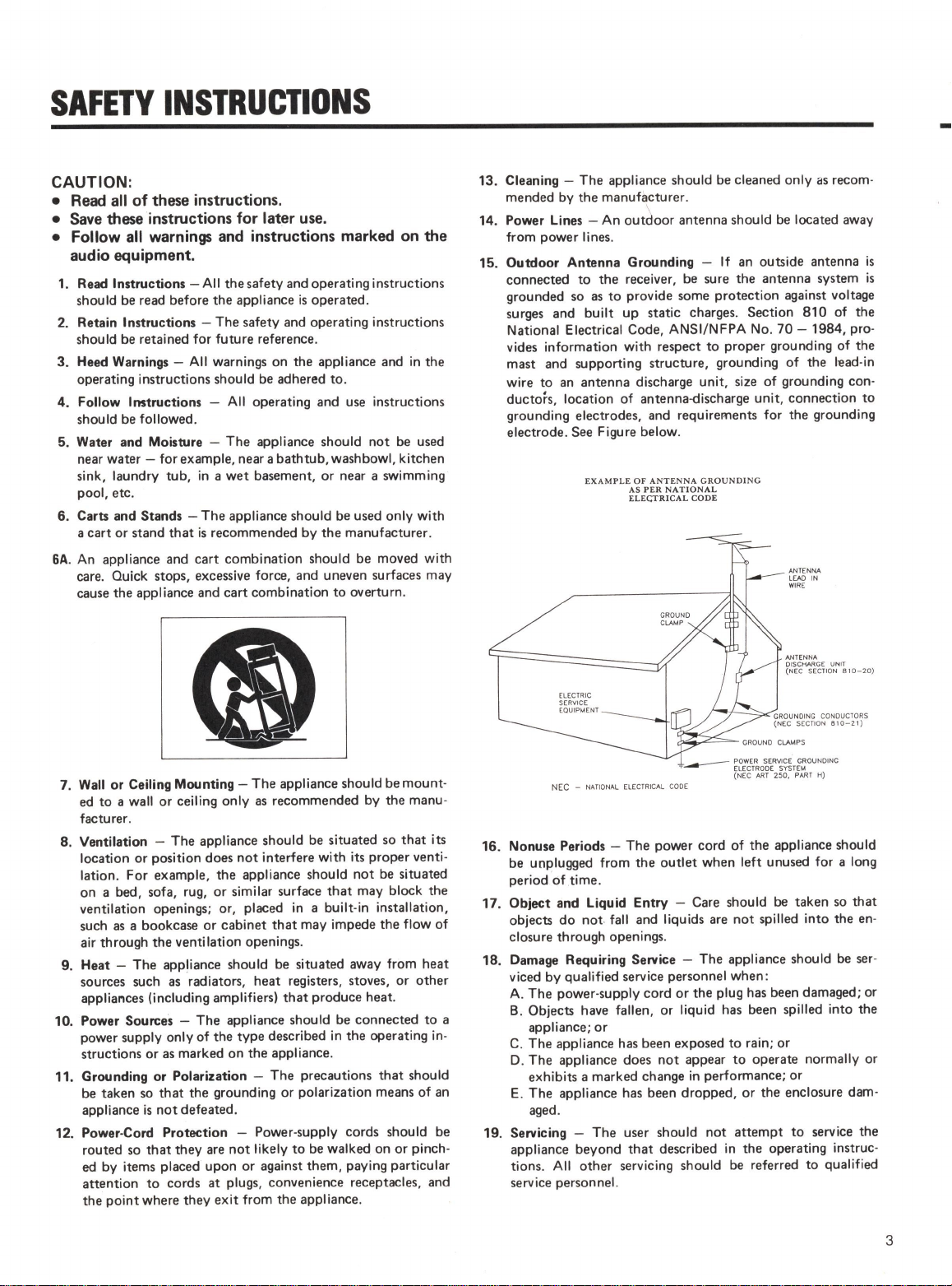
EJECT : Opens the cassette compartment.
3. PITCH CONT : Provides about a plus
or
minus
12
%
variation to the tape speed
in
both Play and Record modes.
Unless you use the function intentionally, make sure that
the knob is at its OFF position for the tape to roll at
nom1al speed (1-7/8 i.p.s. or 4.8 cm/sec.).
4.
REW : Winds the tape at high speed
in
reverse.
If
pressed during Play Pause, enables reverse cueing.
5. F.FWD : Winds the tape at high speed
in
the forward
direction.
If
pressed during Play Pause, enables the forward
cueing.
6. STOP : Stops all tape motion.
7. PLAY : Starts playback.
If
pressed together with
RECORD, starts recording.
If
pressed during Record Pause,
resumes recording.
8. PAUSE : Temporarily stops play
or
recording ; to
resume the function interrupted, press PLAY.
If
pressed
together with RECORD, activates Record Ready mode,
allowing you to start recording
by
pressing PLAY only.
9.
RECORD : Starts recording when pressed together with
PLAY.
10. Tape Counter : Displays the distance from a zero
reference point, selected by pressing RESET (-99 M 59 S
to 99 M 59 S with the 122 MKIII and I I2R
MK.II
;
or
00
00 to 99 99 with the 112
MKII).
A type of tape
in
use (NORMAL, CrO2
or
METAL) is
indicated on the right hand side
of
the tape counter, and the
monitor source
too-"INPUT"
lights unless tape signal
is
feeding the front PHONES and rear OUTPUT.
6
NOTE
122 MKIII and 112R MKII : The tape counter is not a
clock. Its reading depends
on
the tape length, relative
tape packs on both reels and other mechanical
factors. Use a watch to measure the correct length of
particular program.
Discrepancy between measurements on the tape
counter and a clock (from beginning
to
end, one-way
run) :
Normal/CrO2 Metal
C-30 +3 min. 00 sec. to -
4 min. 00 sec.
C-46 +1 min.30 sec. to +2 min.00 sec.to
2 min.45 sec. 3 min.15 sec.
C-60
-45
sec. to +30 sec. Omin.00 sec. to
+1
min.15 sec.
C-90
-1
min.30 sec. to
-1
min.15sec.to
-30
sec. Omin. 00 sec.
C-30/46 measurements made with narrow hub cassettes.
11. INPUTS, L and R : Allow individual control
of
both
channel levels.
122
MKIII
: Both controls are geared together to allow
simultaneous adjustment
of
the record level
of
both
channels. Each channel can be adjusted independently
by
holding one knob and turning the other.
12.
VU
meters : Indicate input
or
tape signal levels
depending on the transport mode and the MONITOR switch
setting.
13. MONITOR : Setting to INPUT routes the input
signal to the PHONES and OUTPUT jacks, whatever the
transport mode.
If
set to AUTO, the input signal can be
monitored in Record Pause (Ready) mode, and the tape
signal while recording (off-tape monitoring)
or
playing.
The VU meters also switch the same way.
The 112
MK.II
does not provide off-tape monitoring ; you'll
hear the input signal instead while recording is taking place.
14. OUTPUT : Adjusts the signal level sent to the
OUTPUTjacks on the rear panel.
www.SteamPoweredRadio.Com
15. MPX FILTER : Por making Dolby recording
of
FM
broadcasts. Without this filter, the pilot tone (
19
Hz) and
subcarrier note (38 kHz) contained in FM programs may
"thwart" the DOLBY NR system.
16. DOLBY NR : Selects the Dolby B
or
C Noise
Reduction system ordefeats them.
17. INPUTS, L and R : These 1/4"
jacks
accept
unbalanced line-level signals.
NOTE
Connecting signals to the front input jacks defeats the
rear input jacks. You cannot use both jacks at one
time.
18. PHONES: The knob adjusts the listening level
in
the
headphones plugged into the adjacent jack.
19. REPEAT : Initiates repeat play between Memo l and
Memo 2 (p.12)
20. MEMO
IN
:
If
pressed together with LOC l
or
2,
stores the current tape point into memory.
a MEMO
IN
cannot operate during repeat play
or
when
the tape is fast-winding as a result
of
pressing either
LOC.
21.
RTZ
: Fast-winds the tape at either direction, stopping
when the tape counter reads
00
00. Inertia may carry the
tape slightly past the
00
00 point.
22. LOC, 1 and 2 : Locate the tape to Memo I and
Memo 2 points, respectively.
23. DIRECTION (112R MKII only) : Switches over
the tape side to play
or
record.
a DIRECTION cannot operate during :
o Repeat play
o Search with LOC
or
CPS
o Fast cueing
o 4-second blank recording
a
If
pressed while in F.FWD
or
REW, switches the tape
side to play (or record) only when the tape reaches the
end
or
beginning or whefl stop is pressed.
24. Auto Reverse (112R MKII only) : In one-time,
auto-reverse mode (
~
), both sides
of
the tape play or
record and stop. But, if play or record starts on the reverse
tape side, only that tape side plays or records and stops.
In continuous reverse mode (
c--.:>
),
the entire tape plays
up
to five times and stops, or both sides
of
the tape record
and stop.
25. ADJUST (122 MKIII only) :
If
pressed when
MONITOR is set to AUTO and the transport is in Record
mode, allows you to press the OSC and
IO
kHz switches
and to "fine tune" the BIAS and LEVEL settings. For more
details, see page
15.
26. OSC and 10 kHz (122 MKIII only) : Pressing
OSC after ADJUST allows you
to
get 400 Hz or lOkHz
oscillator signals for BIAS and LEVEL adjustments (you
get a 400 Hz signal unless you press the
IO
kHz switch).
27. BIAS/LEVEL trimmers (122 MKIII only) : For
precise calibration
of
the bias/record levels to the tape being
used.
7
www.SteamPoweredRadio.Com
O The Rear Panel
28
29 30
32
31
33
32
31
28.
INPUT XLR-type jacks :
Accept
+4
dBm balanced
signals. Pin assignment : Pin 1
is
shield (ground), Pin 2
is
Hot(+), and Pin 3
is
Cold(-).
29. INPUT UNBAL/BAL switch :
Selects either the
XLR-type or RCA input jacks.
30. OUTPUT XLR-type jacks :
Transmit +4 dBm
balanced signals to your mixer, monitor amp, etc. Pin
assignment : Pin I
is
shield (ground), Pin 2
is
Hot (+), and
Pin 3
is
Cold(-).
31. OUTPUT RCA jacks
Transmit
-10
dBV
unbalanced signals.
32. INPUT
RCA
jacks :
Accept -
10
dBV unbalanced
signals.
33. Blank Panel (except 122 MKIII) :
Space for
mounting an optional balanced amp kit (LA-112).
8
0
0
122MKIII
34
112RMll/112MKII
34
When the LA-112 is installed, you who are using the
112R MKil/112 MKII will have access to the INPUT
XLR-type jacks (#28), the INPUT UNBAL/BAL switch
(#29) and the OUTPUT XLR-type jacks (#30) as with the
122
MKIII.
34. REMOTE CONTROL connector :
This 25-pin D-
sub connector is for controlling the transport from the
optional remote RC-112R (for l 12R
MKII)
or RC-134 (for
122
MKIII and 112
MKII),
orfor fader start from a mixer.
A 25-pin connector (Part No. 53363571-00) and its jacket
(Part No. 5336358 I00) are optionally available.
Fader start (122 MKIII and 112 MKII only) : Pins 22 and
24 are assigned for this function. The transport will toggle
Play and Pause, as depicted.
www.SteamPoweredRadio.Com
REMOTE CONTROL
r;:::;,
0000000000000
'()'
~
000000000000
~
PLAY
!
I PIN NO.22
E PIN NO
.2
4
FADER
REMOTE CONTROL Pin Assignment
Pin
1
2
3
4
5
6
7
8
9
10
11
12
13
14
15
16
17
18
19
2)
21
REMOTE CONTROL
0000000000000
000000000000
112RMKIII
122MKlll/112MKll1 t
Signal Function
Activates Jhe
PLAY
IN
corresponding transport y y
mode, active at low level
FFIN " y y
REWIN " y y
PAUSE
IN
" y y
STOP
IN
" y y
RECIN " y y
Lets the next deck start
playing during sequential
STARTCOMMAND play
of
two decks, active at N y
low level (only when
ordered to provide the
function).
Not Used - -
Indicates the tape travel
UP/DOWN OUT direction (UP : forward, y y
DOWN :rewind)
Indicates either end of the
ENDTALLYOUT tape is reached, active at N y
low level.
Indicates the corresponding
F. PLAY TALLY OUT mode is activated, active at y y
low level.
FFTALLYOUT " y y
REWTALLYOUT " y y
PAUSE TALLY OUT " y y
STOP TALLY OUT " y y
RECTALLYOUT " y y
Activates reverse side play,
R.
PLAY
IN
active
at
low level. N y
R.
PLAY TALLY OUT Indicates reverse side play N y
mode, active at low level.
REEL PULSE y y
Not Used - -
R1ZIN Fast-winds the tape to y y
00 00, active at low level.
Pin
22
Z3
24
25
Signal Function
FADER START Closed, Play; opened, y N
Pause
Not Used --
GND
y y
+SV
Max.S0mA y y
Y stands for Yes, N for No.
Input :
To
activate a function, the pin must be brought to
ground potential for 24 msec or more.
Tally
STOP
FAST
F.
PLAY
A.
PLAY
PAUSE
REC
END
Timing of Tally Outs
Key
Operation
I
--~------------------------·~'-
,
400m
SEC
(from
Fast
mode)
I
650m
SEC
(from
Play
mode)
'
____
--
___
-
__
-
___
-
___
-
___
L...---1
-
I
200m
SEC
(from
Stop
mode)
,
BOOm
SEC
(from
Play
mode)
I
--i-450-m-SEC
~rom
Stop-mode)
1
1
1000m
SEC
(from
R.
Play
mode)
200m
SEC
(from
Pause
mode)
'
!----1
- - 1-450~
-SEC
(fiom
Stop
mode)-_..._
__
_
•
1000m
SEC
(from
F.
Play
mode)
I
200m
SEC
(from
Pause
mode)
!---1
-
--1-
300m
SEC-(~om-Stop
mode)_,_
__
_
•
200m
SEC
(from
Play
mode)
!....____,
!
REC
PLAY
50m
SEC
(from
Play
mode)
I
450m
SEC
(from
Stop
mode)
,
REC
PAUSE
20m
SEC
(from
Pause
mode)
I
300m
SEC
(from
Stop
mode)
7------
600m
SEC
9
www.SteamPoweredRadio.Com
Basic Operation
10
Recording
OOl.BY NR MPX FILTER
MONITOR
~
-?
E5
□
E51
o-o
Playback
DOLBY
NR
MONITOR
~
mo
Erasing
a
Tape
If
you are using the 122
MKIII,
first adjust
BIAS
and
LEVEL
as per instructions
on page 15.
1.
Plug the record source into the front
or
rear input jacks.
If
you have plugged the record source into the rear jacks, set the
INPUT
switch
(on rear) to the appropriate position.
2. Set the
DOLBY NR
switch to the desired position, and the
MPX FILTER
switch to OFF unless you intend to record FM broadcasts.
3. Set the
MONITOR
select switch to AUTO.
4. Press and hold
RECORD
and press
PAUSE
to activate Record Ready mode.
5. Start your record source and adjust the
INPUT
controls so that the VU meters
peak at about 0, and adjust the
PHONES
control for a comfortable listening
level.
6. When everything
is
ready, press
PLAY
to start recording.
7. To stop recording, press
STOP.
Or
press
PAUSE
to temporarily stop recording;
to resume recording, press
PLAY.
I. Set the
DOLBY
NR
switch depending on the tape
in
use.
2. Set the
MONITOR
switch to AUTO.
3. To initiate playback, press
PLAY.
Adjust the
OUTPUT
and/or
PHONES
level controls as required.
4. To stop playback, press
STOP.
Or
press
PAUSE
to temporarily stop playback;
to resume playback, press
PLAY.
To erase a cassette tape not by cverwriting, set the
INPUT
controls to
O
and press
RECORD
and
PLA-Y
together.
To quickly erase both sides
of
a tape (except metal tapes), use the optional TEAC
E-2A Bulk Eraser.