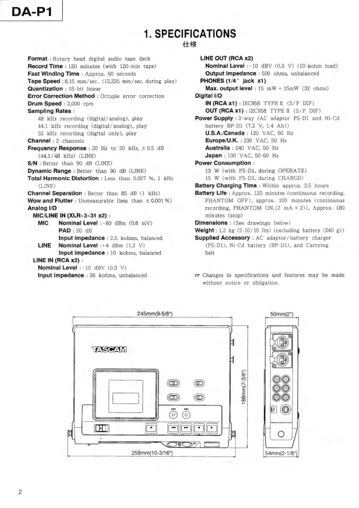
Tascam DA-P1 User manual

TASCAM
TEAC
Professional
Division
SERVICE
MANUAL
DA-P1
Digital
Audio
Tape
Recorder
NOTES
As
regards
the
resistors
and
capacitors,
refer
to
the
circuit
|
[diagrams
and
the
PCB
ass'y
drawings
contained
inthis
manual
*
PC
boards
shown
viewed
from
parts
side.
x
Parts
marked
with
*
require
longer
deliver
time.
+A
Parts
marked
with
this
sign
are
safety
critical
components.
They
must
always
be
replaced
with identical
components
—
refer
to
the
TEAC
Parts
List
and
ensure
exact
replacement.
*
Parts
not
shown
in
the
parts
lists,
or
parts,
though
listed,
having
no
parts
numbers,
are
not
general
"ready-to-supply"
parts.
注意
標準
抵抗
コソ
デン
サー
は
和
省略
し
て
あり
ます
。
回
路
図
お
よび
基板
図
を
参照
し
て
くだ さい
。
1.
プリ
ント
基板
図
は
部
品
面
が
が
され
て
いま
す
。
2.
*
印
の
部品
は
納期
が
若干
か
か
り
ま
す
。
あら
か じ
め ご
了承
くだ
さい
。
з.
Л
印
は
安全
規格
重要
部
品 で
す
。
交換
する
と
き
は
必ず
ティ
アッ
ク
指定
の
部
品 を
使用
し
て
くだ
さい
。
4.
リス
ト
さ
れ
て
いな
い
部
品
は
原則
と
し
て
サー
ビス
供給
部
品
と
し
て
取扱
っ
て
いま
せん
。
Effective
:
September,
1995
4A1571
INSTRUCTIONS
FOR
SERVICE
PERSONNEL
BEFORE
RETURNING
APPLIANCE
TO
THE
CUSTOMER,
MAKE
LEAKAGE
-
CURRENT
OR
RESISTANCE
MEASUREMENTS
TO
DETERMINE
THAT
EXPOSED
PARTS
ARE
ACCEPTABLY
INSULATED
FROM
THE
SUPPLY
CIRCUIT.
D00200000A

DA-P1
1.
SPECIFICATIONS
Format
:
Rotary
head
digital
audio
tape
deck
Record
Time
:
120
minutes
(with
120-min
tape)
Fast
Winding
Time
:
Approx.
60
seconds
Tape
Speed
:
8.15
mm/sec.
(12.225
mm/sec.
during
play)
Quantization
:
16-bit
linear
Error
Correction
Method
:
Octuple
error
correction
Drum
Speed
:
2,000
rpm
Sampling
Rates
:
48
kHz
recording
(digital/analog),
play
44.1
kHz
recording
(digital/
analog),
play
32
kHz
recording
(digital
only),
play
Channel
:
2
channels
Frequency
Response
:
20
Hz
to
20
kHz,
+0.5
dB
(44.1/48
kHz)
(LINE)
S/N
:
Better
than
90
dB
(LINE)
Dynamic
Range
:
Better
than
90
dB
(LINE)
Total
Harmonic
Distortion
:
Less
than
0.007
%,
1
kHz
(LINE)
Channel
Separation
:
Better
than
85
dB
(1
kHz)
Wow
and
Flutter
:
Unmeasurable
(less
than
+
0.001%)
Analog
I/O
MIC/LINE
IN
(XLR-3-31
x2)
:
MIC
Nominal
Level
:-60
dBm
(0.8
mV)
PAD
:
20
dB
Input
impedance
:
2.5
kohms,
balanced
LINE
Nominal
Level
:+4
dBm
(1.2
V)
Input
impedance
:
10
kohms,
balanced
LINE
IN
(RCA
x2)
:
Nominal
Level
:-
10
dBV
(0.3
V)
Input
impedance
:
35
kohms,
unbalanced
245mm(9-5/8")
仕様
LINE
OUT
(RCA
x2)
Nominal
Level
:-10
dBV
(0.3
V)
(10-kohm
load)
Output
impedance
:
500
ohms,
unbalanced
PHONES
(1/4^
jack
x1)
Max.
output
level
:
15
mW
+
15mW
(32
ohms)
Digital
1/0
IN
(RCA
x1)
:
IEC958
TYPE
II
(S/P
DIF)
OUT
(RCA
x1)
:
IEC958
TYPE
Il
(S/P
DIF)
Power
Supply
:
2-way
(AC
adaptor
PS-D1
and
Ni-Cd
battery
BP-D1
(7.2
V,
1.4
Ah))
U.S.A./Canada
:
120
VAC,
60
Hz
Europe/U.K.
:
230
VAC,
50 Hz
Australia
:
240
VAC,
50
Hz
Japan
:
100
VAC,
50-60
Hz
Power
Consumption
:
13
W
(with
PS-Dl,
during
OPERATE)
15
W
(with
PS-D1,
during
CHARGE)
Battery
Charging
Time
:
Within
approx.
2.5
hours
Battery
Life
:
Approx.
120
minutes
(continuous
recording,
PHANTOM
OFF),
approx.
100
minutes
(continuous
recording,
PHANTOM
ON,(2
mA
x
2)),
Approx.
180
minutes
(stop)
Dimensions
:
(See
drawings
below)
Weight
:
1.2
kg
(2-10/16
Ibs)
(excluding
battery
(240
g))
Supplied
Accessory
:
AC
adaptor/battery
charger
(PS-D1),
Ni-Cd
battery
(BP-D1),
and
Carrying
belt
tr
Changes
in
specifications
and
features
may
be
made
without
notice
or
obligation.
50mm(2")
|
fx
258mm(10-3/16")
5
5
~
E
E
$
8
54тт(2-1/8"

DA-P1
2.
TEST
MODES
テス
トモ
ー
ド
2-1.
Accessing
and
Exiting
the
Test
Modes
.
Set
the
CHARGE/OPERATE
switch
to
OPERATE.
2.
Hold
down
STOP,
F
FWD
and
REW
and
slide
the
POWER
switch
to
the
right.
The
deck
enters
Block
Error
Rate
Measurement
mode,
as
confirmed
by
the
indication
of
"br"
appearing
in
the
PGM
NO.
display.
From
this
mode
only
you
can
access
the
other
test
modes,
as
discussed
below.
3.
To
disable
all
test
modes,
turn
off
the
deck.
2-2.
Block
Error
Rate
Measurement
Mode
This
mode
counts
Cl
errors
occurring
in
128
PCM
data
blocks
per
track,
and
displays
the
number
of
errors
per
10000
blocks
(near
to
9984,
the
actual
number
of
blocks
occupied
by
78
tracks).
.
If
you
have
changed
the
"br"
to
other
test
mode
indications
per
instructions
given
below,
press
MARGIN
RESET.
The
"br'
will
reappear
in
the
PGM
NO.
display
window.
.
Play
back
a
tape.
The
numbers
appearing
in
the
tape
counter
section
represent
the
Block
Error
Rate.
(A
broken
line
is
displayed
when
the
transport
is
in
any
other
modes
than
play.)
3.
Each
time
you
press
MARGIN
RESET,
the
tape
counter
display
switches,
as
confirmed
by
the
MARGIN
display
being
changed
as
follows
in
sequence
:
№
"AH"
(block
error
rate
read
by
head
A)
"bH"
(block
error
rate
read
by
head
B)
"Ab"
(block
error
rate
read
by
heads
A
and
B)
2-3.
Mechanical
Test
Mode
.
Load
a
function
test
tape
(TY-7551).
.
When
the
transport
is
in
STOP,
press
ID
SELECT.
"mtES
will
appear
in
the
tape
counter.
.
Play
back
the
tape.
PASS"
will
appear
in
the
tape
counter
section
if
there
is
no
error
detected
in
the
mechanism.
Otherwise,
the
following
messages
will
appear
instead,
depending
on
error
(if
two
errors
or
more
occur,
the
corresponding
messages
will
appear
in
order,
each
for
3
seconds).
м
о
Err01
(Mechanism
loading
check
1):
LMS4
(U320-22
on
MAIN
PCB)
didn’t
go
LOW
when
STOP
switched
over
to
PLAY.
Err02
(Mechanism
loading
check
2)
:
LMS1
(U320-19
qn
MAIN
PCB)
didn’t
go
HIGH
when
STOP
switched
over
to
PLAY.
Err03
(DFG
pulse input
check)
:
Drum-
ON
signal
transmitted,
but
no
DFG
pulse
detected
(TP337
on
MAIN
PCB).
2-1.
テ
スト
モー
ド
起
動
プ
終了
方
法
1.
テス
トモ
ー
ド
起動
1).
CHARGE/OPERATE
スイ
ッ
チ
を
OPERATE
側
に
する
。
2).
STOP
キー、F
FWD
キー、REW
キ
ー
を
押し
な が ら 、
POWER
スイ
ッ
チ
を
右
に
スラ
イド さる
。
この
と
き
、PGM
NO.3
“br"
と
表示
し
、
テ
スト
モー
ド
に
な
り
ま
す
。
こ
の
状態
か
ら
、
2-2
項
以下
に
述べ
る
各
テ
スト
モー
ド
に
移行
し
ます
。
2.
テス
トモ
ー
ド
終了
電源
を
OFF
に
する
と
、
テ
スト
モー
ド
は
終了
し
ます
。
2-2.
Block
Error
Rate
計
測
モ
ー
ド
この モー
ド
で
は
、1
ト
ラッ
ク
当
り
128
ブ
ロッ
ク
あ
る
PCM
デ ー タ
ブ
ロッ
ク
の
“C1
エ
ラー"
を
レー
ト
と
し
て
見
られ
る
よう
に
、10000
ブ
ロッ
ク
に
近似
し た
78
ト
ラッ
ク
分
の
9984
ブロ
ッ
ク
当
り
の
エラ
ー を
カウ
ント
し
て
表示
し
ます
。
1.
MARGIN
RESET
ス
イッ
チ
を
押し
て
、PGM
NO.
表示
部
に
“
br"
を
表示
させ
る
。(
テ
スト
モー
ド
起
動
時
は
、
こ
の
モー
ド
に
セッ
ト
さ
れ
ま
す
。)
2.
テー
プ
を
再生
し
た
と
き
、
テ
ー
プ
カウ
ンタ
ー
部
に
表示
され
る
値 が
Block Error
Rate
C,
(PLAY
MEAM,
"—
-"&
示
と
な
り
ま
す
。)
3.
MARGIN
RESET
スイ
ッ
チ を
押す
ご
と
に
、MARGIN
表示
部
の
表
示
が
以下
の 順 で
変わ
り
ます
。
“AH”:
AN»
FO4OBlock
Error
Rate
“bH”
:
BA
>
FO4OBlock
Error
Rate
“Ab”:
A,
BA
>
Ffiitt?:
Block Error
Rate
2-3.
メ
カテ
スト
モー
ド
1.
フ
ァ
ン
クシ
ョ
ン
・
テ
ー
プ
(TY-7551)
を
装着
する
。
2.
STOP
状
態
で
、ID
SELECT
キ
ー を
押す
と
、
テ
ー
プ
カウ
ンタ
ー
部
に
“mtESt"
と
表示
し
ます
。
3.
この
状態
で
テー
プ
を
再生
する
と
、
メ
カ に
異常
が な い
場合
は
テー
プ
カ
ウ
ンタ
ー
部 に
“PASS
"
と
表示
し
ます
。
異常
が
検出
され
た
場合
は
、
そ
の
内
容
に
応じ
て
Erm01~Err11
の
表
示
を
行い
ます
。
(複数
の
エラ
ー
の
と
き
は
、
数
字
の
小さ
しい
順に
3
秒
ずつ
表示
し
ます
。)
エラ
ー
の
内
容
は
以下
の
通り
で
す
。
Er01
(メカ
ロー
ディ
ング
チェ
ッ
ク
1):
STOP
か
ら
PLAY
移行
時
に
LMS4
(MAIN
PCB
の
U320-22)
が
"LOW"
に
な
ら
な
か
っ
た
。
Er02
(メカ
ロー
ディ
ング
チェ
ッ
ク
2)
:
STOP
か
ら
PLAY
移行
時
に
LMS1
(MAIN
PCB
の
U320
-19)
が
“HIGH"
に
な
ら な か
っ
た 。
Er03
(DFG
パ
ルス
入力
チェ
ッ
ク
)
:
“ラム
ON
信号
が
出力
され
て
いる
の
に
、DFG
(MAIN
PCB
の
TP337)
の
パル
ス
が
検出
され
な い
。
Err04
(DLOCK
信
号
人
力
チェ
ッ
ク
)
:
ドラ
ム
が
回
転
し
て
も
、DLOCK
(MAIN
PCB
の
TP345)
が
“HIGH"
に
な
ら
な
い
。

DA-P1
Err04
(DLOCK
signal
input
check)
:
DLOCK
(TP345
on
MAIN
PCB)
doesn't
go
HIGH
whereas
the
drum
is
in
fonction.
Err05
(CFG
pulse
input
check)
:
Capstan-
ON
signal
transmitted,
but
no
CFG
pulse
detected
(TP339
on
MAIN
PCB).
Err06
(CRLOCK
signal
input
check)
:
CRLOCK
(TP344
on
MAIN
PCB)
doesn't
go
HIGH
whereas
the
the
capstan
motor
is
in
function.
Err07
(Supply
reel
pulse input
check)
:
No
supply
reel
pulse
fed
into
U327-63
(FGS)
on
MAIN
PCB
whereas
the
tape
is
in
motion.
Err08
(Takeup
reel
pulse input
check)
:
No
takeup
reel
pulse
fed
into
U327-62
(FGT)
on
MAIN
PCB
whereas
the
tape
is
in
motion.
Errog
(RF
signal
input
check)
:
No RF
signal
detected
(TP346
on
MAINPCB)
in
Play
mode.
Er10
(PLLLOCK
signal
input
check)
:
PLLLOCK
(TP346
on
MAIN
PCB)
doesn't
go
HIGH.
(Actually,
the
message
looks
lik
По
Errt1
(Recognition
hole
check)
:
Not
all
of
RH2
to
RH4
(U320-23
to
25)
gone
LOW.
(Actually,
the
message
looks
like
д
*
If
you
let
the
tape
play
continuously
after
completion
of
the
above
mechanism
checks,
the
tape
automatically
switches
to
rewind
when
encountering
the
EOT,
and
restarts
playing
when
encountering
the
BOT.
"Р"
will
appear
in
the
PGM
NO.
display
when
the
EOT
is
encountered
for the
first
time
and
the
tape
counter
will
read
“0001”.
The
sequence
play-rewind
repeats
until
you
stop
the
tape
for
endurance
test,
etc.
Each
time
the
tape
finds
the
EOT,
the
reading
on
the
tape
counter
counts
up.
Pressing
ID
SELECT
will
reset
the
counter
to
“0000”.
2-4.
SW
Test
Mode
Perform
the
following
steps
with
no
tape
loaded.
.
Press
LIGHT,
The
PGM
NO.
display
will
read
"rd"
to
show
that
the
switch
tests
are
ready.
2.
Press
all
the
followings
keys
one
by
one
(each
time
a
key
is
pressed,
the
indication
shown
in
parentheses
will
appear
in
the
tape
counter
section)
:
COUNTER
MODE
(F5),
RESET
(F2),
MARGIN
RESET
(F4),
ID
SELECT
(F3),
PAUSE
(F6),
REC
(F7),
EJECT
(S2),
STOP
(t1),
PLAY
(t2),
F
FWD
(t6),
REW
(t5),
PP
(t4)
and
М
(13).
3.
Slide
the
HOLD
(F8),
Fs
(t8),
and
INPUT
(t7)
switches
to
the
right
or
left.
^
4.
Press
LIGHT
once
more.
PASS"
will
be
displayed
in
the
tape
counter
section
if
there
is
no
error
detected.
If
you
press
LIGHT
without
previously
pressing
or
sliding
all
the
keys
or
switches
enumerated
above,
an
error
message
will
be
displayed
(for
example
:
"Er
F8"
if
HOLD
was
not
pressed).
Er05
(CFG
パル
ス
入
力
チェ
ッ
ク
)
:
キャ
プス
タン
ON
信号
が
出力
され
て
いる
の
に
、CFG
(MAIN
PCB
の
TP339)
の
パル
ス
が
検出
され
な い
。
Епоб
(CRLOCK
信
号
人
力
チ
ェ
ッ
ク
)
:
キャ
プス
タン
・
モ
ー
タ
が
回
転 し
て も
、CRLOCK
(MAIN
PCB
の
TP344)
が
“HIGH"
に
な
ら
な い
。
Em07
(サプライ
リー
ル
・
パ
ルス
入力
チェ
ッ
ク
)
:
テー
プ
が
走行
し て
いる
の に
、MAIN
PCB
の
U327
-63
(FGS)
に
サプライ
リー
ル
・
パ
ルス
が
入力
され
な い
。
Err08
(テイ
クア
ッ
プ
リー
ル
・
パ
ルス
入力
チェ
ッ
ク
)
:
テー
ブ
プ
が
走行
し て
いる
の
に
、MAIN
PCB
の
U327
-62
(FGT)
に
テイ クア
ッ
プ
リー
ル
・
パ
ルス
が
入力
され
な
い
。
Err09
(RF
信号
入力
チェ
ッ
ク
)
:
再生
状態
で
、RF
信
号
(MAIN
PCB
の
TP343)
が
検出
で
き
な
い
。
Er10
(PLLLOCK
信号
入力
チェ
ッ
ク
)
:
PLLLOCK
(MAIN
PCB
の
TP346)
が
"HIGH"
に
な
ら
な
い
。
注
).
実際
に
は
、Err
1
の
よう
に
表示
し
ます
。
Er11
(レコ
グ
ゲニ
ショ
ン ホ
ー
ル
・
チ
ェ
ッ
ク
)
:
RH2-RH4
(MAIN
PCB
の
U320-23-25)
が
、
すべ
て
“LOW”
に
な
っ
て
いな
い
。
注
).
実際
に
は
、EFrr
『『
の
よう
に
表示
し
ます
。
*※
上
記
メ
カテ
スト
終了
後
、PLAY
を
続行
し
BOT
を
検出
し
た
場合
、
自動
的
に
BOT
まで
テー
プ
を
巻き
戻し
再度
PLAY
を
開始
し
ます
。
この
と き
、PGM
No.
表
示
部
に
は
“TP"
と
、
テ
ー
プ
カウ
ンタ
ー
部
に
は
“0001”
と
表示
し
ます
。(EOT
を
検出
する
た
びに
テー
プ カ
ウン
ター
部
の
表示
は
カウ
ント
・
ア
ッ
プ
し
ます
。)
これ
は
、
耐
久
テ
スト
等
の
カウ
ント
に
使用
し
ます
。
また
、ID
SELECT
キ ー を
押す
と
、
テ
ー
プ
カウ
ンタ
ー
部
の
表示
を
"0000"
に
リセ
ッ
ト
し
ます
。
2-4.
SW
テス
トモ
ー
ド
テー
プ
が
入っ
て
いな
い
状態
で 、
実
施し
て
くだ
さい
。
.
LIGHT
キー
を
押す
と
、PGM
NO.
表
示
部
に
"rd"
と
表示
し
、SW
テス
トモ
ー
ド
に
な
り
ま
す
。
LIGHT
キー
以外
の
キー
すべ
て
[COUNTER
MODE
キー
(F5S)
、
RESET
キー
(F2)、MARGIN
RESET
キー
(F4)、ID
SELECT
キー
(F3)、PAUSE
キ
ー
(F6)、REC
キ
ー
(F7)、EJECT
キ
ー
(S2),
STOP+-
(1),
PLAY+-
(12),
FFWD+-
(16),
ВЕМ/4--
(15),
ьр12--
(⑭)、
還
コキ
ー
(3)]
を
押し
ます
。
この
と
き
、
押
され
た
キー
が
カウ
ンタ
ー
部
に
表示
され ます
。
例え
ば
、COUNTER
MODE
キー
を
押し
た
場合
は
F5
と
表示
され
ます
。
次
に
スラ
イド
・
ス
イッ
チ
HOLD
スイッチ
(F8)、Fs
スイ
ッ
チ
(8)、INPUT
ス
イッ
チ
(⑰7)]
を
どちら
か
に
切り
替え
て
くだ
さい
。
L
最後
に
LIGHT
キー
を
押し
ます
。
こ
の
と
き
、
テ
ー
プ
カウ
ンタ
ー
B
に
“PASS"
と
表示
され
れ
ば
、
テ
スト
は
合格
で
す
。
も
し
、
上
記
の
キー
お
よび
スイ
ッ
チ
が
すべ
て
押さ
れず
(スラ
イド
され
ず
)
に
LIGHT
キー
が
押さ
れ
た
場合
に は
、“Er
F8"
(HOLD
スイ
ッ
チ
が
スラ
イド
され
な
か
っ
た
)
の
よう
な
表示
を し
ます
。
У
ө
=

2-5.
LCD
Display
Test
Mode
Press
COUNTER
RESET.
All
indications
in
the
LCD
display
window
will
go
out,
then
a
set
of
indications
will
light
up
then
turn
off.
All
the
sets
of
indications
will
do
so
in
sequence.
Finally,
all
the
indications
are
light
up
at
once
to
show
that
the
tests
are
complete.
If
you
hold
down
COUNTER
RESET
while
the
test
is
taking
place,
the
display
at
that
moment
"freezes."
It
"unfreezes"
when
you
release
the
key.
2-6.
System
Data
Display
Mode
1.
To
activate
this
mode,
press
COUNTER
MODE.
2.
Each
time
you
press
COUNTER
MODE,
the
following
data
will
be
displayed
in
sequence
:
@
Version
Number
Example
:
"ur"
”01m00”
@
Category
Code
Data
These
data
are
available
only
when
a
digital
signal
is
plugged
into
the
DIGITAL
IN
terminal
and
the
Input
Monitor
Mode
is
activated.
for
Version
01.00
"се
"CO"
for
DAT
;
"Ci"
for
DAT-P
;
"80"
for
CD.
€
Cbit
Data
These
data
are
available
only
when
a
digital
signal
is
plugged
into
the
DIGITAL
IN
terminal
and
the
Input
Monitor
Mode
is
activated.
Check
each data
by
converting
sexadecimal
4
digits
appearing
in
the
display
into
binary
data
as
detailed
below.
Sexadecimal
Data
Binary
Data
16
進
デー
タ
7—9
2187-7
“Cb”
"X
X
X
X”
:
Plul
LOCK
:
Plul
UNLOCK
0
1
0
:
PARITY
Good
1
:
PARITY
NG
0
:
Consumer
use
1
0
1
:
Broadcasting
studio
use
:
Normal
audio
mode
:
Non
audio
mode
Digital
copy
prohibited
Digital
copy
permited
0
ТТТ
9°:
1:
|
0
0 0
:
Preemphasis
off
1
00
:
50/15
us
preenphasis
DA-P1
2-5.
LCD
表示
テス
トモ
ー
ド
COUNTER
RESET
キ
ー
を
押す
と
、
こ
の
テス
ト
が
開始
され
下記
を 自
動
的
に
行い
ます
。
まず
表示
が
すべ
て
消灯
し た
後
、
い
くつ
か
の
ブロ
ッ
ク
毎
に
点灯
消
灯
を
繰り
返し
、
最
後に
表示
が
全
灯
し
て
テス
ト
終
了
と
な り ま す
。
*
テ
スト
中
に
COUNTER
RESET
キー
を
押す
と 、
そ
の
と き
の
表示
の
まま
止め
る
こと
が
で
きま
す
。(
離
す
と
テス
ト
を
継続
し
ます 。)
26.
シス
テム
情報
表示
モー
ド
1.
COUNTER
MODE
キー
を
押す
と
、
こ の
モー
ド
に
な
り
ま
す
。
2.
この
モー
ド
中
、COUNTER
MODE
キ ー
を
押す
ご
と
に
、
以下
の
表
示
を
順に
行い
ます
。
ョ
ン
表
示
“01т00”
:
Ver.
01.00
を
表し
ます
。
⑯
カテ
ゴリ
ー
コ
ー
ド
情報
表示
デジ
タル
信号
が
DIGITAL
IN
端子
に
入力
され
て
いて
、
イ
ンプ
ブッ
ト
・
モ
ニタ
ー・
モ
ー
ド
状態
で
表示
し
ます
。
“ot”
“co”
:DAT
“С1”
:DAT-P
“80”
:CD
@
Cbit
情
報
表示
デジ
タル
信号
が
DIGITAL
IN
端子
に
入力
され
て
いて
、
イ
ンプ
ッ
ト
・
モ
ニタ
ー・
モ
ー
ド
状態
で
表示
し
ます
。
以下
の
よう
に
、
表示
され
る
16
進
4
桁
を
2
進
デ
ー
タ
に
変換
し て
各
情報
を
確認
し
ます
。
民生
用
プロ
用
オー
ディ
オデ
ー
タ
オー
ディ
オデ
ー
タ
以外
コピ
ー
禁
目
コピ
ー
許
可
プリ
エン
ファ
シス
無し
ブリ
エン
ファ シス
有り
0
:
44.1kHz
1:48kHz
)
Fs
1
TT
0
0:
Fixed
固定
000
000
001
00:N
標準
モー
ド
0
1:Variable
pitch
shifted
mode
可変
ピッ
*)
10:
High
accuracy
mode
1
:
32kHz
lormal
accuracy
mode
Clock
accuracy
RISE
クロ
ッ
ク
精
度

DA-P1
@
System
Data
Data
recorded
on
the
tape
and
the
setting
status
of
Digital
Copy
Mode
are
displayed
(the
5-digit
numbers
displayed
are
binary
data.)
Reference).
ID6
is
represented
by
00
when
Copy
Free
⑯
シス
テム
情報
表示
ー
プ
上
に
記録
され
て
いる
情報
お
よび
Digital
Copy
Mode
の
設定
状態
を
表示
し
ます
。
(表示
され
る
5
桁
の
値
は
2
進
デ
ー
タ
で
す
。)
参考
).
Copy
Free
Mode
の
と
き
、ID6
は
00
を
記録
し
ます
。
Моде
is
selected.
"Sy"
"XXXXX"
|
0:SCMS
mode
(mounted
D806
on
FRONT
PCB)
1:Copy
Free
mode
(no
mounted
D806
on
FRONT
PCB)
9
508
>
Emphasis
エン
ファ
シス
O
:
Normal
track
ノー
マル
トラ
ッ
ク
"
=
^
Lo
Wide
track
74
EP397
)
Tack
pitch
トラ
ッ
ク
ピ
ッ
チ
0
0:Permitted
コピ
ー
許
可
1
0:
Prohibited
コピ
ー
禁
止
ID6
1
1:
Special
1
回
の
み
コ
ピー
許可
@
Pack
Item
No.
O
Pack
Item
No.
表示
Shows
the
pack
item data
on
the
tape.
“P1”
"X
XX
X
X”
“x
Xx"
*
About
the
Pack
A
maximum
of
7
data
called
the
Pack
can
be
recorded
in
the
subcode
area
of
the
tape.
(A
data
of
8
byte
x
8
is
handled
as
one
Pack).
Generally,
the
same
Pack
data
is
recorded
for
each
track.
It is
only
variable
depending
on
deck
and
manufacturer.
(Refer
to
next
page.)
The
Pack
contains
the
following
7
main
item data
:
Item
No.
1
:
Program
Time
2
:
Absolute
Time
:
Pro
DAT
Time
(Time
Code)
:
TOC
:
Date
:
Catalog
Number
:
Pro
binary
(for
profesional
use)
o
の
の
ょ
の
Т
-әшыло-
テー
プ
ブ
に
記録
され
て
いる
Fack
Item
情報
を
表示
し
ます
。
Pack
No.
Pack
No.
Раск
Мо.
Раск
Мо.
Раск
Мо.
Раск
Мо.
Раск
Мо.
*
Pack
に
つい
て
サブ
コー
ド
の
中
に
は
、
Pack
と
呼ば
れる
情報
が
最大
7Pack
記
録
で
きる
よう
に
な
っ
て
いま
す
。(Pack
情
報
は
、8byte
x8
で
1Pack
と
し
て
扱わ
れ
ます
。)
通常
Pack
に
は
、
毎
トラ
ッ
ク
同
じ
内
容
が
記録
され
ます
が
、
メ
ー
カ
ー、
機種
に
より
記録
する
情報
は
お
お
よそ
固定
と
な
っ
て
い
ます
。
(次
ペー
ジ
参
照
)
また
、
情報
の
種類
(Item
No.)
は
、
下
記 の
7
つが
主
に
記録
さ
れ
て
いる
も
の
で
す
。
Item
No.1
:
Program
Time
2
:
Absolute
Time
3
:
Pro
DAT
Time
(Time
Code)
4
:
TOC
5
:
НН
6
:
カタ
ログ
番号
8
:
プロ
バイ
ナリ
ー
(業務
用 )

DA-P1
Pack
Item
Data
Used
on
Some
Different
Decks
:
機種
別 の
Pack
Item
情報
例
*РА-Р1,
РА
-
30
:21---
--
・DA-P1,
DA-30
:21---
--
*
DA-60
:2238-
--
*
DA-60
:2288-
--
*
DA-20
:2----
--
*
DA-20
:2----
--
*
DTC690
(Sony)
:22211
55
+
DTC690
(Sony)
122211
55
•
РСМ7050
(Sony)
:33333
88
+
PCM7050
(Sony)
:33333
88
+
TY-7551
(Test
Tape)
:22114
46
+
TY-7551
(Test
Tape)
:22114
46
@
Power
Supply
(Battery)
Voltage
Indication
0
電源
(バッ
テリ
ー)
電圧
表示
Shows
the
voltage
value
the
РА-Р1
is
currently
fed
DA-P1
に
供給
し て
いる
電源
電圧
値
を
表示
し
ます
。
with.
“ы”
^7H200"
:7.2V
を
表し
ます
。
Example
:
"bt"
"7H20u”
for
7.2
V.
日付
表示
@
Date
Indication
ソフ
トウ
ェ
ア
が
最後
に
変更
され
た
日
付 を
表示
し
ます
。
Shows
the
date
on
which
the
software
has
lastly
been
modified
:
“dt”
“50608”
:1995.06.08
を
表し
ます
。
Example
:
"dt"
"50608"
for
95
(year),
06
(month),
08
(day).

DA-P1
3.
MICROCOM.
(U320
on
MAIN
PCB)
REPLACEMENT
マイ
コン
(MAIN
PCB
U320)
の
交換
3-1.
Removal
.
Refer
to
Figure
3-1
and
using
a
pair
of
tweezers
unhook
the
socket
cover
(it
is
hooked
at
four
points
per
side),
then
lift
the
socket
cover
off.
Note
:
Be
careful
NOT
to
scratch
the
printed
circuits
beneath
with
the
tweezers.
2.
Remove
the
microcomputer.
3-2.
Installation
Install
the
replacement
microcomputer
by
matching
the
pin
numbers,
and
replace
the
socket
cover.
Note
:
Firmly
push
the
socket
cover
until
it
is
snapped
in
place.
3
'
Tweezers
ビ
ピンセット
Socket
Cover
ソケット
・
カ
パー
Fig.
3-1
3-1.
取り
外し
1.
図
3-1
の
よう
に
ピン
セッ
ト
を
ソケット
・
カ
バー
の
穴
に
差し
込み
ソケット
・
カ
バー
の
中
心
方
向
に
倒す
よう
に
し
て
、
ソ
ケッ
ト
・
カ
バー
の
ロッ
ク
部
を 4
面
、
順
に
少し
ずつ
外し
て
、
ソ
ケッ
ト
・
カ
バ
ー
を
外す
。
注意
).
PCB
の
パタ
ー
ン
を
傷つけ
な
いよ
う
【
2.
マイ
コン
を
外す
。
E
意
する
こと
。
3-2.
取り
付け
ピン
番号
を
合わ
せ
て
マイ
コン
を
置き
、
ソ
ケッ
ト
・
カ
バー
を
か
ぶせ
る
。
注意
)。
ソケット
・
カ
バー
の
ロッ
ク
部
が
4
面
と
も
、
し
っ
か
り
ロ
ッ
ク
す
る
まで
ソケット
・
カ
バー
を
押し
込む
こと
。
Microcom.

DA-P1
4.
REMOVAL
OF
MECHANICAL
PARTS
機構
部
品
の
外し
方
This
section
primarily
shows
the
disassembly
procedure
:
to
reassemble,
reverse
the
procedure.
4-1.
Cautions
in
handling
the
mechanism
ass’y
.
When
lifting
the
mechanism
ass'y,
do
NOT
hold
both
edges
with
one
hand;
hold
the
right
and
left
edges
of
the
chassis
with
two
hands.
2.
Do
NOT
touch
the
head
drum.
3.
After
removing
the
mechanism
ass'y,
always
place
it
with
its
right
side
up.
Tf
it
must
be
placed upside
down
for
any
reason,
place
a
protective
sheet
such
as
bubble
packing,
etc.
underneath
to
protect
the
exterior
of
the
cassette
holder.
4.
Do
NOT
touch
the
tip
of
the
flexible
PC
board.
Also
do
NOT
pull
or
bend
it
strongly.
5.
Do
NOT
lift
the
mechanism
ass'y
by
the
flexible
PC
board
or
leads.
6.
Do
NOT
touch
the
guide
roller
with
your
bare
hands.
To
clean
dirt
or
dust
off
the
roller,
wipe
it
gently
with
a
cotton
swab
moistened
with
alcohol.
7.
Do
NOT
touch
the
portions
of
the
posts
which
come
into
contact
with
the
tape.
8.
Do
NOT
touch
the
rubber
portions
of
the
pinch
roller
or
belt
and
the
felt
portion
of
the
tension
band,
etc.
with
greasy
fingers.
9.
Do
NOT
touch
the
pulley
over
which
the
belt
is
hooked
with
greasy
fingers,
etc.
10.
If
a
screw
secured
with
screw
—
locking
compound
is
removed,
reapply
the
compound
after
reinstalling
it.
Tightening
screws
with
too
much
torque
may
strip
the
screw
threads;
be
careful.
11.
When
removing
the
coil
spring,
take
care
so
that
the
hook
is
NOT
deformed.
12.
When
the
head
becomes
dirty,
use
a
cleaning
tape.
13.
When
reassembling,
take
care
NOT
to
let
leads
or
cables
be
pinched
by
the
chassis,
etc.
14.
Do
NOT
touch
the
surface
of
the
drum
with
which
the
tape
comes
into
contact.
15.
When
lifting
the
drum,
hold
both
sides
of
its
base.
16.
When
placing
the
drum
on
a
work
bench,
place
it
on
a
soft
mat
so
that
no
load
or
impact
is
applied
to
the
rotor
of
the
drum
and
motor.
17.
Do
NOT
lift
the
drum
by
its
leads.
18.
Do
NOT
perform
any
soldering
near
the
drum.
19.
Do
NOT
apply
an
external
force
to
the
upper
drum.
20.
Do
NOT
let
the
tip
of
a
screwdriver
or
metallic
object
come
into
contact
with
the
rotor.
Especially
magnets
(or
magnetized
objects)
should
NOT
be
brought
close
to
the
rotor.
21.
Do
NOT
touch
“the
PG
sensor
with
your
fingers.
22.
Do
NOT
lift
the
motor
by
the
flexible
PC
board.
この
項
で
は
外し
方
を
主
に
記述
し
ます
が
、
組
立
は
分
解
の
逆
の
手順
で
行なっ
て
下さ
い
。
41.
メカ
ニズム
Ass'y
取扱
上
の
注意
1.
メカ
ニズム
1).
メカ
ニズム
Ass'y
を
掴む
と
き
は
、
片手
で
両側
を
強く
掴ま
な
い
こと
。
シ
ャ
ー
シ
の
左右
の
端 を
両手
で
掴む
こと
2).
シリ
ンダ
ー
の
ドラ
ム
部
に
は
、
手
を
触れ
な
いこ
3).
メカ
ニズム
Ass'y
を
置く
と
き
は
、
衝
撃
を
与え
な
いよ
うに
置く
こと
。
ま
た
、
メ
カニ
ズム
Assy
は
通常
方
向 に
置く
こと
と
し
、
や
む
お え
ず
逆さ
ま
に
置
く
場合
は
、
下
に
エア
・
パ
ッ
キ
ン
等
保護
材
を
敷き
、
カ
セッ
ト
・
ホ
ル
ダ
ー
の
外装
部
品 を
保護
する
こと
。
4).
フレ
キ
の
先端
部
に
手
を
触れ
な
いこ
と 。
ま
た
、
フ
レキ
を
強く
引
っ
張っ
た
り
曲
げた
り
し
な
いこ
と
。
5).
フ
レキ
ま
た
は
リー
ド
線
を
持っ
て
、
メ
カニ
ズム
Ass'y
を
持ち
上
げ
な
いこ
と
。
6).
ガイ
ド
・
ロ
ー
ラ
ー
の
ロー
ラー
に は 、
手
で
触ら
な
いこ
と
。
汚れ
を
拭く
と
き
は
、
ア
ルコ
ー
ル
を
綿棒
に
浸し
て
軽く
拭く
こ
と
。
т).
各
ポ
スト
の
テー
プ
走
行
面 に は
、
手
で
触ら
な
いこ
と
。
ピン
セッ
ト
や
ドラ
イ
バ
ー
等
で
傷
を
付け
な
いこ
と
。
ま
た
、
磁
化
され
た
ピン
セッ
ト
,
ドラ
イ
バ
ー
で
触ら
な
いこ
と
。
8).
ピン
チロ
ー
ラ
ー,
ベル
ト
等
の
ゴム
部
、
テ
ンション
・
バ
ンド
等
の
フェ
ルト
部
に
油
の
つい
た
手
で
触ら
な
いこ
と
。
・
ベ
ルト
の
か
か
る
プー
リー
等
に
グリ
ス
の
付い
た
手
で
触ら
な
い
こと
。
10).
ネジ
・
ロ
ッ
ク
が
付い
て
いる
ネジ
を
外し
た
場合
は
、
取
り
付け
後
も
ネジ
・
ロ
ッ
ク
を
する
こと
。
強く
締め
すぎ
る
と
ネジ
バカ
に
な
る
の
で
注意
する
こと
。
11).
コイ
ル
・
ス
プリ
ング
を
外す
と
き は
、
フ
ッ
ク
の
変形
に
注
する
こと
。
12).
ヘッ
ド
が
汚れ
た
と
き
は
、
ク
リー
ニ
こと
。
13).
組立
の
際
、
線材
を
シャ
ー
シ
ー
等
に
挟み
込む
こと
の
な
いよ
う
に
注意
する
こと
。
9;
ング
・
テ
ー
ブ
を
使用
する
ジリ
ンダ
ー
1).
シリ
ンダ
ー
の
テー
プ
走
行
面
に
は
、
手
を
触れ
な
いこ
と 。
2).
シリ
ンダ
ー
を
掴む
と
き
は
、
シ
リン
ダー・
ベ
ー
ス
の
両端
を
持つ
こと
。
3).
シリ
ンダ
ー
を
置く
場合
は 、
ド
ラム
及び
モー
ター
の
ロー
ター
に
荷重
、
衝
撃
を
与え
な
いよ
うに
軟らか
い
物
の
上
に
置く
こと
。
4).
リー
ド
線
を
持っ
て
シリ
ンダ
ー
を
持ち
上
げ
な
いこ
5).
シリ
ンダ
ー
の
近く
で
半田
付け
を し な
いこ
と 。
6).
上
ドラ
ム
に
外力
を
加え
な
いこ
と 。
3.
キャ
プス
タン
・
モ
ー
タ
ー
1).
ローター
に
は
ドラ
イ
バ
ー
の
先
を
接触
させ
た
り
、
金
属
の
物
な
ど
を
当て
な
いこ
と 。
特
に
磁石
(磁化
し た も
の
)
は
近付け
な
いこ
to
2).
PG
セン
サー
に は
、
手
を
触れ
な
いこ
と 。
3).
フレ
キ
を
持っ
て
モー
ター
を
持ち
上
げ
な
いこ
と
。

DA-P1
4-2.
Disassembly
of
the
Mechanism
Base
Unit-1
42.
メ
カニ ズム
・
ベ
ー
ス
・
ユ
ニッ
ト
の
分
解
1
Fig.
4-1
1.
@
Capstan
Bracket,
@
Capstan
Flange,
@
Reel
Belt
1.
69
Capstan
Bracket,
©
Capstan
Flange,
@®
Reel
Belt
1).
Unscrew
the
two
@)-a
screws,
then
remove
(9)
.
D.
G9-a
X
Z
24
AU,
G9
Es
2).
Remove
69
from
the
(3)
Rotor
Block,
then
detach
(3)
.
2).
@
Rotor
Block
か
ら
⑥)
を
外し
、
)
を
外す
。
Notes
:+
Be
careful
NOT
to
scratch
the
Cylinder.
注意
)・
シ
リン
ダ
に
傷
な
ど
を
つけ
な
いよ
うに
する
こと
。
+
When
removing
@,
be
careful
NOT
to
widen
・⑥》
を
外す
と
き
に
内
径 を
ひろ
げ な
いよ
うに
する
こと
。
the
inner
diameter
of
it.
・@9
を
外す
と
き
、
ベ
ルト
を
伸ばさ
な
いよ
うに
する
こと
。
+
When
removing
@)
,
be
careful
NOT
to
lengthen
・⑥)
Wheel
四
受け
(
図
4-2)
は
、
⑥
を
交換
し
な
いと
き
は
外さ
な
いこ
と
。
is
not
replaced,
the
@)
Wheel
Shaft
・@)
を
取り
付け
る
と
き
は
、
シ
ャ
ー
シ
と
ロー
タ
の
ギャ
ッ
プ
Retainer
(Fig.
4-2)
should
not
be
removed.
が
3.7
mm
に な
る
よう
に
Wheel
軸受
け で
調整
し
、
ネジ
(Refer
to
Fig.
4-2
for the
assembling
dimensions)
ロッ
ク
す
る
。(
図
4-2
参照)
2.@
Sensor
Block
к
1).
Desolder
nine
soldered
portions
[5-conductor
J
cable
p
from
the
(D
Mode
SW
(Fig.
4-6),
2-conductor
J
cable
="
—
3
from
the
67
Loading
Gear
Block
(Fig.
4-1)
and
lead
Y {
wires
from
the
@
Solenoid
(Fig.
4-6)].
55)
—
2).
Unscrew
the
three
@3)-b
screws,
then
remove
@)
.
Note
:+
When
soldering,
pay
attention
to
the
direction
III]
ОШ
of
@)
and
€)
J
cables.
ER
Chassis
シャ
ー
シ
©
D
Fig.
4-2
|
3.7
+0.05

з.
@
Sensor
Block,
@
ID
Spacer
(L),
@
ID
Spacer
(R)
1).
Unscrew
the
@3)-c
screw.
2).
Unscrew
the
two
&)
screws,
then
remove
6D,
&2,
апа
69.
Note
:+
When
reinstalling,
be
careful
NOT
to
tighten
the
@
screw
slantwise
(because
the
switch
is
mounted
obliquely).
4.
(9
-1
TU
Ass
y,
())
-2
TU
Ass'y
1).
Remove
the
two
(8)
washers,
detach
@-1
and
(9-2.
Note
:+
When
reinstalling
(9)-1
and
(9-2,
apply
Molicoat
to
the
shaft.
5.
(3)
BT
Arm,
(2)
BT
Spring,
()
BT
Band
Ass'y
1).
Remove
the
Ф-а
washer,
then
disengage
O.
2).
Remove
the
hook
of
Кол
@,
then
detach
@.
3).
Remove
the
@-b
washer
and
the
@-a
screw,
then
detach
©.
Notes
:-
Pay
attention
NOT
to
deform
the
band
of
©.
+
Refer
to
item
5-1
for
the
Back
Tension
Torque
adjustment.
6.
@
Loading
Lever
Block
1).
Remove
the
@-c
washer,
then
remove
60)
.
7.
@
Cylinder
Ass'y,@TG-R
Spring,
@
TG-R,
@
Gear
Arm,
@
L1
(IN)
Arm,
@9
L1
(OUT)
Arm,
@
Rotor
Block,
@
Loading
Link
Block,
@
INC
Base
(IN),
@
Loading
Link
Block,
@
INC
Base
(OUT)
1).
Unscrew
the
six
@
screws,
turn
the
Mechanism
Base
Unit
upside
down,
then
remove
60)
with
3)
pushed
downward.
Remove
@, @,
@,
©),
and
@
from
&),
in
this
order.
3).
Pull
out
63)
from
4).
Unscrew
the
two
@)
screw,
then
remove
@,@,@,
@
from
.
Notes
:-
Be
careful
NOT
to
scratch
the
Cylinder.
+See
that
the
phases
of
@,@),and
@
are
matched
with
each
other,
as
shown
in
Fig.
4-3.
2).
Fig.
4-3
DA-P1
2.
6)
Sensor
Block
1).
半田
付け
9
ケ所
[
@
Mode
SW
(Fig.
4-6)
/^50545J
#1
+
©)
Loading
Gear
Block
(Fig.
4-1)
/^
500215148
+
@
Solenoid
(Fig.
4-6)
250)
—
KR]
EAT.
2).
⑲⑬
-b
ネ
ジ
3
本
を
外し
、
Ө
を
外し
ます
。
注意
)・
組
立
時
に
半田
付け
する
と
き
、⑬
,
@
о
線
の
向き
に
注
意
する
こと
。
3.
@
Sensor
Block,
(2
ID
Spacer
(L),
@
ID
Spacer
(R)
1).
⑬
-c
ネジ
1
本
を
外す
。
2).
@
ネジ
2
本
を
外し
、⑥D
,
)
,
⑥
を
外す
。
注意
)・
取
り
付け
の
と
き
は
、@)
ネジ
を
斜め
に
締め
つけ
な
いこ
と
。
(Switch
が
斜め
に な る た
め )
4.(9-1
TU
Ass'y,
(3-2
TU
Ass'y
1).
⑲
ワッ シャ
2
個
を
外し
、
⑲-1,
(9-22AU.
QU
o
ze
2
個
を
外す
。
注意
)・
取 り
付け
の
と
き
は
、
軸
に
モリ
コー
ト
を
塗布
する
こと
。
5.③
BT
Arm,
(2
BT
Spring,
(5)
BT
Band
Ass'y
1.①-a
ワッ
シャ
を
外し
、②
を
外す
。
2).
⑤
の
フッ
ク
を
③
よ
り
外
し
、③
を
外す
。
3).①-b
ワッ
シャ
、④-a
ネジ
を
外し
、⑤
を
外す
。
ER):
OO
Band
O
i
・
バ
ッ
ク
・
テ
ンション
・
ト
ルク
調整
は
5-
1
項 を
る
6.@
Loading
Lever
Block
1).
①-c
ワッ
シャ
を
外し
、⑥9)
を
外す
。
7.
(9)
Cylinder
Ass'y,
€)
TG-R
Spring,
É)
TG-R,
(Y)
Gear
Arm,
(8)
L1
(IN)
Arm,
&9
L1
(OUT)
Arm,
®
Rotor
Block,
@
Loading
Link
Block,
@
INC
Base
(ІМ).
(9)
Loading
Link
Block,
@
INC
Base
(OUT)
1).
⑱⑲
ネジ
6
本
を
外し
、
メ
カ
・
ベ
ー
ス
・
ユ
ニッ
ト
を
逆さ
に
し
て
、
3
を
下
に
押し
な
が ら
、
⑥⑯)
を
外す
。
69
и
6),
®,
49,
69,
бі)
Ос
2%
を
⑯)
より
抜き
取る
。
ジ
2
本
を
外し
@, @,
⑯
を
より
外す
。
注意
)・
シ
リン
ダ
に
傷
等 を
つけ
な
いよ
うに
する
こと
。
-
9,
⑰
,
⑲
の
位相
は
Fig.
4-3
を
参照
。
Phase
Mark
位置
合わ
せ
マ
ー
ク

DA-P1
«For
position
of
the
@)
washers
after
reinstalling
the
63),
refer
to
Fig.
4-4.
Wipe
out
the
oil
lubricated
to
the
shaft
with
an
alcohol.
©
0205
1
=]
2°
4
Fig.
4-4
"After
reinstalling
the
Cylinder
Ass’y,
carry
out
the
adjustment
of
the
Capstan
Motor's
FG
output.
Adjusting
the
Capstan
Motor's
FG
output
(Refer
to
Fig.
4-5)
Loosen
{һе
@
screw,
then
move
the
69)
Sensor
Block
to
the
right
and
left
(ZA)
so
that
FG
output
of
the
Capstan
Motor
can
be
obtained.
Tighten
the
@
screw
with
a
torque
of
1.5
kg
«cm,
and
then
apply
the
screw-locking
compound
to
it.
The
gap
between
69
апа
69)
should
be
more
than
60
um.
8.
69
Loading
Belt,
@
Loading
Gear
Block
1).
Remove
@)
from
the
Mechanism
Base
Unit.
2).
Unscrew
the
two
@3)-d
screws,
then
remove
67)
.
Notes
:*
Be
careful
NOT
to
scratch
the
gear
of
@).
<
Ве
careful
NOT
to
let
grease
адћеге
1069.
・
取り
付け
後
の
⑬
ワッ
シャ
の
位置
は
、Fig.
4-4
を
参
照
の
こと
。
また
、
シ
ャ
フト
の
オイ
ル
を
アル
コー
ル
等
で
拭
き
取
る
こと
。
*
Cylinder
Ass'ylRO
付け
後 は
、
キ
ャ
プス
タン
・
モ
ー
タ
の
FG
出力
調整
を
行う
こと
。
キャ
プス
タン
・
モ
ー
タ
FG
出力
調整
(
図
4-5
参照
)
④
ネ
ジ を
緩め
て
、
キ
ャ
プス
タン
・
モ
ー
タ の
FG
出
力
が 得
られ
る
よう
に
6
Sensor
Block
を
方
向
に
動か
し
て
調
整
する
。
調整
後 は
、⑪⑮
ネ
ジ
を
1.5kg・cm
で
締め
付け
て ネ
・
ロ
ッ
ク
を
する
。
但
し
、
と
9
と
の
ギャ
ッ
プ
は
60
4m
以
上
で
ある
こと
。
8.
@
Loading
Belt,
@
Loading
Gear
Block
1).
メカ
・
ベ
ー
ス
・
ユ
ニッ
ト
よ
り
、@5)
を
を
外す
。
2).
⑬
-d
ネジ
2
本
を
外し
、⑥)
を
外す
。
注意
)・6@》
の
ギア
に
傷
等
を
つけ
な
いよ
うに
する
こと
。
・@)
に
グリ
ス
等
を
つけ
な
いよ
うに
する
こと
。

DA-P1
4-3.
Disassembly
of
the
Mechanism
Base
Unit-2
443.
メ
カニ ズム
・
ベ
ー
ス
・
ユ
ニッ
ト
の
分
解
一
2
Fig.4-6
1.
@
Solenoid
Bracket,
@
Solenoid
1).
Unscrew
the
@-b
screw,
then
remove
(2)
.
2).
Unscrew
the
Gi)
screw,
then
remove
(63)
from
@
.
Note
:+
When
reinstalling
the
Solenoid,
carry
out
the
1.@
Solenoid
Bracket,
@
Solenoid
1.
G-bk
FEAL,
@
EAT.
2).
⑥)
ネジ
を
外し
、
©
£ ⑯》
より
外す
。
注意
)・Solenoid
取り
付け
後 は
、Solenoid
の
位置
調整
を
行う
こ
adjustment
of
the
position
of
the
Solenoid.
Adjusting
the
position
of
the
Solenoid
(Refer
to
Fig.
4-7)
Loosen
the
@-b
screw,
then
move
the
Solenoid
(
69),
62)
)
back
and
forth
(/B)
so
that
no
space
at
"A"
portion
can
be
obtained
in
Play
mode.
After
checking
that
the
brakes
are
not
applied
in
FF
mode,
tighten
the
@-b
screw
with
a
torque
of
1.5
kg-cm,
then
apply
the
screw-locking
compound
to
it.
to
Solenoid
位
置
調整
(
図
4-7
参照
)
PLAY
モ
ー
ド
に
て
、A
部
の
隙間
が
無い
様
に
④-b
ネ
ジ
を
緩
め
て
Solenoid
(
63),
62
)
を
前
後に
動か
し
て
(
ブ
B)
М
整
する
。
また
FF
モー
ド
に
て
ブレ
ー
キ
が
か
か
っ
て
いな
い
こと
を
確認
し
、④-b
ネ
ジ
を
1.5
kgrcm
で
締め
付け
ネジ
・
ロッ
ク
を
する
。

DA-P1
2.@Brake
Spring,
@
Loading
Lever
Block,
(SU
Brake
Arm
1).
Disengage
(5).
2).
Remove
the
two
@-d
washers,
then
detach
(Wand
(23.
3.
@
Reel
Ass’y(SU),
@
Ree!
Ass’y(TU),
@
SU
Reel
Spring
1).
Take
off
the
two
(D-e
washers,
then
remove
@
,
(3)
,
two
(2)
,
and
two
(6)
washers.
Notes
:*
Apply
Molicoat
to
the
spindle
when
reinstalling
(3
and
(9
.
*
See
that
no
Molicoat
is
applied
to
the
reflector
plate
of
Wand.
+See
that
the
serrated
portion
of
апа
(3)
із
free
from
Molicoat
coating,
scratches
and
indentation.
4.@ldle
Spring,
@ldle
Gear,
@Center
Pulley,
@)
Cam
Plate,
@Idle
Cam,@Cam
Plate
Spring,
(BT
Lever
Spring,
(7)
BT
Lever,
(3)
BT
Cam
Lever
1).
Take
off
the
@-f
washer,
then
remove
@i)
and
@)
.
2).
Remove
the
@-g
washer,
then
detach
69
апа
69
washer.
3).
Disengage
@)
from
the
hook,
remove
(28)
and
€?)
,
then
take
off
@).
4).
Disengage
©.
5).
Remove
the
®-h
washer,
then
detach
@
and
©.
Notes
:-
Apply
Molicoat
to
the
spinde
when
incorporating
@3)
.
+
When
reinstalling
@6),
apply
Molicoat
to
two
oblong
holes
and
the
spring
hook.
5.
(8)
Worm
Wheel,
(8)
Center
Gear,
(1)
Mode
Gear,
(9)
Mode
Cam,
@
Mode
Switch
1).
Remove
the
three
@-i
washers,
then
detach
69)
,
66)
,
®, ®,
and
®,
in
this
order.
Notes
:+See
that
the
phases
of
@and
(9
when
reinstalling
are
matched
with
each
other,
as
shown
in
Fig.
4-8,
*
After
the
phases
are
matched,
move
db
in
the
direction
of
arrow
A
by
an
angle
of
about
40
degrees.
6.
6%
Sensor
Block
1).
Desolder
the
four
soldered
portions,
unscrew
the
@-c
screw,
then
detach
69.
Note
:+
When
reinstalling
69)
,
carry
out
the
adjustment
of
the
Capstan
Motor's
FG
output.
(Refer
to
page
12)
2.
@
Brake
Spring,
@
Loading
Lever
Block,
(3
SU
Brake
Arm
1).
⑯
を
外す
。
2).①-d
ワッシャ
2
ヶ
を
外し
、⑬,
⑬
を
外す
。
3.
@Reel
Ass’y
(SU),
(i
Reel
Ass’y
(TU),
@SU
Reel
Spring
1).①-e
ワ
ッ
シ
ャ
2
ヶ
を
外し
、⑬,
⑮
、⑰
2
ヶ
、⑯
ワッ
シャ
2
ヶ
を
外す
。
28):
O,
⑬
の
組込み
時 に は 、
軸
に
モリ
コー
ト
を
深
布
する
こ
to
・(⑩⑭
,
⑯⑬
の
反射
板
に
モリ
コー
ト
を
つけ
な
いこ
と
。
*
@
,
⑯
の
挽
目
部
に
モリ
コー
ト
及
び
傷
、
打
痕
を
つけ
な い
са.
4.@ldle
Spring,
ldlo
Gear,
(E)
Center
Pulley,
E)
Cam
Plate,
@ldie
Cam,
@)Cam
Plate
Spring,
(BT
Lever
Spring,
(2)
BT
Lever,
(S)BT
Cam
Lever
1).
O-f
D7
7+
EAL,
@,
⑬
を
外す
。
2).①-g
ワッ
シャ
を
外し
、@)
,
@
ワッ
シャ
を
外す
。
3).
を
フッ
ク
か
ら
с
@,@
を
外し
、
@)
を
外す
。
4.⑥
を
外す
。
5).①-h
ワッ
シャ
を
外し
、⑦,
を
外す
。
注意
)・@⑬)
の
組込み
時
に
は
、
軸
に
モリ
コー
ト
を
次
布
す
る
こと
。
*
@
の
組込み
時
に
長
穴
(2
ヶ所
)
及び
パネ
・
フ
ッ
ク
部
に
モ
リコ
ー
ト
を
塗布
する こと
。
5.
@
Worm
Wheel,
@
Center
беаг,
(9
Мофе
Сеаг,
($)
Моде
Сат,
@
Моде
Switch
1).①-1
ワ
ッ
シ
ャ
3
ヶ
を
外し
、
,
⑥⑯
.
⑩
.
⑨,
⑩
の
順に
外
す
。
注意
)・
組
立
時
の
@@
と
O)
と
の
位相
は
、Fig.
4-8
を
参照
。
\
相
合わ
せ 後
は
⑩
を
矢印
方
向
に
約
40*
動か
し て お く
こと
。
Phase-matching
Holes
MER
A
Fig.
4-8
6.
@Sensor
Block
1)
半田
付け
4
ヶ所
を
外し
、④-c
ネ
ジ
を
外し
、@9)
を
外す
。
注意
)・
組
立
時
は
、
キ
ャ
プス
タン
・
モ
ー
タ
の
FG
出
力
調整
(12
ペー
ジ
)
を
行う
こと
。

DA-P1
4-4,
CYL
Head
Ass’y
Replacement
44.
シ
リン
ダー・
ヘ
ッ
ド
ASS'Y
の
交換
1.
Removal
(Fig.
4-9)
1.
取り
外し
(
図
4.9
参
照
)
1).
Кетоуе
three
screws
@)
,
and
remove
part
09)
-1.
2).
Dissolve
the
screw-locking
compound
at
®
with
an
appropriate
solvent,
then
loosen
screw
@i)
with
a
hexagonal
wrench
(Fig.
4-10)
and
remove
part
(9)
-2.
Note
:
Remove
part
(9)
-2
before
the
screw-locking
compound
coagulates
again.
After
removing
part
(9
-2,
clean
its
bearing
with
a
cotton
swab
moistened
with
solvent.
3).
Remove
three
posts
60),
and
remove
the
CYL
Head
Ass
y.
Note
:
After
removing
posts
@0),
scratch
the
screw-locking
compound
at
©.
Do
NOT
use
solvent
(this
will
cause
trouble
if
penetrated
the
motor
coil
or
others).
2.
Installation
Install
the
CYL
Head
Ass’y
in
reverse
order
of
disassembly.
Remember,
however,
the
following
:
ж
Ро
NOT
touch
the
surface
of
the
CYL
Head
Ass'y
with
naked
hands.
(It
is
recommended
that
you
draw
on
gloves.)
*
When
mounting
part
@®-2,
use
a
0.35
mm
thick
spacer
to
allow
the
necessary
clearance
as
shown
in
Fig.
4-10.
Align
also
the
mark
on
the
shaft
with
the
positioning
hole
in
part
(9-2
as
shown
in
Fig.
4-11.
Alignment
when
the
mark
on
the
shaft
goes
indistinct
in
the
future
is
explained
on
page
18.
*
When
mounting
part
(9-1,
insert
a
center
spacer
for
the
clearance
shown
in
Fig.
4-12
to
be
even.
*
Tightening
torque
for
screws
@)
and
posts
@
should
be
0.3
kg*cm.
You
need
the
following
tools
:
«Torque
screwdriver
0.2—
1.5
kg
(part
no.
5772827800)
*
Attachment
bit,
crisscross
(+)
(рагі
по.
10025300)
+
Attachment
bit,
flat
blade
(—)
(part
no.
10025310)
%
When
removing
the
hexagonal
wrench
after
fully
tightening
screw
@i),
be
careful
NOT
to
loosen
the
screw.
%
If
the
TACH
adjustment
(discussed
on
page
25)
after
completion
of
installation
does
not
allow
you
to
get
the
adjustment
value
of
803.6
+15
ws,
then
reassemble
part
(9)
-2
by
slightly
sliding
the
mark
on
the
shaft
counterclockwise
with
respect
to
the
positioning
hole
in
part
(9)
-2.
(See
also
page
19
for
technical
information.)
*
After
completion
of
installation,
slowly
rotate
the
upper
drum
with
your
fingers
to
check
that
it
turns
freely
and
without
binding.
*
After
tightening
the
screws
and
posts,
apply
the
screw-locking
compound
to
@, ®,
and
©
to
prevent
them
from
loosening.
1).
@
ネジ
3
本
を
外し
⑲
-1
を
外す
。
2).
⑥
部
の
ネジ
ロッ
ク
を
アル
コー
ル
で
溶かし
て
か
ら
、
@⑥D
ネジ
を
ヘッ
クス
・
レ
ンチ
(
図
4-
10)
で
緩め
て
⑲
-2
を
外す
。
注意
).
ネジ
ロッ
ク
が
固まら
な
いう
ち
に
、
素
早く
⑲
-2
を
外
すこ
と
。
また
、⑲
-2
を
外し
た
後
は
、⑲)
-2
の
軸受
け
内
部
を ア
ルコ
ー
ル
を
付け
た
綿棒
で
きれ
い
に
す
る
こと
。
3).
60)
ポス
ト
3
本
を
外し
て
、CYL
Head
Ass'y
を
外す
。
注意
).
⑳
を
外し
た
後
、⑥
部
の
ネジ
ロッ
ク
を
削り
取る
こと
。
前
、
ア
ルコ
ー
ル
は
使用
し
な
いこ
と
。
(モー
ター
コイ
ル
等
に
流れ
込む
と
トラ
ブル
を
発生
する
可能
性
が
ある
た
め
)
2.
取り
付け
取り 付け
は
、
取
り
外
し
の
逆
の
手順
で
行う
こと
。
但し
、
以
下
の
こと
に
注意
する
こと
。
*
作業
中
、CYLHead
Ass'y
の
表面
に
は
触ら
な
いこ
と 。
(手袋
を
使用
する
こと
が
望ま
し
い
)
*
。⑲
-2
を
取り
付け
る
と
き
は
、
図
4-10
の
よう
に
厚
さ
0.35mm
の
スペ
ー
サ
ー
を
挿入
し
て
、
隙
間 が
0.35mm
に
な
る
よう
に
取り
付け
る
こと
。
また
、
図
4-11
の
よう
に
シャ
フト
の
マー
ク
と
⑲
-2
の
穴
マー
ク
の
位置
を
合わ
せ
て
取り
付け
る
こと
。
尚
、
シ
ャ
フト
の
マー
ク
が
消え
て
し
まっ
た
場合
の
位置
合わ
せ に
つい
て
は
18
ペー
ジ
参
照
の
こと
。
*
⑲
-1
を
取り
付け
る
と き
は
、
図
4-12
の
隙間
が
均等
に
な る よ
うに
セン
ター・
ス
ペー
サー
を
挿入
し
て
取り
付け
る
こと
。
ж
@)
ネジ
お
よび
@⑯)
ポス
ト
の
締め
付け
トル
ク は
0.3kg・cm
了
厳
守
の
こと
。
・
ト
ルク
ドラ
イ
バ
ー
0.2~1.5kg
:
品番
5772827800
・
ト
ルク
ドラ
イ
バ
ー
用
ビッ
ト
(+)
:
品番
JO025300
・
ト
ルク
ドラ
イ バ
ー
用
ビッ
ト
(-)
:
品番
JO025310
*、@)
ネジ
の
締め
付け
後
、
ヘ
ックス
・
レ
ンチ
を
抜く
と
き
は
、
絶
対
に
ネジ
が
緩む
方
向
に
力
を
加え
な
いこ
と
。
*
取り
付け
後
、TACH
調整
(25
ペ ー
ジ
)
で
調整
値 が
803.6
15
以内
に
調整
で
き
な
い
場合
は
、
図
4-11
の
シャ
フト
の
マー
ク
の
位置
を
⑲
-2
の
穴
マー
ク
に
対し
て
反
時 計
回
り
の
方
向
に
し
ずら
し
て
⑲
-2
を
再
取
り
付け
する
こと
。
(19
ペー
ジ
の
技術
解説
参照
ж
取り
付け
後
、
ト
ドラ
ム
を
指
で
ゆっ
くり
回
転 さ
せ
、
スレ
等
の
異
常
が
な
いか
を
確認
する
。
*
各
ネ
ジ
お
よび
ポス
ト
を
締め
付け
後
は 、
⑧,
⑥,
⑥
部
を
ネジ
ロッ
ク
で
固定
する
こと
。

DA-P1
CYL
Head
Ass'y

DA-P1
Spacer
(Parts
No.
J00253400A)
Hex
Wrench
(Parts
No.
J0025550)
Re:40
за
ics
0.89
тт
Center
Spacer
(Parts
No.
J00253300A)
Clearance
隙間
Fig-
4-11
Fig.
4-12

DA-P1
Alignment
when
the
mark
on
the
shaft
goes
indistinct
シャ
フト
の
マー
ク
が
消え
た
場合
の
位置
合わ
せ
Using
the
diagrams
below
as
a
guide,
match
part
®
and
目安
と
し
て
、
メ
カ
Assyy
を
上
か
ら
見
た
と
き
に
図
4-
13
の
位置
に
、
下
the
shaft.
The
Figure
4-13
shows
the
alignment
when
側
か
ら
見
た
と
き
に
図
4-14
の
位置
に な
る
よう
に
取り
付け
て
くだ
さ
viewing
the
mechanism
assembly
from
above
and
the
Wo
Figure
4-14
shows
the
alignment
viewed
from
below.
Fig.
4-13
18

Technical
Information:TACH
Adjustment
Range
After
the
CYL
Head
Assyis
replaced,
the
TACH
width
must
be
readjusted.
The
CYL
Head
Ass'y
is
installed
by
aligning
the
mark
on
it
with
the
mark
on
the
CYL
Motor
Kit.
The
relationship
between
this
mechanical
alignment
and
the
electrical
TACH
adjustment
is
discussed
below
:
The
DA-P1
provides
the
TACH
adjustment
range
of
about
1.3
ms.
One
rotation
of
the
drum
is
achieved
in
30
ms
and
the
electronically
adjustable
TACH
range
is
expressed
as
1.3/30
=about
4.3%.
So
you
can
get
this
equation
:
360°
x
0,043
=
15.5°
.
Which
means
that
the
positioning
marks
each
have
the
allowance
of
about
+7.5°
as
shown
in
Fig.
4-15.
15"
is
a
subtle
quantity.
Great
care
is
needed
to
achieve
a
good
mechanically
aligned
installation
of
the
CYL
Head
Assy.
Су
Fig.
4-15
DA-P1
技術
解説
:
TACH
調整
の
可変
幅 に
つい
て
CYL
Head
Ass'y
を
交換
し
た
と
き
に
TACH
幅
を
再
調整
する
必要
が
あり
ます
。CYL
Head
Ass'y
と
CYL
Motor
Kit
の
マー
ク
を
合わ
せ
て
取り
付け
る
こと
に
な
っ
て
いま
す
が
、
こ
の
機械
的 な
位置
の
ずれ
が
電
気
的
に
及ぼ
す
影
響
に
つい
て
述べ
ます
。
DA-P1
に
お
ける
TACH
可変
帽 は
約
1.3ms
あり
ます
。
ドラ
ム
1
回
転 は
30ms
な
の
で
電気
的 に
可変
で
きる
の
は
、1.3
ン
30
=
約
43%
と
いう
こと
に な
り
ま
す
。
よっ
て
電気
的
に
救え
る
範囲
は 、
360"
x0.043=15.5"
と
いう
こと
に
な
り
ま す
。
以上
に
より
それ
ぞ
れ
の
マー
ク
に
対し
て
、
約
キ
7.5*
の
余裕
が
あり
ま
す
。(
図
4-
15
参
照 )
し
か
し
、7.5”
と
いう
の
は
ほん
の
わずか
な
角度
で
す
の
で
、
充分
注意
を
し
て
取り
付け
て
くだ
さい
。
CYL
Head
Ass'y
Shaft
Marks
+7.5°
allowance
ERTL
RED
+
7.5°
の
可変
帽 を
も
つ

DA-P1
20
5.
ADJUSTMENT
OF
THE
MECHANISM
機構
部
調整
This
adjustment
is
performed
when
mechanical
parts
have
been
replaced
or
when
torque
value
or
tape
travel
is
erratic.
5-1.
Back
Tension
Torque
Adjustment
1.
Load
a
torque
measurement
tape
(TW-7131
manufactured
by
SONY),
then
measure
the
back
tension
torque
with
the
deck
in
REC/PLAY
mode.
2.
So
that
the
center
value
of
the
back
tension
torque
swing
falls
within
a
range
of
5
to
7
g*cm,
adjust
by
loosening
the
@
screw
in
Fig.
5-1
then
by
moving
the
(
BT
Band
Assy
to
the
right
and
left
as
shown
in
A
of
Fig.
5-1.
3.
After
adjusting,
tighten
the
@
screw
with
a
torque
of
0.8
kg*cm,
then
apply
the
screw-locking
compound
to
it.
この
調整
は
、
機
構
部
品
を
交換
し た
と
きま
た は
又は
トル
ク
値
、
テ
ー
プ
の
走り
が
悪い
場合
に
行っ
て
下さ
い
。
1.
バ
ッ
ク
・
テ
ンション
・
ト
ルク
調整
1.
ト
ルク
測定
用
テー
プ
(SONY
製
TW-7131)
を
装着
し
、REC/
PLAY
モー
ド
に
て
バッ
ク
・
テ
ンション
・
ト
ルク
を
測定
する
。
2.
バッ
ク
・
テ
ンション
・
ト
ルク
値
の
振れ
幅
の
中
心
が
5
~7
g・cm
と
な
る
よう
に
、Fig.
5-1
の
②③
ネジ
を
ゆる
め
て
③BT
Band
Assy
を
5-1
の
A
の
様
に
左右
に
動か
し
て
、
調
整
する
。
3.
調整
後
、⑧
ネ
ジ
を
0.8kg・cm
で
締め
付け
て
ネジ
・
ロ
ッ
ク
を
する
。
Fig.
5-1
Other manuals for DA-P1
3
Table of contents
Other Tascam Recording Equipment manuals

Tascam
Tascam US-428 User manual

Tascam
Tascam SX-1 User manual

Tascam
Tascam US-322 User manual

Tascam
Tascam CD-RW901 User manual

Tascam
Tascam DR-60D User manual

Tascam
Tascam CD-RW750 User manual

Tascam
Tascam HS-8 Mounting instructions

Tascam
Tascam DA-40 Operator's manual

Tascam
Tascam DP-006 User manual

Tascam
Tascam Portastudio 2488 User manual

Tascam
Tascam DP-01 User manual

Tascam
Tascam CD-RW901 User manual

Tascam
Tascam US-1641 User manual

Tascam
Tascam DP-01 User manual

Tascam
Tascam DR-10CH User manual

Tascam
Tascam DA-88 User manual

Tascam
Tascam HD-R1 User manual

Tascam
Tascam Frontier HD-P2 User manual

Tascam
Tascam DR-V1HD User manual

Tascam
Tascam SS-CDR1 Guide