8
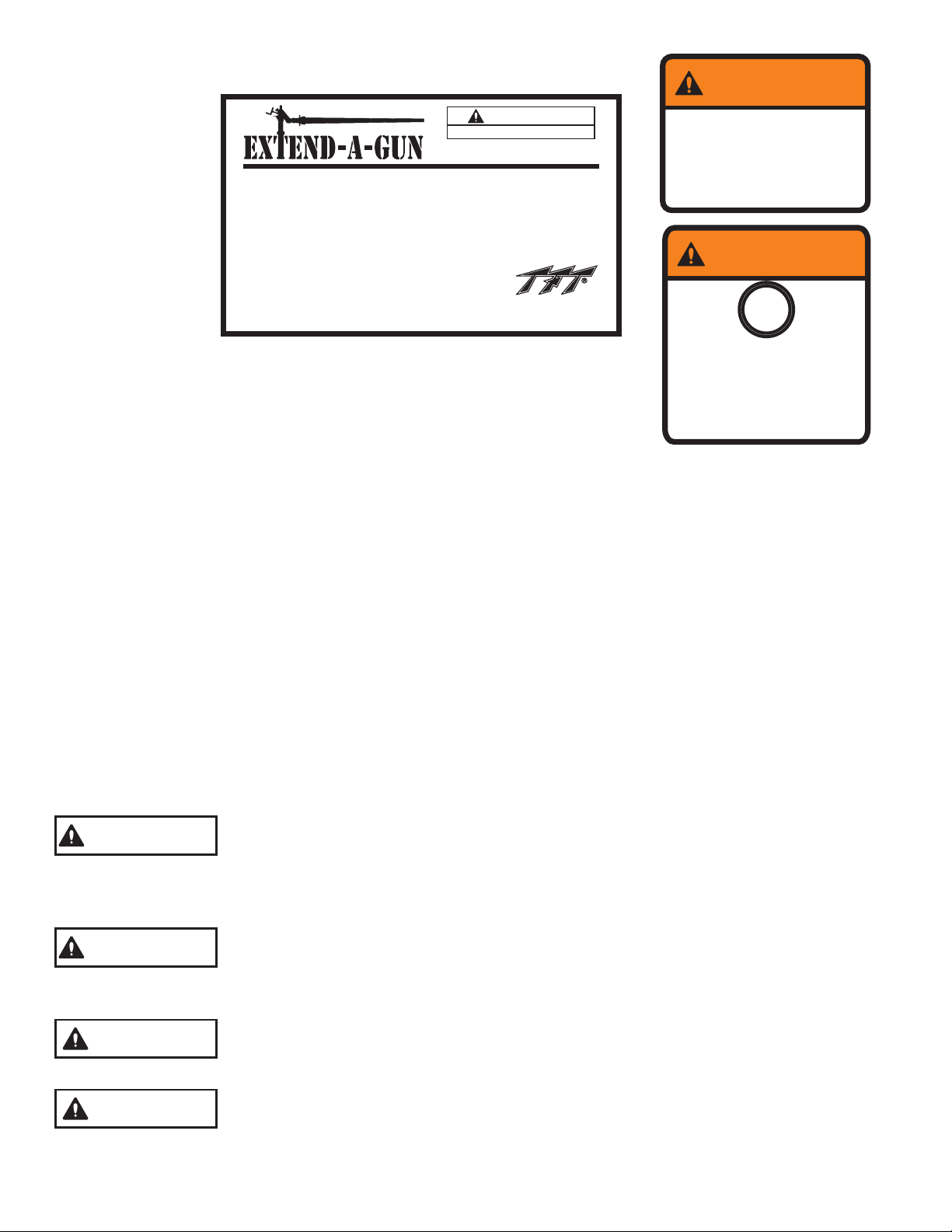
Attach the rectangular instruction label (XGL010) to a smooth flat surface where it can
be read by the person operating the Extend-a-Gun and monitor.
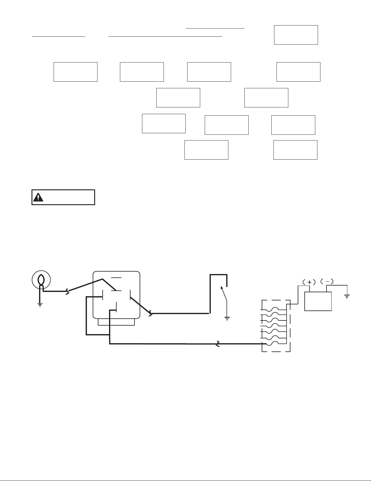
Attach the warning label (XGL020) next to the indicator light or warning label (XGL025)
around the indicator light on the truck dashboard.
INSTRUCTIONS
Support weight of monitor.
Lift slide bar to disengage latch.
Raise or lower monitor, with slide bar released,
until latch engages.
Check that slide bar is fully down and latches
are flush with housing.
1)
2)
3)
4)
TASK FORCE TIPS • 2800 East Evans Ave • Valparaiso, IN 46383-6940
+1 219 462-6161 • 800 348-2686 • www.tft.com • MADE IN U.S.A.
XGL010
Read manual before use.
WARNING When Light is ON,
Deck Monitor is
Lower Before
Moving Vehicle.
EXTENDED.
XGL020
WARNING
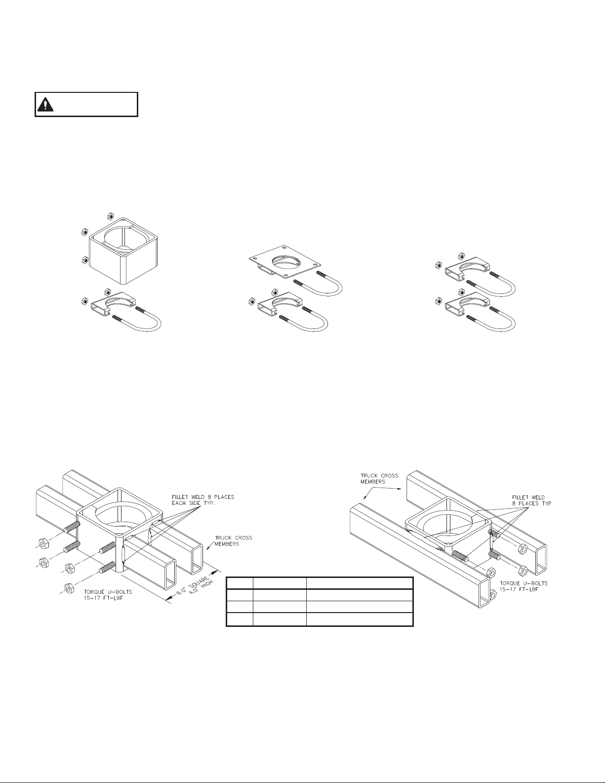
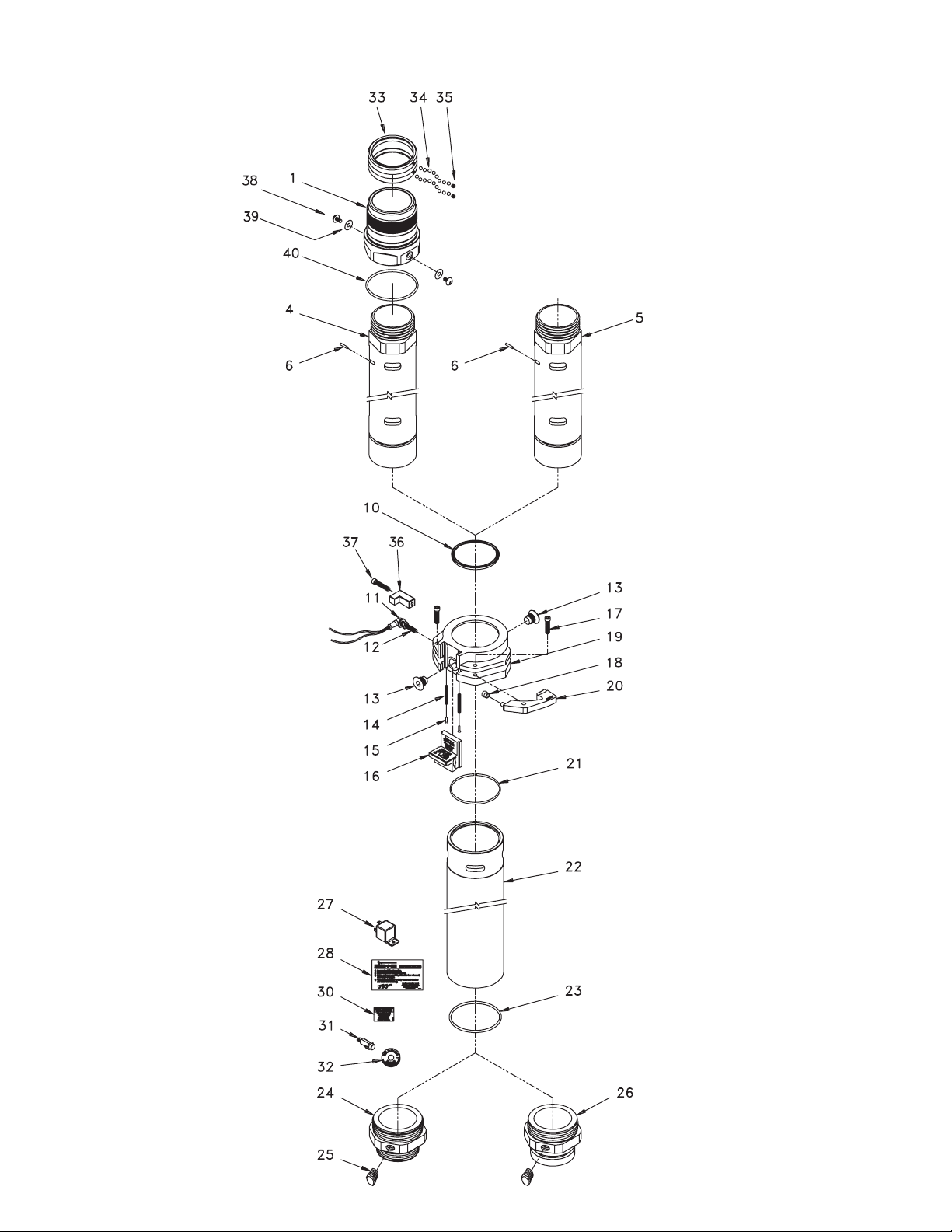
6.0 LABELS
7.0 MOUNTING MONITORS
8.0 OPERATING INSTRUCTIONS
XGL025
WARNING
When Light is ON,
Deck Monitor is
EXTENDED.
Lower Before
Moving Vehicle.
A Task Force Tips Crossfire® monitor may be mounted in one of two ways. We recommend that it be mounted directly on
Extend-A-Gun models XG12PL-XL, XG12VL-XL, XG18PL-XL, or XG18VL-XL, which have integral Crossfire bases built in.
Alternatively, it can be mounted on Extend-A-Gun models XG12PL- PL, XG12VL-PL, XG18PL-PL, or XG18VL-PL using
Task Force Tips part XFF-APL Truck Mount Base, which fits only the Task Force Tips Crossfire.
Akron Apollo® monitors may be mounted on Extend-A-Gun models XG12PL-PL, XG12VL-PL, XG18PL-PL, or XG18VL-PL
in one of two ways. We recommend that the direct mount flange be screwed directly to the 3" pipe threads on the Extend-
A-Gun. The base may be modified by having the flange turned down to 5" diameter at your local machine shop.
Alternatively, the direct mount flange can be bolted to Task Force Tips part XFF-CPL Companion Flange (or equivalent)
with out modification. Make sure that the flange bolts do not interfere with the Extend-A-Gun latch mechanism.
Elkhart Stinger® monitors must be bolted to Extend-A-Gun models XG12PL-PL, XG12VL-PL, XG18PL-PL, or XG18VL-PL
using Task Force Tips part XFF-CPL Companion Flange (or equivalent). Make sure the flange bolts do not interfere with
the Extend-A-Gun latch mechanism.
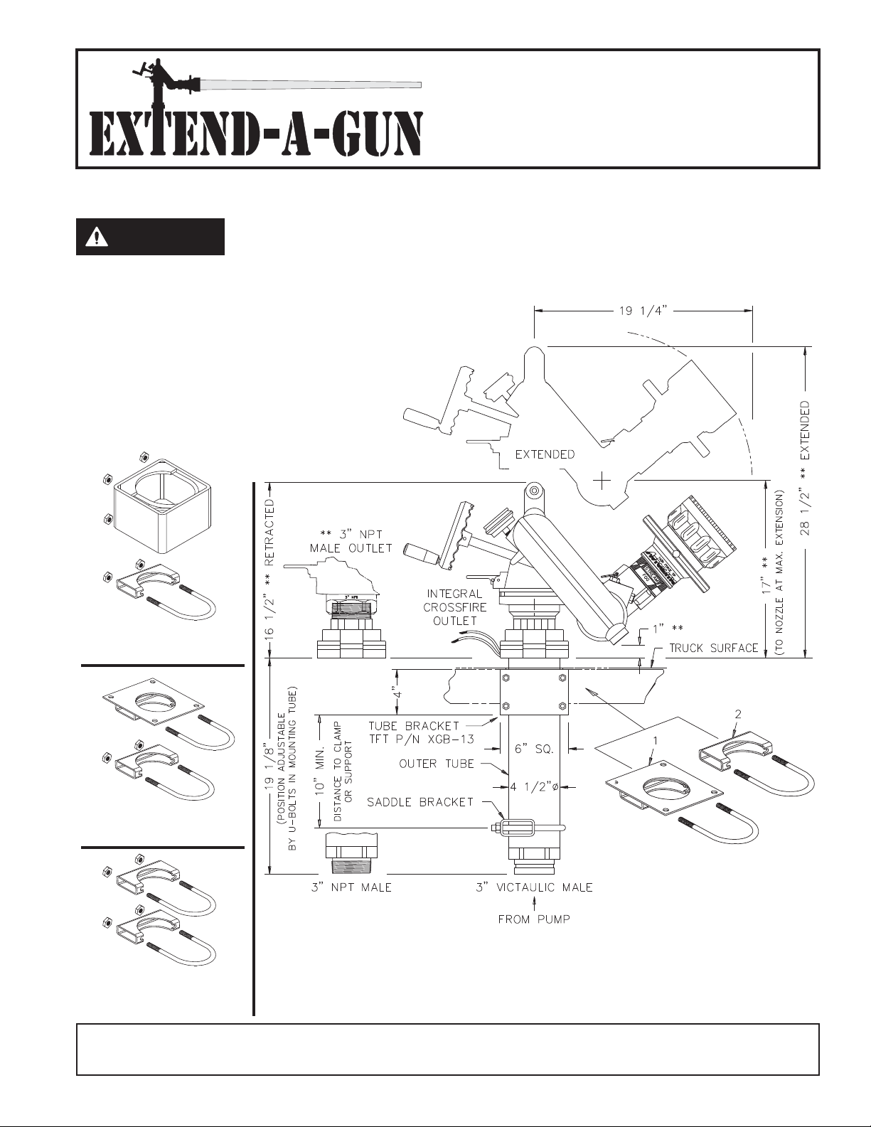
The Extend-A-Gun may be used in either the extended or retracted position,
but not in-between. Make sure the slide bar is down and both pawls are flush
with the housing before use. The word "UNLOCKED" located on the top of the
pawls should not be visible. When in use, the pawls are locked in position and
prevent the latch mechanism from operating.
Do not attempt to raise the Extend-A-Gun with water pressure. Rapid upward
movement of the Extend-A-Gun can cause injury to persons by striking them,
or knocking them off the fire truck. It can also cause damage to the Extend-A-
Gun, monitor, or other equipment.
Do not lift the slide bar when flowing water. The mechanism will not unlatch,
but the mechanism can be damaged.
Do not lift the slide bar to lower the deck gun with out supporting the weight
of the deck gun. It can fall and cause injury.
CAUTION
CAUTION
WARNING
WARNING
© Copyright Task Force Tips, Inc. 2002-2008