Task Force Tips HANDLINE User manual

©Copyright Task Force Tips, Inc. 2003 - 2010 LIH-020 September 25, 2010 Rev06
HANDLINE &
Maintenance and Service Procedure
For Nozzles with: Serial # TFT-H465101 and over
or Manufactured after 12/01/2003
INTRODUCTION
TASK FORCETIPSAUTOMATIC: The nozzle you have purchased is your primary
tool in the battle against fire. It has been manufactured with great care to give you
the finest performance possible. All components are of top quality and extremely
rugged. With regular inspection and attention it will serve you for many years.
This publication is intended for those who prefer to perform service on their own
equipment. Factory service is available and encouraged, and in most cases,
seldom exceeds 24 hours one day in our facility. Factory serviced equipment is
serviced by experienced workmen and fully tested before being returned. Repair
charges for non-warranty items are usually minimal and all serviced equipment is
promptly returned functioning to original specifications. Task Force Tips assumes
no liability, expressed or implied for damage to equipment or injury to personnel
that is a result of user service. IMPORTANT: After any maintenance or service,
always check nozzle for proper operation per INSPECTION CHECKLIST and flow
characteristics in “MANUAL: HAND-HELDAUTOMATIC NOZZLES” (LIN-030).
GENERAL INFORMATION
TOOLS REQUIRED
The following tools are required for general service to the nozzle:
3/32, 1/8, 7/32 and 5/16Allen wrenches
Dow #112 Lube/sealant
Loctite #271 thread locking adhesive
oxyacetylene torch
razor knife
Additional tools needed to service the shaper are:
strap wrench
vise with padded jaws
Handline / Dual-Force shaper removal clamp
(special tool TFT #THM-502)
Additional tools needed to service the pressure control are:
dental pick
two small probes, approximately 3/32 dia (such as a drill bit)
drill press, 17 inch opening
THREADEDJOINTS:havebeensecuredusingLoctite®#271threadlockingadhe-
sive.Disassemblyrequires a minimal applicationofheatwithanoxyacetylene torch
tobreakthe bond.Thethreads should beheatedtoapproximately450 F. Excessive
heatapplicationwillcausedamagetoadjacentseals andlabels. Replacementparts
must be reinstalled using Loctite® #271, or equivalent. Small vials of Loctite® #271
forfieldserviceare available; order Part # V5010, (Loctite® #271 - Mini Dispenser).
LUBRICANTS: If parts are disassembled in an area where O-rings are present,
reassemble using DOW #112 Lube on all O-rings and surfaces that the O-rings
contact. Call Dow Corning® Corp. at 800-447-4700 for the name of your nearest
distributor. The lube is also available through TFT as item number VSA-101. If the
nozzle is not disassembled refer to Field Lubrication Procedure Section (on back).
LABEL REPLACEMENT: If labels become damaged, remove old labels with a ra-
zor knife. Remove adhesive with acetone or methyl ethyl ketone. Surface must be
clean, dry and free from grease. Carefully apply new label.
ORDERING PARTS:Always specify the serial number of the nozzle when ordering
parts. The serial number is found on the back of the nozzle next to the coupling.
Be sure to use complete DESCRIPTION and ORDER #, as printed on parts list.All
requests for couplings must specify thread size. Pricing information will be given
at time of order. Parts and Repair Kits may be purchased on-line at www.tft.com
BACK END
COUPLINGAND BASE SERVICE PROCEDURE
TOOLS REQUIRED
1/8, 5/16Allen(hex) wrench
Loctite #271 thread locking adhesive
oxyacetylene torch
GENERAL: Occasional replacement of hose gaskets is recommended. Replace
GASKET GRABBER [13c or 3b] if severe impact has caused damage. Coupling
service kits which include all hardware and Loctite® #271 are available for all stan-
dard 1.5” or 2.5” couplings. Special configurations or model changes to a nozzle
can be made by selecting the desired coupling or base. Couplings with special
or standard threads are interchangeable and may be exchanged on new nozzles.
Please specify desired threads when ordering.
COUPLING AND BLITZ BASE REMOVAL: All couplings and blitz bases are re-
tained with a ball race and set screw. Heat and then remove the ¼”-28 SOCKET
SET SCREW [5c, or 1b] from the coupling using a 1/8”Allen wrench. Turn coupling
so that hole faces down and rotate coupling back and forth to allow 3/16” STAIN-
LESS STEEL BALLS [4b, 15c or 5b] to drop out. When all the balls are out of the
groove,thecoupling can be removed. Remove GASKET GRABBER/ debris screen
[13c, or 3b] from the coupling.
NOTE: On couplings [6c, 9c, 11c and 12c] and Base [2b], O-RING 141 [14c and
4b]willbefound adjacent to the GASKETGRABBER[13c, or 3b]. On coupling [2c],
O-RING 151 [3c] is used. Replace and grease the proper O-Ring before installing
the coupling.
COUPLING AND BLITZ BASE INSTALLATION: Insert the GASKET GRABBER/
debris screen [13c, or 3b] into the coupling, raised end pointing toward the front of
the nozzle. Put the coupling onto the mating part and load the correct number of
balls into the ball groove (SEE PARTS LIST ON EXPLODED VIEW OF NOZZLE
TO DETERMINE CORRECT NUMBER OF STAINLESS STEEL BALLS [4c, 15b
or 5b] FOR YOUR COUPLING). Insertion of the balls is easier if the coupling is ro-
tated slightly back and forth as the balls are loaded.Apply Loctite® #271 and install
proper¼”-28SOCKETSET SCREW [5c, or 1b].The set screw should be flush with
the surface of the coupling. If the coupling is difficult to turn, or feels rough when
turned,theset screw is in toofar.Backset screw offaturnor so and try again.Ifthe
feel is still not correct, recheck the number of balls in the coupling. On TIP ONLY
COUPLINGS and BLITZ BASES run the screw into the slot on the ball groove until
it bottoms out without applying pressure.
TIP ONLY BASE SERVICE: The TIP ONLY BASE [8b] is attached to the TIPONLY
BARRELASSEMBLY [7f ] by a threaded joint which is retained by Loctite® #271.
Apply heat to the knurled rib nearest the front of the nozzle. Damage to seals and
labelscanbereducedbyprotecting themwithawetcloth.TheTIPONLYBASE[8b]
can now be unscrewed. Remove and replace O-RING 143 [9b]. Clean all threads,
apply Loctite® #271 to threads and screw together.
TWIST TYPE VALVE SERVICE PROCEDURE
STO SLEEVE SERVICE:Toremove the STO SLEEVE [14b], first heatand remove
the CAM SCREWS [15b] and DETENT SCREWS [16b]. The detent screws contain
SPRINGS [18b] and BALLS [17b]. Then, STO SLEEVE [14b] can be slid off. Ser-
vice to interior STO valve should be done prior to reinstalling STO sleeve. Inspect
O-RINGS [19b] and replace if damaged. Installation is reverse of removal. Before
reassembly, grease O-Rings. Clean screw threads and apply Loctite® #271.
STO VALVE SERVICE: Heat the back end of the STO BASE [20b] with a torch and
unscrewthe STOTAILPIECE [11b].The STO SLIDER [13b] may nowbe removed.
Inspect and replace any damaged O-RINGS [9b, and 12b]. Grease O-Rings, clean
threadsand useLoctite®#271upon reassembly. Referto SLIDEVALVESERVICE
PROCEDURE for Valve Plug Replacement, Valve Shutoff Adjustment, and Valve
Adjustment for Severe Cold.
SLIDE VALVE SERVICE PROCEDURE
Tools Required:
3/32”Allen (hex) wrench
7/32”Allen (hex) wrench
5/16”Allen wrench Ball End
Flat Screw Driver
Mallet
DOW #112 Lube

©Copyright Task Force Tips, Inc. 2003 - 2010 LIH-020 September 25, 2010 Rev06
2
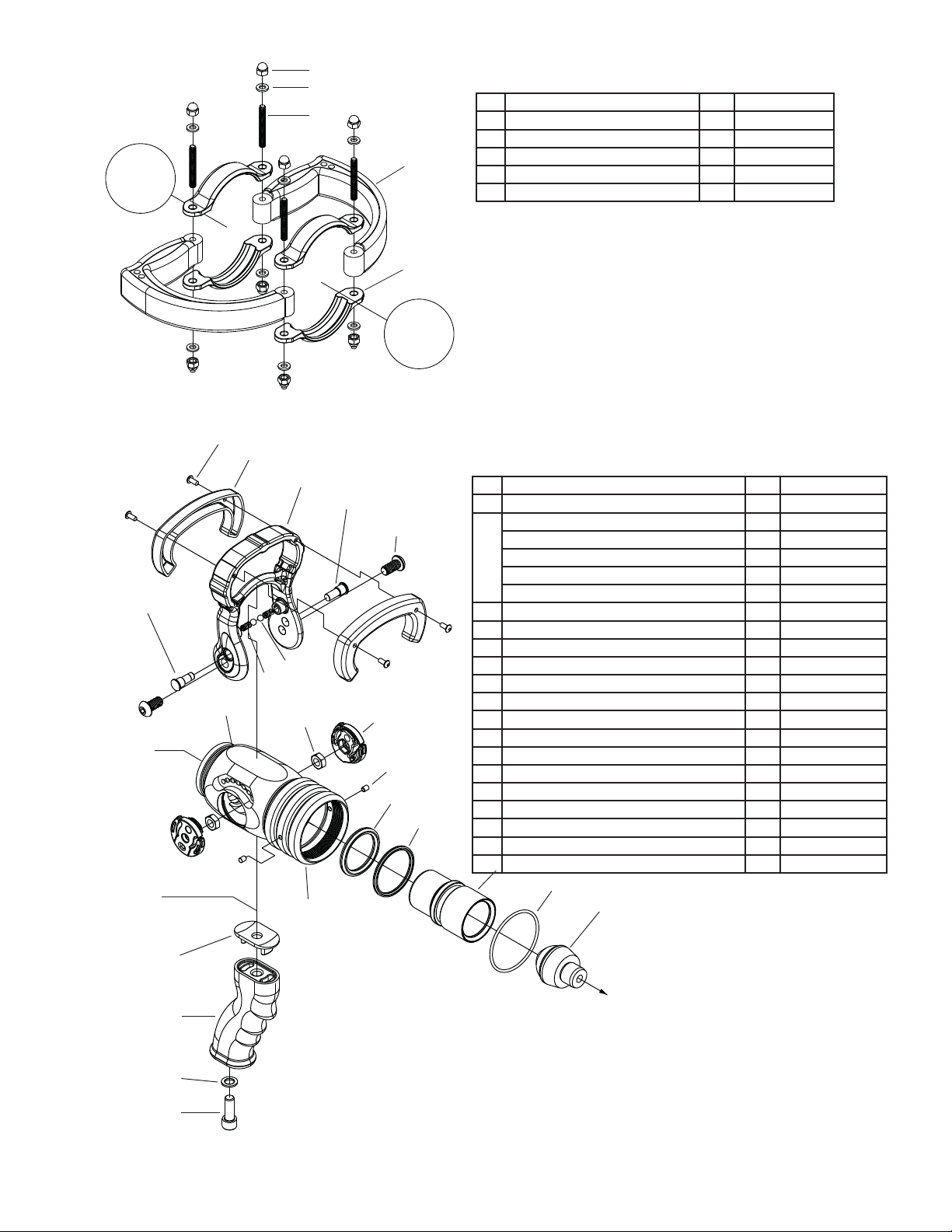
BOLT-ON PISTOL GRIP REMOVAL: PISTOLGRIP[19v]isheld on by a SOCKET
HEAD CAP SCREW [21v]. Remove screw with a 5/16” Ball DriverAllen wrench. To
reinstall, clean thread and apply Loctite® #271. Tighten screw to 95 in-lbs.
VALVE PLUG REPLACEMENT: Afterremoving back end, VALVE PLUG [17v,10b,
or 24b] is removed by pulling straight back. New valve plug can be installed using
a mallet.
VALVE SHUTOFF ADJUSTMENT: Shutoff valve is adjusted by the threads be-
tween the valve body and the front end of the nozzle. While holding the VALVE
HANDLE [3v]against stops intheOFF position, screwfrontendinto thevalvebody
until contact is made with the VALVE PLUG [17v]. Open handle to ON position to
remove contact. Screw the front end in 1/12 turn further to give the valve shutoff
compression. Thread in both SET SCREWS [12v] until they bottom out, without
applyingpressure.Inanalternatingfashioncontinueturninginsetscrewsuntil tight.
VALVE ADJUSTMENT FOR SEVERE COLD: To help prevent hose line freezing
in cold climates, the valve may be adjusted for intentional leakage by unscrewing
the front end slightly. The valve may then be returned to normal adjustment for
complete shut off during warm weather as stated above.
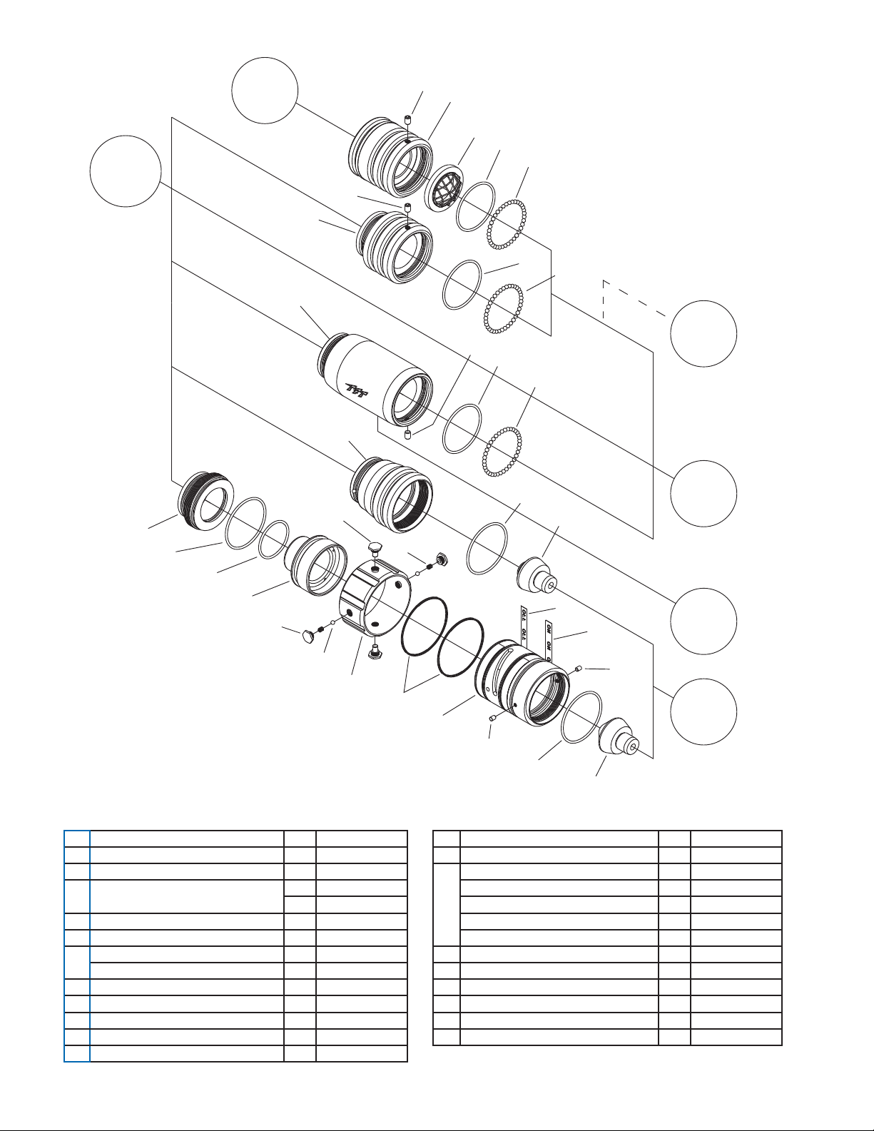
SLIDE VALVE DISASSEMBLY SEQUENCE
HANDLE REMOVAL: Remove both BUTTON HEAD CAP SCREWS [6v] from
VALVE HANDLE [3v] using a 7/32” Allen wrench. Slide CAM and SAFETY PINS
[4v and 5v] out of handle by gently prying about 3/8” apart the handle and the valve
body using a flat screw driver. To remove the handle, pull upwards while containing
theDETENTBALLS [7v] and SPRINGS [8v] toprevent their loss. Service to interior
valve parts should be done prior to reinstalling handle.
SLIDER AND SEAL REMOVAL: Remove #10-32 x ¼” SOCKET SET SCREWS
[12v] from the VALVE ASSEMBLY [11v] using a 3/32” Allen wrench. Unscrew front
portion of nozzle from valve. SLIDER [15v] can now be pulled out from the front of
valve. Remove and inspect O-RINGS [13v, 14v and 16v]. Replace O-Rings if they
are damaged.
SLIDE VALVE ASSEMBLY SEQUENCE
SLIDER AND SEAL INSTALLATION: Insert O-RINGS [13v, 14v and 16v] into
the proper grooves in the valve body. Check SLIDER [15v] for any raised metal at
groove area. Replace if necessary. Lubricate O-Rings and slider with DOW #112
Lube. Push slider into the valve body.
HANDLE INSTALLATION: Insert DETENT SPRINGS [8v] and DETENT BALLS
[7v] into the handle lugs. While holding balls in place, snap the HANDLE [3v] into
placewithoffsetholes FORWARD.Carefully align thegrooveonSLIDER[15v]with
offset hole in VALVE DISCS [9v] and with offset hole in handle. Slide SAFETYPIN
[5v] into offset hole in handle. Push down into engagement with groove in slider,
until head of pin is flush with handle. Repeat procedure for CAM PIN [4v]. Insert
BUTTON HEAD SCREWS [6v] through the lower handle holes. Thread each into
corresponding center trunnion hole. Tighten HANDLE SCREWS [6v] securely with
atorquevalueof100in-lbs(11.3N m). Handle should click firmlyand smoothly into
all detent positions and the slider should move back and forth smoothly. The force
to move handle should be between 5 lbs and 13 lbs applied at top center of handle.
FRONT END
SHELL SERVICE PROCEDURE
SHAPER REMOVAL: The rubber bumper is permanently bonded onto the stream
shaper as a single unit referred to as the SHAPER [10f]. The shaper is attached
to the SHAPER GUIDE [4f, or 5f] by a threaded joint that is retained by Loctite®
#271. Grip rear portion of the nozzle in a vise with padded jaws, or clamp SHAPER
GUIDE [4f, or 5f] using TFT special tool TH502 held in a vise. Direct a hot narrow
flamearound the rear portion ofthe shaper and heatfor approximately 20seconds.
Damage to BUMPER [10f] and LABELS [1f, 2f, or 6f] can be reduced by protecting
them with a wet cloth. Use a strap wrench to unscrew the shaper from the shaper
guide. Remove the shaper. Inside the shaper are (48) 13/16”ACETALBALLS [8f],
some of which may fall free as the Shaper is removed. If Shaper is to be reused,
clean ball track and replace 336 O-RING [9f] if damaged.
SERVICE TO CAM GROOVES AND BALLS: When Shaper is removed, check
to see if the stream shaping GUIDE BALLS [3f] and CAM GROOVES [7f - part of
BARRELCONE ASSEMBLY] are damaged. Replace Balls if sheared or missing. If
the CAM GROOVES are badly damaged, the BARREL CONE ASSEMBLY should
also be replaced.
BARREL CONE ASSEMBLY SERVICE: This assembly is permanent and cannot
be taken apart. Check to ensure that the flush spring is not damaged by pushing
down on the Barrel Cone with both hands (about 50 lbs force). The Barrel Cone
AssemblyshouldbereplacediftheBarrel Cone does not push down or spring back
up by itself. Lightly grease the CAM GROOVES before re-installing the SHAPER
GUIDE.
SHAPER INSTALLATION: Install 336 O-RING [9f] in front groove of SHAPER
[10f]. Grease the seal and ball groove heavily. Place (48) 13/16” ACETAL BALLS
[8f] into greased ball groove. Apply Loctite® #271 to male thread on SHAPER
GUIDE[4f, or5f].StartshaperontoSHAPERGUIDEthreads. PlacethreeSHAPER
GUIDE BALLS [3f] into the grooves on barrel and screw down shaper until threads
bottom out.
PRESSURE CONTROL SERVICE PROCEDURE
Tools Required:
1/4Allen wrench (10” Long)
1/4Allen wrench (regular length)
Mallet
PRESSURE CONTROL REPLACEMENT: The pressure control may be removed
and replaced as a unit by following the procedure in the PRESSURE CONTROL
REMOVALand INSTALLATION AND INITIALOPENINGADJUSTMENT sections.
NOTICE: The Pressure Control Unit is part of the BARREL ASSEMBLY [7f]. This
unitisfactorycalibratedandsealed.Serviceonthisunitisbestperformedatthefac-
tory using special tooling and equipment. In the unlikely event that this unit should
need service, it is highly recommended that you return the complete nozzle to the
factory for repairs OR replace the entire PRESSURE CONTROL UNIT. DO NOT
ATTEMPTTODISASSEMBLETHEPRESSURECONTROLUNIT!TaskForceTips
willassume NO liability for damage orinjury resulting fromattempts to disassemble
or repair the Pressure Control Unit.
PRESSURE CONTROL REMOVAL: To remove the CONTROLUNIT first separate
the front end from the nozzle, then remove the VALVE PLUG (106, 24b or 17v).
Loosen and remove the shaft locking SCREW (1p) with a 3/16 allen wrench. Insert
a 7/32Allen wrench into the front of the shaft and screw the shaft out of the barrel
assembly. LOCKING SLEEVE (2p) is removed by pushing it forward and out of
BARRELASSEMBLY (7f) with a punch. Note: LOCKING SLEEVE may require light
tapping with a hammer to remove.
PRESSURE CONTROL INSTALLATIONAND INITIAL OPENING ADJUSTMENT:
To install the CONTROL UNIT, lightly grease I.D. and O.D. of locking sleeve and
also threads of the screw. Place LOCKING SLEEVE (2p) with hollow end forward
onto back of shaft, thread finger tight. Note: If old LOCKING SLEEVE is reused it
may require light tapping with a hammer and punch to install. Screw CONTROL
UNIT (with pressure control parts installed) into barrel assembly. Insert a 7/32 Allen
wrench into front of shaft and turn in until baffle just touches BARREL CONE (7f)
then turn back between ½ and 3/4 of a turn (opening gap of .026/.036 inches or
.66/.91mm).KeepAllenwrench in shaft to assure that shaft doesn’t turn and tighten
screw against locking sleeve, to approximately 180 in-lbs.
IMPORTANT: Always flow test after adjusting. Nozzle pressure and flow require-
ments are shown on the following table:
INITIAL OPENING at 40 PSI (2.8 BAR)
FLOW (MIN) FLOW (MAX) Opening Gap (REF)
38 GPM 58 GPM .026/.036in
(144L/MIN) (204 L/MIN) (.66/.91mm)
NOZZLE PRESSURE NOZZLE PRESSURE
AT 95 GPM AT 250 GPM
100 PSI MODEL 85 PSI +/- 6 99 PSI +/- 6
75 PSI MODEL 60 PSI +/- 6 80 PSI +/- 6
DUAL-FORCE KNOB REMOVAL: To remove the DUAL-FORCE KNOB [8p] from
the BAFFLE [4p]:
1) Turn knob to standard setting.
2) Turn the SHAPER [10f] back to full flush.
3) Insert a small probe (such as a 1/16” drill bit) into the smaller of the two holes on
top of the knob.
4) Simultaneously push down with probe while turning knob clockwise (when
viewed from the front). Once knob turns a little, the probe may be removed.
5) Turn knob clockwise until it hits a stop. (about 25 degrees).
6) Pull knob to remove from baffle.

©Copyright Task Force Tips, Inc. 2003 - 2010 LIH-020 September 25, 2010 Rev06
3
DUAL-FORCE KNOB INSTALLATION:
1) Place the label (HXD752) into the knob (HXD560).
2)Add o-ring (VO-005) to o-ring groove on top of the baffle (HXD561) and groove.
3) Place the knob onto the Baffle fully.
4) Install the Compression Spring (VM4195) and Torlon Ball (VB156TO).
5) Push down on Compression Spring and Torlon Ball and twist the Knob counter-
clockwise till it clicks in place.
6) Check for smooth operation between standard and low pressure settings.
PROBLEMS:
If you have any questions or problems, please call for assistance.
(800) 348-2686 • (219) 462-6161 • FAX (219) 464-0620
TASK FORCE TIPS INC. - www.tft.com
3701 Innovation Way • Valparaiso, IN 46383-9327
HXD752 Label
FIGURE 1 HXD560 Knob
FIGURE 2
STANDARD
36,
LOW
35(6685(
LOW
35(6685(
STANDARD
36,
EXPLODED VIEWS and PARTS LISTS
To ALL BASE and
SLIDE VALVE PARTS
(except 2-1/2 Blitz Base)
2-1/2"
ROCKER LUG
BRITISH
INSTANTAEOUS
STORZ
1-1/2" FULL-TIME
ROCKER LUG
2-1/2" LOCKOUT
ROCKER LUG
To 2-1/2
BLITZ BASE
ONLY
1c 5c
2c
3c
4c
5c
6c
7c
9c
5c
8c
15c
11c
5c
14c
13c
10c
1c
5c
12c
INDEX DESCRIPTION QTY PART #
1c 2.5" HOSE GASKET 1 V3190
2c 2.5" ROCKER LUG COUPLING 1 P197
3c O-RING-151 1 VO-151
4c 3/16 SS BALLS 48 V2120
5c 1/4-28X3/8 SOCKET SET 1 VT25-28SS250
6c 2.5" BIC COUPLING 1 H687
7c 52 MM STORZ COUPLING 1 H686
8c O-RING-134 1 VO-134
9c 2.0" BSP MALE SWIVEL 1 H685
10c 1.5" COUPLING GASKET 1 V3130
11c 1.5" ROCKER LUG COUPLING 1 H694
12c 2.5" ROCKER LUG COUPLING 1 P198
13c 1.5" HARD GASKET GRABBER
SINGLE 1 H730-60D
DUAL FORCE 1 HD730-60D
14c O-RING-141 1 VO-141
15c 3/16 SS BALLS 38 V2120

©Copyright Task Force Tips, Inc. 2003 - 2010 LIH-020 September 25, 2010 Rev06
4
From ALL
COUPLINGS
(except 2-1/2
ROCKER LUG)
OPTIONAL
PLAYPIPE
PARTS
To
SLIDE
VALVE
PARTS
To
PISTOL GRIP
PART SET
(see Slide
Valve Parts)
To
FRONT
END
SHELL
From 2-1/2
ROCKER LUG
1b
2b
3b
4b
5b
4b
5b
4b
5b
6b
1b
7b
1b
9b
10b
18b
8b
12b
9b
11b
17b
16b
13b
14b
15b
23b
20b
19b
24b
9b
23b
22b
21b
2.5” BLITZ
1.5” BLITZ
MODEL VPG
MODEL T.O.
MODEL S.T.O.
BASES, TIP ONLY and TWIST TYPE
# DESCRIPTION QTY PART #
1b 1/4-28 X 3/8 SOCKET SET SCREW 1 VT25-28SS375
2b 2.5" BLITZ BASE 1 H675
3b 1.5" HARD GASKET GRABBER 1 H730-60D
1 HD730-60D
4b O-RING-141 1 VO-141
5b 3/16 SS BALLS 37 V2120
6b 1.5" BLITZ BASE 1 H674
7b PISTOL GRIP BODY - LONG 1 H692
8b TIP ONLY BASE 1 H670
9b O-RING-143 2 VO-143
10b TIP ONLY PLUG 1 HX591
11b TAIL PIECE - STO 1 HD662
12b O-RING-132 1 VO-132
# DESCRIPTION QTY PART#
13b SLIDER - STO 1 HD660
14b SLEEVE - STO 1 HD668
15b CAM SCREW 2 HD780
16b DETENT SCREW 2 HD785
17b 3/16" TORLON BALL 2 V2120-TORLON
18b DETENT SPRING - STO 2 VM4200
19b QUAD-RING-039 2 VOQ-4039
20b BASE - STO 1 HD665
21b OFF LABEL - RED 1 HD755
22b ON LABEL - BLUE 1 HD750
23b 10-32 X 1/4 SET SCREW-ND PATCH 2 VT10Y32SS250
24b VALVE PLUG - STO 1 HXD591

©Copyright Task Force Tips, Inc. 2003 - 2010 LIH-020 September 25, 2010 Rev06
To
SLIDE
VALVE
PARTS
From
BLITZ
BASES
1h
4h
3h
2h
5h
PLAYPIPE HANDLE
# DESCRIPTION QTY PART#
1h 1/4-20 SS ACORN NUT 8 VT25E20AC
2h WASHER 8 VW500X265-63
3h 1/4-20 X 2 STUD FULL THREAD 4 VT25-20ST2.0
4h PLAYPIPE HANDLE 2 P220
5h BLITZ BRACKET 4 H676
To
LONG
GRIP
(VPG)
From
COUPLINGS
BASES
To
FRONT
END
SHELL
8v
6v
4v
3v
2v
1v
7v
10v 9v
16v
15v
14v
13v
12v
17v
11v
18v
19v
20v
21v
SERIAL NUMBER
5v
SLIDE VALVE
# DESCRIPTION QTY PART#
1v 8-32 X 3/8 BH CAP SCREW 4 VT08-E32BH375
2v VALVE HANDLE COVER 2 HM625-BLK
3v VALVE HANDLE 1 HX620
4v CAM PIN 1 HX630
5v SAFETY PIN 1 HX635
6v 3/8-24 X 3/4 BUTTON HEAD SCREW 2 VT37E24BH750
7v DETENT BALL 2 VB243TO
8v DETENT SPRING 2 HM770
9v DISC 2 HX640
10v 3/8-24 HEX JAM NUT 2 VT37-24JNT
11v VALVE BODY 1 HX600
12v 10-32 X 1/4 SET SCREW-ND PATCH 2 VT10Y32SS250
13v QUAD-RING 326 1 VOQ-4326
14v QUAD-RING 225 1 VOQ-4225
15v SLIDER 1 H660
16v O-RING 143 1 VO-143
17v VALVE PLUG 1 HX590
18v GRIP SPACER 1 HM693-H
19v PISTOL GRIP - BLACK 1 HM692-BLK
20v WASHER 1 VM4901
21v 3/8-16 X 1" SOCKET HEAD CAP SCREW 1 VT37-16SH1.0

©Copyright Task Force Tips, Inc. 2003 - 2010 LIH-020 September 25, 2010 Rev06
For
SINGLE
PRESSURE
HANDLINE
1p
2p
4p
3p
5p
For
DUAL-FORCE
6p
7p 8p
10p
From
FRONT
END
SHELL
From
SLIDE VALVE
T.O. and
S.T.O.
To
PRESSURE
CONTROL
PARTS
3f
2f
4f
7f 8f
9f
10f
6f
9p
SHELL FRONT END
# DESCRIPTION QTY PART#
2f NAME LABEL HANDLINE - 100 PSI 1 HX745
NAME LABEL HANDLINE - 75 PSI 1 HX745L
NAME LABEL DUAL-FORCE 100/55 PSI 1 HXD745
NAME LABEL DUAL-FORCE 75/45 PSI 1 HXD745L
3f GUIDE BALLS 3 VB344TO
4f SHAPER GUIDE 1 HXD510
6f BARREL LABEL - SINGLE PRESS 1 H740
DUAL-FORCE 1 HD740
7f BARRELASSEMBLY - HANDLINE 1 HX850-KIT
8f 3/16" BALLS 48 V2115
9f O-RING 336 1 VO-336
10f SHAPER WITH BUMPER 1 H500
PRESSURE CONTROL
# DESCRIPTION QTY PART#
1p 5/16-18 X 3/4 SOCKET HEAD CAP SCREW 1 VT31-18SH750
2p LOCKING SLEEVE 1 HX571
3p PRESSURE CONTROLASSEMBLY
HANDLINE 100 PSI 1 HX840-KIT
HANDLINE 75 PSI 1 HX840-75-KIT
4p PRESSURE CONTROLASSEMBLY
DUAL FORCE 100/55 PSI 1 HXD840-KIT
DUAL-FORCE 75/45 PSI 1 HXDL840-KIT
5p O-RING 005 2 VO-005
6p SPRING 1 VM4195
7p 5/32” TORLON BALL 1 VB156TO
8p KNOB LABEL - 100 PSI STANDARD 1 HXD752
KNOB LABEL - 75 PSI STANDARD/LOW 1 HXD752L
9p KNOB 1 HXD560
10p DOME PLUG 1 VM4124

©Copyright Task Force Tips, Inc. 2003 - 2010 LIH-020 September 25, 2010 Rev06
DANGER
PERSONAL RESPONSIBILITY CODE
The member companies of FEMSA that provide emergency response
equipment and services want responders to know and understand the
following:
1. Firefighting and Emergency Response are inherently dangerous activities
requiring proper training in their hazards and the use of extreme caution
at all times.
2. It is your responsibility to read and understand any user’s instructions,
including purpose and limitations, provided with any piece of equipment
you may be called upon to use.
3. It is your responsibility to know that you have been properly trained in
Firefighting and /or Emergency Response and in the use, precautions, and
care of any equipment you may be called upon to use.
4. It is your responsibility to be in proper physical condition and to maintain
the personal skill level required to operate any equipment you may be
called upon to use.
5. It is your responsibility to know that your equipment is in operable
condition and has been maintained in accordance with the manufacturer’s
instructions.
6. Failure to follow these guidelines may result in death, burns or other
severe injury.
FEMSA
Fire and Emergency Manufacturers and Service Association
P.O. Box 147, Lynnfield, MA 01940 • www.FEMSA.org

©Copyright Task Force Tips, Inc. 2003 - 2010 LIH-020 September 25, 2010 Rev06
TASK FORCE TIPS, INC.
MADE IN USA • www.tft.com 3701 Innovation Way, Valparaiso, IN 46383-9327 USA
800-348-2686 • 219- 462-6161 • Fax 219-464-7155
WARRANTY
Task Force Tips, Inc., 3701 Innovation Way, Valparaiso, Indiana 46383-9327 (“TFT”) warrants to the original purchaser of its Ultimatic,
Mid-Matic, and Handline series nozzles (“equipment”), and to anyone to whom it is transferred, that the equipment shall be free from
defects in material and workmanship during the five (5) year period from the date of purchase.
TFT’s obligation under this warranty is specifically limited to replacing or repairing the equipment (or its parts) which are shown by
TFT’s examination to be in a defective condition attributable to TFT. To qualify for this limited warranty, the claimant must return the
equipment to TFT, at3701 Innovation Way, Valparaiso, Indiana 46383-9327, within a reasonable time after discovery of the defect.
TFT will examine the equipment. If TFT determines that there is a defect attributable to it, TFT will correct the problem within a
reasonable time. If the equipment is covered by this limited warranty, TFT will assume the expenses of repair.
If any defect attributable to TFT under this limited warranty cannot be reasonably cured by repair or replacement, TFT may elect to
refund the purchase price of the equipment, less reasonable depreciation, in complete discharge of its obligations under this limited
warranty. If TFT makes this election, claimant shall return the equipment to TFT free and clear of any liens and encumbrances.
This is a limited warranty. The original purchaser of the equipment, any person to whom it is transferred, and any person who is
an intended or unintended beneficiary of the equipment, shall not be entitled to recover from TFT any consequential or incidental
damages for injury to person and/or property resulting from any defective equipment manufactured or assembled by TFT. It is agreed
and understood that the price stated for the equipment is in part consideration for limiting TFT’s liability. Some states do not allow the
exclusion or limitation of incidental or consequential damages, so the above may not apply to you.
TFT shall have no obligation under this limited warranty if the equipment is, or has been, misused or neglected (including failure to
provide reasonable maintenance) or if there have been accidents to the equipment or if it has been repaired or altered by someone
else.
THIS IS A LIMITED EXPRESS WARRANTY ONLY. TFT EXPRESSLY DISCLAIMS WITH RESPECT TO THE EQUIPMENT
ALL IMPLIED WARRANTIES OF MERCHANTABILITY AND ALL IMPLIED WARRANTIES OF FITNESS FOR A PARTICULAR
PURPOSE. THERE IS NO WARRANTY OF ANY NATURE MADE BY TFT BEYOND THAT STATED IN THIS DOCUMENT.
This limited warranty gives you specific legal rights, and you may also have other rights which vary from state to state.
ANSWERS TO YOUR QUESTIONS
We appreciate the opportunity of serving you and making your job easier. If you have any problems or questions, our toll-free
“Hydraulics Hotline”, 800-348-2686, is normally available to you 24 hours a day, 7 days a week.
Visit www.tft.com. Go to Literature, Service Procedures and then
Service Poster to view a full-size version of this booklet.
This manual suits for next models
2
Table of contents
Other Task Force Tips Industrial Equipment manuals