TASKING iSYSTEM Infineon SGBT HSTCU User manual

Infineon SGBT (HSTCU) Active Probe
User Manual
V2.4, June 2023
isystem.com/start

General safety instructions
Please read the following safety precautions carefully before putting this device to use to avoid
any personal injuries, damage to the instrument, or to the target system. Use this instrument
only for its intended purpose as specified by this manual to prevent potential hazards.
Use included power cord and power supply
The enclosed power supply has been approved for use by iSYSTEM. Please contact iSYSTEM if
you need to consider an alternative power.
Use grounding wire
Prior to applying power to either the BlueBox or the target, connect the device and the target
system together with the included grounding wire. This is to avoid potential damage caused by
any voltage difference between the device and the target system.
Use proper overvoltage protection
Ensure proper protection to avoid exposing the BlueBox device or the operator to overvoltage
surges (e.g. caused by thunderstorm, mains power).
Do not operate without cover
Do not operate the device with cover removed.
Avoid circuit and wire exposure
Do not touch exposed components or wires when the device is powered.
Do not operate with suspected damage
If you suspect damage may have occurred, the BlueBox device must be inspected by qualified
service personnel before further operation.
Do not operate the device outside its rated supply voltage or environmental range
Consult with iSYSTEM before using equipment outside of the parameters provided in this
manual.
This symbol is used within the manual to highlight further safety notices.

Contents
Package content ................................................................................................................................ 4
Specifications ....................................................................................................................................... 5
Operation ............................................................................................................................................... 6
mDIO Cable ................................................................................................................................................ 8
HSTCU (USB-C) to Samtec22 Converter .............................................................................................. 9
HSTCU (USB-C) to DAP10 1.27 Converter ......................................................................................... 11
Hardware Setup and Configuration ..................................................................................... 13
Accessories ......................................................................................................................................... 14
User Notes .......................................................................................................................................... 15

Package content
Infineon SGBT (HSTCU) Active Probe enables debugging, tracing and testing of all Infineon
AURIXT™ TC2xx, TC3xx (2nd generation), TC4xx (3rd generation) microcontrollers. It supports the
DAP and Aurora GigaBit Trace (AGBT/SGBT) interface via USB-C connector. Its small and compact
hardware size allows for connecting to a target microcontroller in a confined space as far as 10 m
away. The Active Probe supports up to 1 parallel AGBT lanes, running at a maximum bitrate of
5Gbps.
The Infineon SGBT (HSTCU) Active Probe kit is delivered with the following components:
Infineon SGBT (HSTCU)
Active Probe
1m FNet Cable
Ordering code:
IC57166
Ordering code:
BB-FNET-100

Specifications
GENERAL
Supply voltage
9.0V DC via FNet cable
Operating temperature
10°C to 40°C
Storage temperature
-10°C to 60°C
Humidity
5% to 80% RH
MECHANICAL
Size
80 x 55 x 18 mm
Weight
0.125 kg
OPERATION
Communication
interface to BlueBox
iSYSTEM proprietary FNet
Debug signal valid input
voltage range
5.0V (max. 5.5V)
Power consumption
Max. 1.5W (dependent on operation mode)
Number of supported
AGBT lanes
1 lane
Maximum AGBT bitrate
5Gbps
AGBT clock source
options
Active Probe
PROTECTION
Debug signals
33 Ohm series termination/protection resistors, ESD protection devices
DAP1-3 and DAPE1-3
10k Ohm pull-down
DAP_RESET
1k Ohm pull-up, 33 series termination/protection resistor
VREF
1k Ohm input impedance
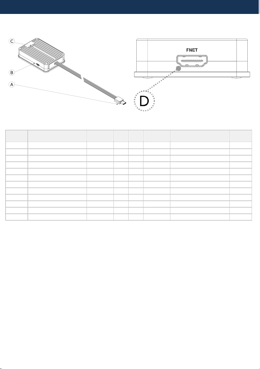
Operation
A– USB-C connector, with the following pinout:
Signal
Direction
Signal Description
Signal
Pin
Pin
Signal
Signal Description
Signal
Direction
Ground
GND
A1
B12
NC
Not Connected
I
AGBT TX0_P
TX0+
A2
B11
CLK+
AGBT Clock
O
I
AGBT TX0_N
TX0-
A3
B10
CLK-
AGBT Clock
O
Not Connected
NC
A4
B9
NC
Not Connected
I/O
Target Reset Pin
nRESET
A5
B8
DAP1
DAP Data
I
I/O
Optional 2nd DAP data
DAP2
A6
B7
nTRST
Output
O
I/O
Optional 3rd DAP data
DAP3
A7
B6
NC
Not Connected
O
DAP Clock
DAP0
A8
B5
Vref
Reference Voltage
I
Not Connected
NC
A9
B4
NC
Not Connected
Not Connected
NC
A10
B3
NC
Not Connected
Not Connected
NC
A11
B2
NC
Not Connected
Ground
GND
A12
B1
GND
Ground
(HSTCU) USB-C pinout
Blue colored signals are trace signals.
Signal direction definition:
O – Output from the Active Probe to the target microcontroller
I – Input to the Active Probe from the target microcontroller

B – mDIO port marked as TRIG on the housing
mDIO port provides two digital signals, which can interact with the embedded target. Each can be
configured either for input or output operation.
Number
Name
Pin1
IOØ
Pin2
IO1
Pin3
GND
mDIO port pinout
mDIO port on the Active Probe
C – The indicator light provides the status of the Active Probe as follows:
Permanently green – Powered on and ready to use.
Blinking green – Establishing connection with the BlueBox.
Blinking blue – Reprogramming SPLASH.
Permanently magenta – Golden image loaded and ready to use.
D – FNet connector, that connects the Active Probe to the iC5700 BlueBox. The FNet cable is
delivered with the Active Probe.
When powering on the system, switch the iC5700 on before powering on the target. When
powering down the system, power off the target before powering off the iC5700!
Use only original iSYSTEM accessories for powering and connecting with the iC5700. Consult
with iSYSTEM before attempting to use any other accessory.
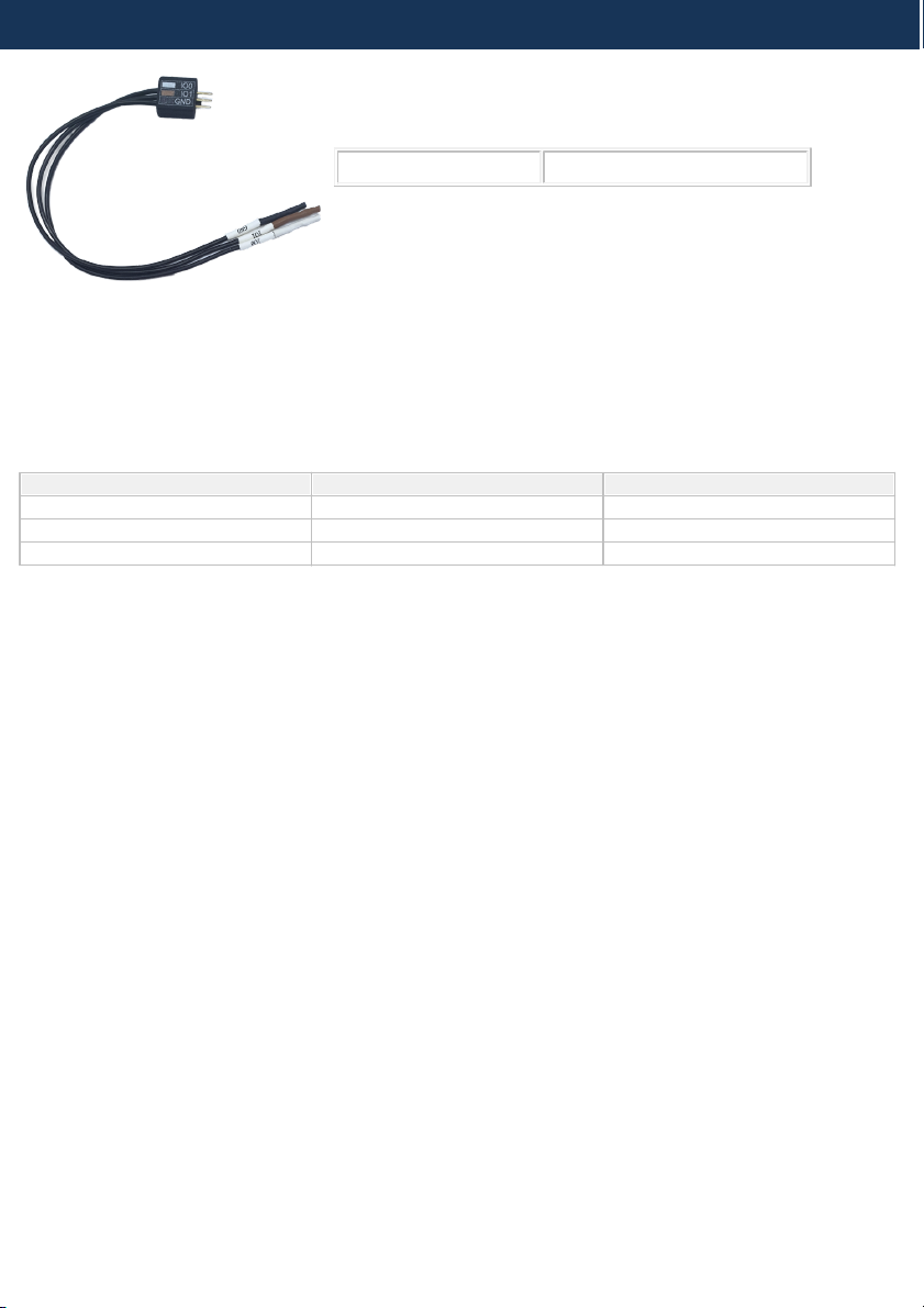
mDIO Cable
Ordering code
BB-AP-MDIO-20
mDIO Cable is used to connect the Active Probe mDIO port with the signals around the debugged
microcontroller, which can then be either read or controlled by the debugger. For example, the
debugger can periodically service an external watchdog through the mDIO output or just read and
record an external signal through the mDIO input. It must be ordered separately. Length of the cable
is 20 cm.
The following pinout is valid on the Active Probe side:
Number
Name
Color
Pin1
IOØ
White
Pin2
IO1
Brown
Pin3
GND
Black
mDIO Cable pinout

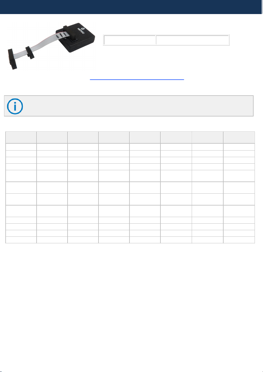
HSTCU (USB-C) to Samtec22 Converter
Ordering code
IAHSTCU-SAM22
The converter is used to connect the Infineon SGBT (HSTCU) Active Probe with the USB-C connector
to a target featuring Samtec 22-pin ERF8 debug connector. The 22-pin converter must be ordered
separately.
Connecting USB-C converter to the Active Probe
Used physical USB-C type connector doesn’t feature the USB interface as someone could presume
(there is no way to incorrectly insert it), but rather the Infineon AGBT (Aurora GigaBit Trace) interface
whose signals are connected to the connector in a way that USB-C connector orientation matters.
When attaching this converter to the Active Probe, make sure its marking A and marking B is
aligned and matches with the markings on the Active Probe connector.

The following pinout is valid on the converter side:
Signal
Direction
Signal Description
Signal
Pin
Pin
Signal
Signal Description
Signal
Direction
Ground
GND
A1
B12
NC
Not Connected
I
AGBT TX0_P
TX0+
A2
B11
CLK+
AGBT Clock
O
I
AGBT TX0_N
TX0-
A3
B10
CLK-
AGBT Clock
O
Not Connected
NC
A4
B9
NC
Not Connected
I/O
Target Reset Pin
nRESET
A5
B8
DAP1
DAP Data
I
I/O
Optional 2nd DAP data
DAP2
A6
B7
nTRST
Output
O
I/O
Optional 3rd DAP data
DAP3
A7
B6
NC
Not Connected
O
DAP Clock
DAP0
A8
B5
Vref
Reference Voltage
I
Not Connected
NC
A9
B4
NC
Not Connected
Not Connected
NC
A10
B3
NC
Not Connected
Not Connected
NC
A11
B2
NC
Not Connected
Ground
GND
A12
B1
GND
Ground
(HSTCU) USB-C pinout
Blue colored signals are trace signals.
The following pinout is valid on the target side:
Signal Direction
Signal
Description
Signal
Pin
Pin
Signal
Signal
Description
Signal Direction
I
AGBT TX0_P
TX0+
1
2
Vref
Reference
Voltage
I
I
AGBT TX0_N
TX0-
3
4
DAP0
DAP Clock
O
Ground
GND
5
6
DAP1
DAP Data
IO
Not Connected
NC
7
8
NC
Not Connected
Not Connected
NC
9
10
DAP2
Optional 2nd
DAP data
I
Ground
GND
11
12
nTRST/DAPEN
Output
O
Not Connected
NC
13
14
CLK+
AGBT Clock
O
Not Connected
NC
15
16
CLK-
AGBT Clock
O
Ground
GND
17
18
TGO
AGBT Trigger
out
I
Not Connected
NC
19
20
NC
Not Connected
Not Connected
NC
21
22
nRESET
Reset
IO
Revision A2: Samtec 22-pin ERF8 pinout
Blue colored signals are trace signals.
*Current TriCore devices feature only one AGBT line while the Active Probe hardware is ready for
future devices with more AGBT lines.
HSTCU (USB-C) to DAP10 1.27 Converter
Ordering code
IAHSTCU-DAP10
This converter is used to connect Infineon SGBT (HSTCU) Active Probe (Ordering code: IC57166) to
the target via DAP connector. It must be ordered separately.
When attaching this converter to the Active Probe, make sure its marking A and marking B is
aligned and matches with the markings on the Active Probe connector.
The following pinout is valid on the converter side:
Signal Direction
Signal
Description
Signal
Pin
Pin
Signal
Signal
Description
Signal Direction
Ground
GND
A1
B12
NC
Not Connected
Not Connected
NC
A2
B11
NC
Not Connected
Not Connected
NC
A3
B10
NC
Not Connected
Not Connected
NC
A4
B9
NC
Not Connected
I/O
Target Reset
Pin
nRESET
A5
B8
DAP1
DAP Data
I
I/O
Optional 2nd
DAP data
DAP2
A6
B7
NC
Not Connected
I/O
Optional 3rd
DAP data
DAP3
A7
B6
NC
Not Connected
O
DAP Clock
DAP0
A8
B5
Vref
Reference
Voltage
I
Not Connected
NC
A9
B4
NC
Not Connected
Not Connected
NC
A10
B3
NC
Not Connected
Not Connected
NC
A11
B2
NC
Not Connected
Ground
GND
A12
B1
GND
Ground
(HSTCU) USB-C pinout
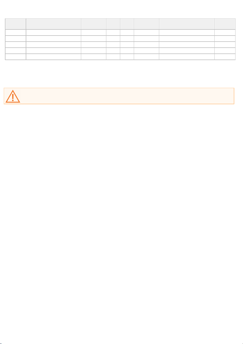
The following pinout is valid on the target side:
Signal
Direction
Signal Description
Signal
Pin
Pin
Signal
Signal Description
Signal
Direction
I
Reference Voltage
Vref
1
2
DAP1
DAP Data pin
I/O
Ground
GND
3
4
DAP0
DAP clock
O
Ground
GND
5
6
DAP2
Optional 2nd DAP Data pin
I/O
Not Connected
NC
7
8
DAP3
Optional 3rd DAP Data pin
I/O
Ground
GND
9
10
nRESET
Reset
I/O
10-pin Infineon DAP pinout
Signal Direction is described from the BlueBox perspective.
When connecting the BlueBox to a target for the first time, double check that the debug
adapter pinout matches the Target connector. A mismatch can result in a hardware failure.

Hardware Setup and Configuration
For detailed visual presentation of the hardware setup and configuration, refer to Getting
started tutorial. Use short link isystem.com/start.
1. Connect the power supply cable. BlueBox should be switched off.
2. First connect via USB. Later you can configure TCP/IP connection to work remotely.
3. Connect the Grounding wire to the BlueBox and the Target.
If the Grounding wire is not connected, the ground potential difference between the BlueBox
and the Target can exceed well over 1000V even before any of the devices are powered up.
This voltage difference is discharged over the BlueBox and the Target, leading to the
possible destruction of electronic components.
4. Connect FNet cable of Active Probe to the BlueBlux FNet port.
Although it looks similar to the HDMI interface, the FNet Port is not compatible with HDMI
or any HDMI accessories.
Connecting iSYSTEM hardware to HDMI accessories will damage the hardware and will
render the iSYSTEM hardware warranty void.
5. Power ON the hardware in the following order:
a. BlueBox
b. Target
6. Install winIDEA and create a new workspace.
7. Configure Debug channel modes via Hardware / CPU Options / SoC.
For troubleshooting refer to Knowledge Base - kb.isystem.com.
More general settings are described in winIDEA Help.
Accessories
Infineon USC-B Active Probe Accessories
Description
Ordering Code
USB-C to Samtec 22-pin TriCore Adapter
IAHSTCU-SAM22
1.0m FNet Cable
BB-FNET-100
3.0m FNet Cable
BB-FNET-300
5.0m FNet Cable
BB-FNET-500
mDIO Cable
BB-AP-MDIO-20
The functionality can be extended through the use of various modules from IOM6 product line
which enable capabilities from parallel debugging of multiple targets, monitoring of network traffic
and monitoring and manipulation of analog and digital signals.
More information about our products on www.isystem.com or via sales@isystem.com.

User Notes
This page is intentionally left blank.

www.isystem.com
Visit our website for:
·
Support - isystem.com/support
·
Tutorials - isystem.com/getting-started
·
Knowledge Base - kb.isystem.com
This manual suits for next models
2
Table of contents
Other TASKING Measuring Instrument manuals

TASKING
TASKING iSYSTEM Infineon DAP/DAPE II User manual

TASKING
TASKING iSYSTEM ARM HSSTP II Instructions for use

TASKING
TASKING iSYSTEM Infineon DAP Instructions for use

TASKING
TASKING iSYSTEM Infineon AGBT User manual

TASKING
TASKING iSYSTEM ARM HSSTP II User manual

TASKING
TASKING iSYSTEM Aurora MPC5 Series User manual

TASKING
TASKING iSYSTEM Infineon DAP User manual

TASKING
TASKING iSYSTEM iC5000 Instructions for use

TASKING
TASKING iSYSTEM iC5700 CI BlueBox Instructions for use

TASKING
TASKING iSYSTEM iC5700 User manual


