8
TEST PROCEDURES
LIGHT SOURCE MODEL NUMBERS:
DO2xx
DO2-85xx
DO2-13xx
Checking ZOOM 2 Series Optical Power Meters
For Proper Operation
USING OWL DUAL OWL SERIES MULTIMODE SOURCES
Checking ZOOM 2 Series Optical Power
Meters for Proper Operation
USING A DUAL OWL MULTIMODE LIGHT SOURCE
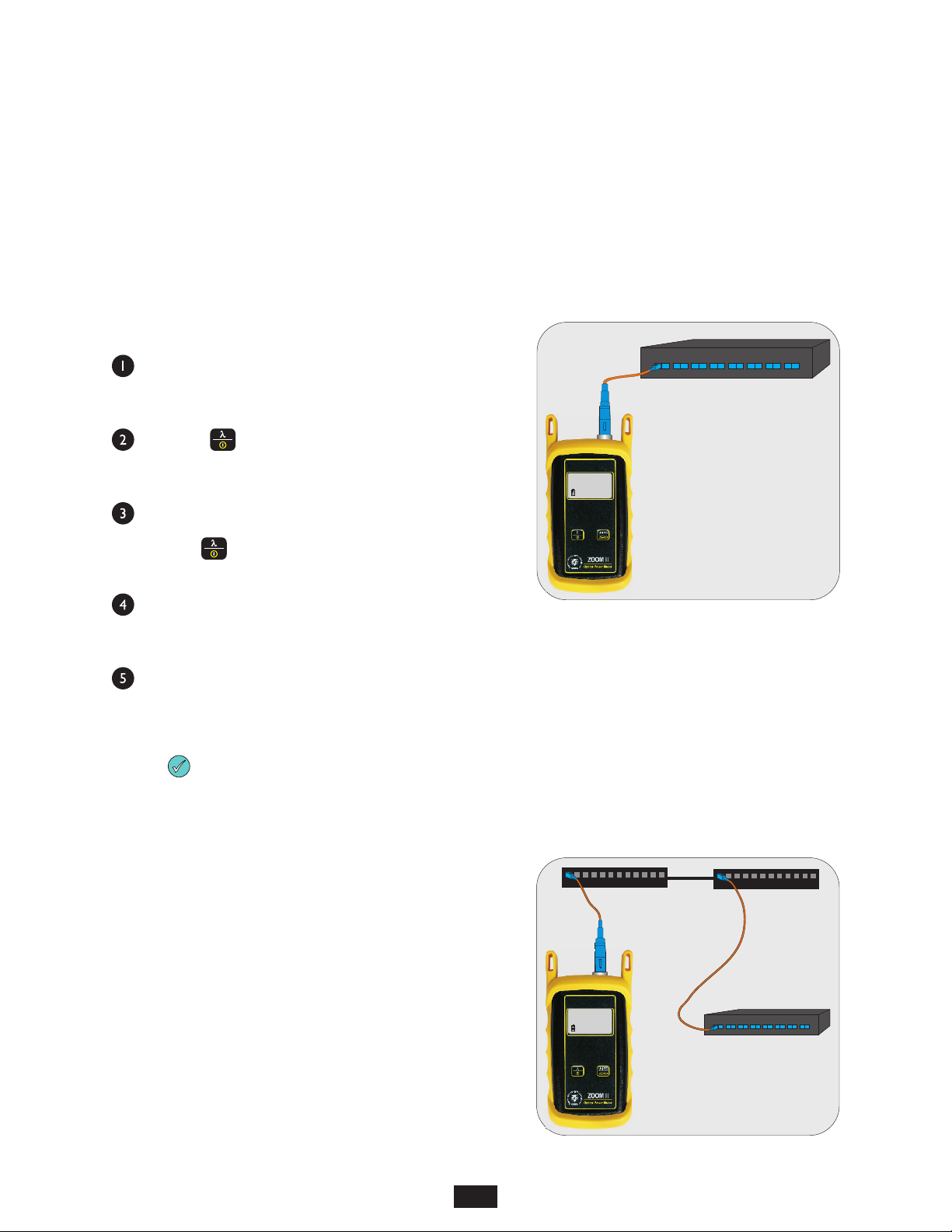
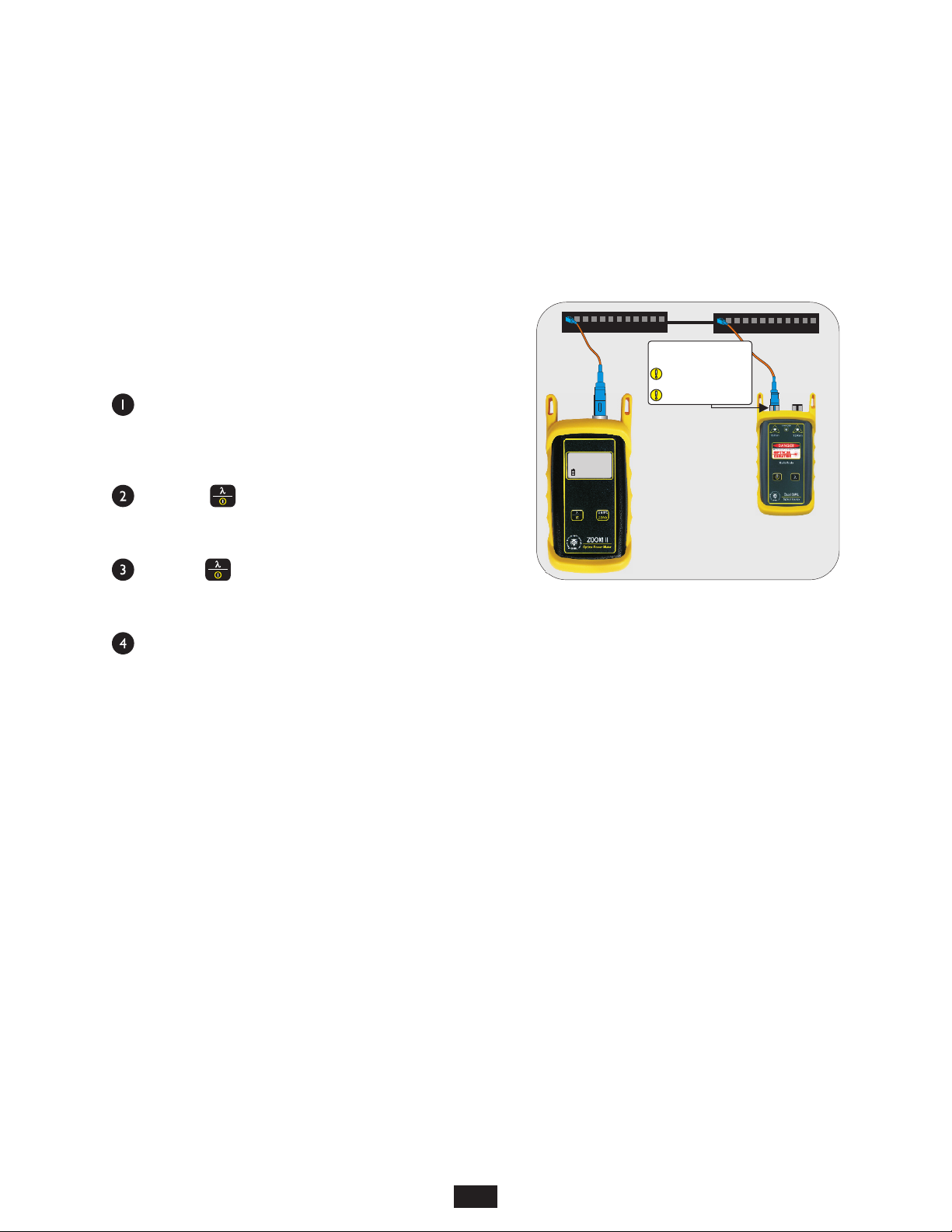
STEP 1 - Connect ZOOM 2 and Dual OWL
Connect the ZOOM 2 and Dual OWL together with an orange
multimode patch cable as shown below.
STEP 2 - Power ON the ZOOM 2
Press to power on the
ZOOM 2.
After a few seconds, the ZOOM
2 display should read ‘LO’, and
will appear similar to the
diagram shown at right.
NOTE: the wavelength and measurement units may be different
from the display at right.
STEP 3 - Set the ZOOM 2
to ‘dBm’
Press on the ZOOM 2
until the measurement units
read ‘dBm’ as shown at right.
You may need to press the
button several times.
NOTE: it is recommended to thoroughly clean and inspect all
patch cord connectors before making any connection.
OF F
ON
U NIT S
Z E R O
dBm
.8. . .8lo
-
i850
nm
dBm
.8. . .8lo
-
i850
nm
DUAL OWL
connected to
850nm port
STEP 4 - Set ZOOM 2 to 850nm
Press on the ZOOM 2
until the wavelength display
shows ‘850nm’ as shown at
right. You may need to press
the button several times.
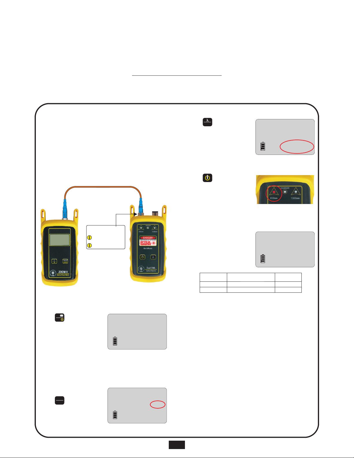
STEP 5 - Power ON the Dual OWL
Press to power on the
Dual OWL.
The 850nm indicator LED
should now be lit as shown at
right.
STEP 6 - Check optical power
The power reading that appears
on the ZOOM 2 display will
depend upon cable type.
Consult the table below for a list
of acceptable power readings.
STEP 7 - Replace the patch cable
The easiest way to troubleshoot low power levels is to try another
patch cable. Over time, patch cables can wear out or become
damaged the more they are used for optical loss testing.
Replacing the patch cable usually fixes the problem.
STEP 8 - Clean patch cables and optical ports
If the problem still exists after patch cable replacement, there
may be some debris, such as dust, dirt, or finger oil, that has
collected on the connector endface or in the equipment optical
ports.
Thoroughly clean and inspect the optical ports of the ZOOM 2
and the Dual OWL, as well as the fiber connector endfaces,
according to the brochures that have been included with this kit.
Several cleaning cycles may be required.
If the power level is still too low, even after a thorough cleaning
and inspection and patch cable replacement, contact OWL
technical support at 262-473-0643 for more information.
NOTE: the following steps are only required if the optical power
reading on the ZOOM 2 is too low.
AU T O
dBm
.8. . .8lo
-
850
nm
dBm
.20.00
-
850
nm
Core Size
62.5/125 µM
50/125 µM
Replace at
-21.00 dBm
-24.00 dBm
Acceptable Power Level
-19.0 to -21.0 dBm
-22.0 to -24.0 dBm
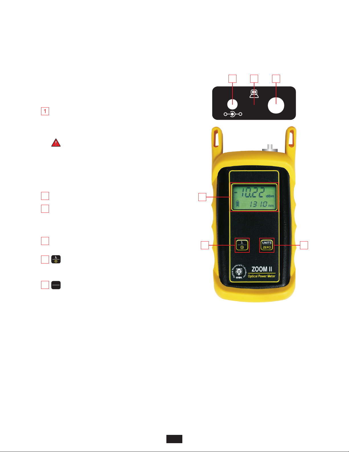
SC connectors shown here;
connector style may vary
LIGHT SOURCE
CONNECTOR PORTS
Do NOT insert APC connector
into either light source port