Tattile F01750 User manual


Reference Manual ENG
All the information in this document is subject to change without notice.
The content of this document is property of Tattile S.r.l.
This document and its parts must not be reproduced or copied without written permission
from Tattile S.r.l., and the content must not be shared with third parties or used for any
unauthorized purpose.

BASIC
Rev. D
2017-07-25
3
RMM_00042
Index
1GENERAL DESCRIPTION......................................................................................4
2CONFORMITY - COMPLIANCE ..............................................................................6
3INTERFACES CHARACTERISTICS .......................................................................10
4MECHANICAL DIMENSIONS ..............................................................................12
4.1 Camera body ................................................................................................ 12
5CONNECTIONS ..................................................................................................13
5.1 Connector Layout .......................................................................................... 13
5.2 Power supply, Signal and I/O Connector .......................................................... 13
5.3 Gigabit PoE Ethernet Socket ........................................................................... 14
5.4 Cabling the device......................................................................................... 15
6ACCESSORIES ...................................................................................................17
6.1 Pole-Mounting Adaptor................................................................................... 17
6.2 Mating Parts Kit ............................................................................................ 17
6.3 Power Supplier.............................................................................................. 17
7PRODUCT LABEL ...............................................................................................18
8INSTRUCTIONS FOR A CORRECT INSTALLATION ..............................................19
9WARRANTY .......................................................................................................19
10 REVISIONS .......................................................................................................20

Rev. D
2017-07-25
4
RMM_00042
1General description
Code
Description
Sensor
Illuminator
angle
Note
F01750
VEGA BASIC SHORT - MONO
NIR Mono 1920x1200
36°
Mono
(NIR)
F01751
VEGA BASIC SHORT - COLOR
Color 1920x1200
36°
Bayer
Color
F01752
VEGA BASIC LONG - MONO
NIR Mono 1920x1200
17°
Mono
(NIR)
F01753
VEGA BASIC LONG - COLOR
Color 1920x1200
17°
Bayer
Color
Power supply
Normal 24Vdc
PoE
IEEE 802.3af
Type
X
X (*)
(*) The GND signal of PoE power supplier must be isolated from EARTH.
Using External 24Vdc power supply
Min
Typ
Max
Power supply voltage
+24 -10%
+24
+24 +10%
V (DC)
Total power consumption
12
W
Imaging and Illumination (Monochrome models F01750 - F01752)
Image sensor
Monochrome CMOS 2/3" Global Shutter
Frame Rate
60 fps
Image resolution
1920 x 1080 pixel
Illuminator
Infrared λ= 850 nm ±15nm
Number of LEDs
8 high power LEDs.
Filter
820-880 nm
Lenses
C-mount (not included, must be ordered separately)
Imaging and Illumination (Color models F01751 - F01753)
Image sensor
Color CMOS 2/3" Global Shutter
Frame Rate
60 fps
Image resolution
1920 x 1072 pixel
Illuminator
White light 6500K
Rev. D
2017-07-25
5
RMM_00042
Number of LEDs
8 high power LEDs.
Filter
375-660 nm
Lenses
C-mount (not included, must be ordered separately)
Electronic characteristics
Gigabit Ethernet 10/100/1000
Wi-Fi IEEE 802.11 b/g/n Single 2.4 GHz band
RS485 insulated serial interface
Wiegand communication port
2 digital optoisolated PNP input
2 Relay NO output
1 Strobe output
Temperature and humidity sensor
3-axis inclinometer
Current consumption sensor
Real Time Clock
Mechanical characteristics
Size
178 x 90 x 133 mm (WxHxL)
Weight
1.25 kg
Material
Anodizing aluminium UNI 10681 –2010 -15 micron
Operating conditions
Min
Max
Operating temperature
-40
+60
°C
Operating humidity (without condensing)
10
90
%
Storage temperature
-40
+60
°C
Storage humidity (without condensing)
10
90
%
Standards
IP degree of protection (EN 60529)
IP67

Rev. D
2017-07-25
6
RMM_00042
2Conformity - Compliance
Dichiarazione CE di conformità /EC Declaration of Conformity
(Conforme a EN ISO/IEC 17050-1 /According to EN ISO/IEC 17050-1)
Produttore:
/ Manufacturer
Tattile S.r.l.
Indirizzo:
/ Address
Via Gaetano Donizetti 1/3/5
25030 Mairano (BS), Italy
Dichiara sotto la propria responsabilità che i prodotti:
/ Declares under sole responsibility that the products:
Modello, descrizione:
/ Model, description
F01750,VEGA BASIC SHORT - MONO
F01751,VEGA BASIC SHORT - COLOR
F01752,VEGA BASIC LONG –MONO
F01753,VEGA BASIC LONG - COLOR
sono in conformità ai requisiti essenziali delle seguenti direttive comunitarie:
/ are in conformity with the essential requirements the following EC directives:
Riferimento N° , titolo
/ Reference No. , title
2014/53/EU, RED Directive (1)
2011/65/EU, RoHS Directive
(1) Gli obiettivi ed i requisiti delle direttive 2014/35/EU (LVD) e 2014/30/EU (EMC) sono adempiuti nell'applicazione
dell'articolo 3.1 della direttiva 2014/53/EU. / The objectives and protection requirements of the Low Voltage Directive
2014/35/EU and EMC Directive 2014/30/EU are applied under Directive 2014/53/EU, Article 3.1.
e che sono state applicate tutte le norme e/o specifiche tecniche sotto riportate:
/ and that the standards and/or technical specifications reference below have been applied:
Art 3.1a Specifiche di Sicurezza
/ Art 3.1a Safety specifications
EN 60950-1:2006 +A11:2009 +A1:2010 +A12:2011 +AC:2011
+A2:2013 Safety IT equipment
Art 3.1b Specifiche EMC
/ Art 3.1b EMC specifications
EN 301 489-1 v2.1.1 ERM, EMC Common requirement
EN 301 489-17 v3.1.1 ERM, EMC, Specific for Wideband 2.4GHz System
EN 50293:2012 Road traffic signal system –EMC
•EN55022, emission class B
•EN61000-4-2, ESD 4kV contact / 8kV Air
•EN61000-4-3, RF radiated 10V/m AM 1kHz 80% (80-1000MHz),
3V/m AM 1kHz 80% (1.4-2.7GHz)
10Veff/m PM 50% 200Hz (900MHz, 1890MHz)
•EN61000-4-4, EFT Burst 1kV DC power, 1kV signal ports
•EN61000-4-5, Surge DC power 1kV Line to Line, 2kV Line to Ground
Surge Signal ports 0.5kV Line to Line, 1kV Line to Ground
•EN61000-4-6, RF conducted 10V (0.15-80MHz)
•EN61000-4-8, Pwr frequency magnetic field 60A/m 50Hz
Art 3.2 Spettro (Specifiche Radio)
/ Art 3.2 Spectrum (Radio spec.)
EN 300 328 v2.1.1 ERM, Spectrum for Wideband 2.4GHz System
altre norme e/o specifiche tecniche / other standards and/or technical specifications:
Altre norme / Other standards
EN 62471:2008 Photobiological safety of lamps and lamps systems
EN 62311:2008 Limit to EM Field for human exposure
EN 60068-2-1 Environmental testing. Cold test (-40°C, 16h)
EN 60068-2-2 Environmental testing. Dry Heat test (+60°C, 16h)
EN 60529 Degrees of protection provided by enclosures (IP67)
Affissa la marcatura CE dal /Affixing the EC conformity mark as from: 2017

Rev. D
2017-07-25
7
RMM_00042
FCC
Tattile herewith declares that this product is in compliance with the following US Federal
Regulation:
FCC 47 CFR Part 15 (Emission Class B)
Contains FCC ID: QOQWF111
This device complies with Part 15 of the FCC Rules. Operation is subject to the following two conditions:
(1) this device may not cause harmful interference, and (2) this device must accept any interference
received, including interference that may cause undesired operation.
This equipment complies with FCC radiation exposure limits set forth for an uncontrolled environment.
End users must follow the specific operating instructions for satisfying RF exposure compliance. This
transmitter must not be co-located or operating in conjunction with any other antenna or transmitter. This
transmitter is considered as mobile device and should not be used closer than 20 cm from a human
body.
Rev. D
2017-07-25
8
RMM_00042
WARNING! Invisible IR radiation emitted from the LED illuminator of this product. (IEC/TR 62471-2)
High levels of artificial optical radiation can cause damage to both eyes and skin. Exposure limit values have
been drawn up for such hazards. Every light system is placed within a Risk Group, which defines the level of
risk when the light is used normally, higher level higher risk group number, from 1 to 3. When the light emits
less than the exposure limit values it is categorized as Exempt Group. Evaluation of risk group is made at
0,2m distance, that is the minimum hazard distance considered.
The hazard distance (HD) is the point furthest from the illuminator at which the Exempt Group exposure limit
is exceeded.
Illuminator risk group and hazard distance evaluation:
F01750
IR illuminator lens 36° (wavelength 860nm, ±15nm spectral bandwidth @ 50% of max intensity)
Hazard
Ultraviolet
hazard
200 - 400 nm
(Es/Euva)
Retinal blue light
hazard
300 - 400 nm
(Lb)
Retinal blue light
or thermal
hazard
400 - 780 nm
(Lr)
Cornea/lens
infrared hazard
780 - 3000 nm
(Eir)
Retinal thermal
hazard, weak
visual stimulus
780 - 1400 nm
(Lir)
Risk Group
Exempt Group
Exempt Group
Exempt Group
Exempt Group
Exempt Group
HD
–
–
–
–
–
HD = Hazard distance (in meters).
The product is in Exempt Group no labelling required.
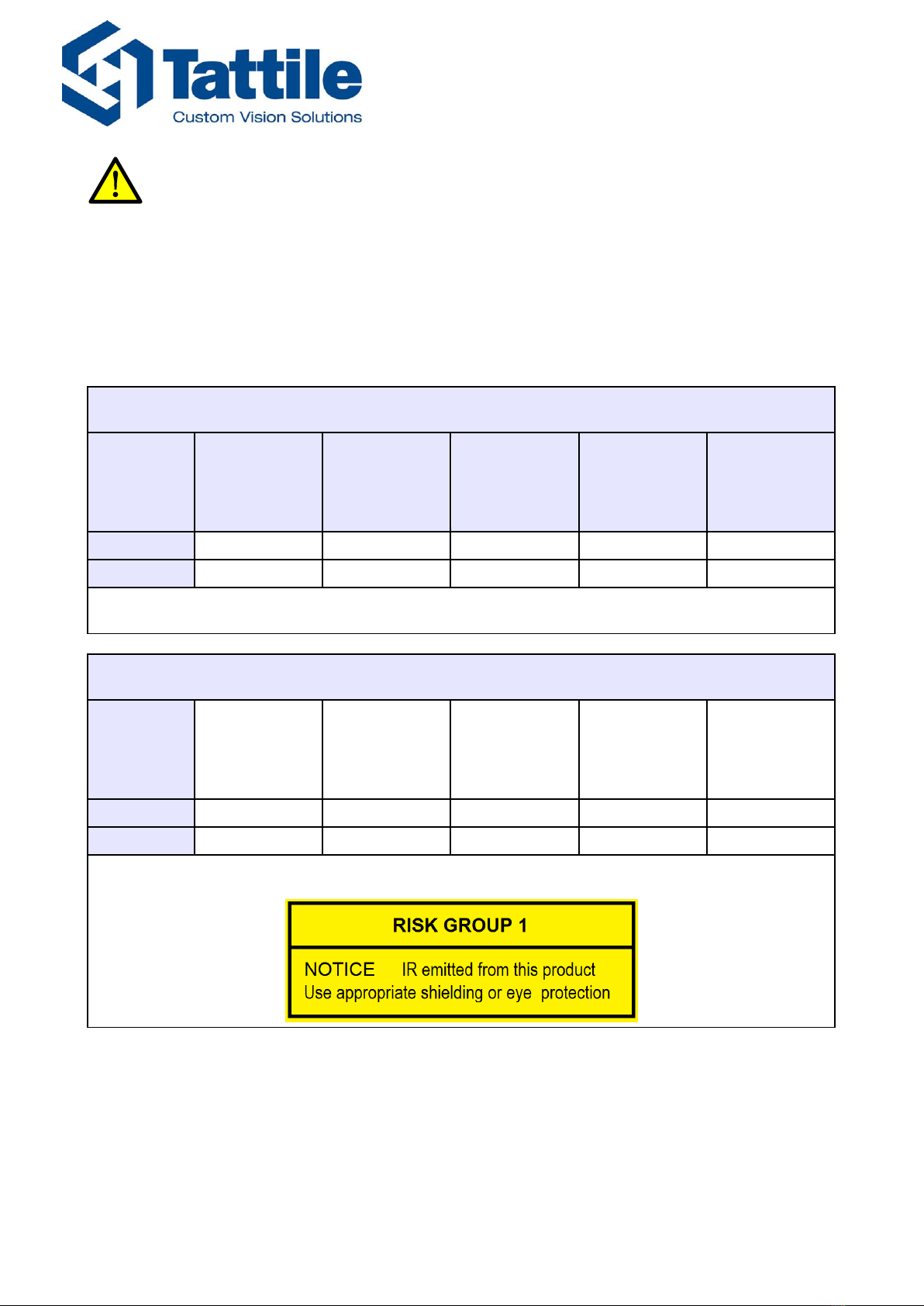
F01752
IR illuminator lens 17° (wavelength 860nm, ±15nm spectral bandwidth @ 50% of max intensity)
Hazard
Ultraviolet
hazard
200 - 400 nm
(Es/Euva)
Retinal blue light
hazard
300 - 400 nm
(Lb)
Retinal blue light
or thermal
hazard
400 - 780 nm
(Lr)
Cornea/lens
infrared hazard
780 - 3000 nm
(Eir)
Retinal thermal
hazard, weak
visual stimulus
780 - 1400 nm
(Lir)
Risk Group
Exempt Group
Exempt Group
Exempt Group
Risk Group 1
Exempt Group
HD
–
–
–
0,23 m
–
HD = Hazard distance (in meters).
The product is in excess of Exempt Group limit so it is labelled:
Rev. D
2017-07-25
9
RMM_00042
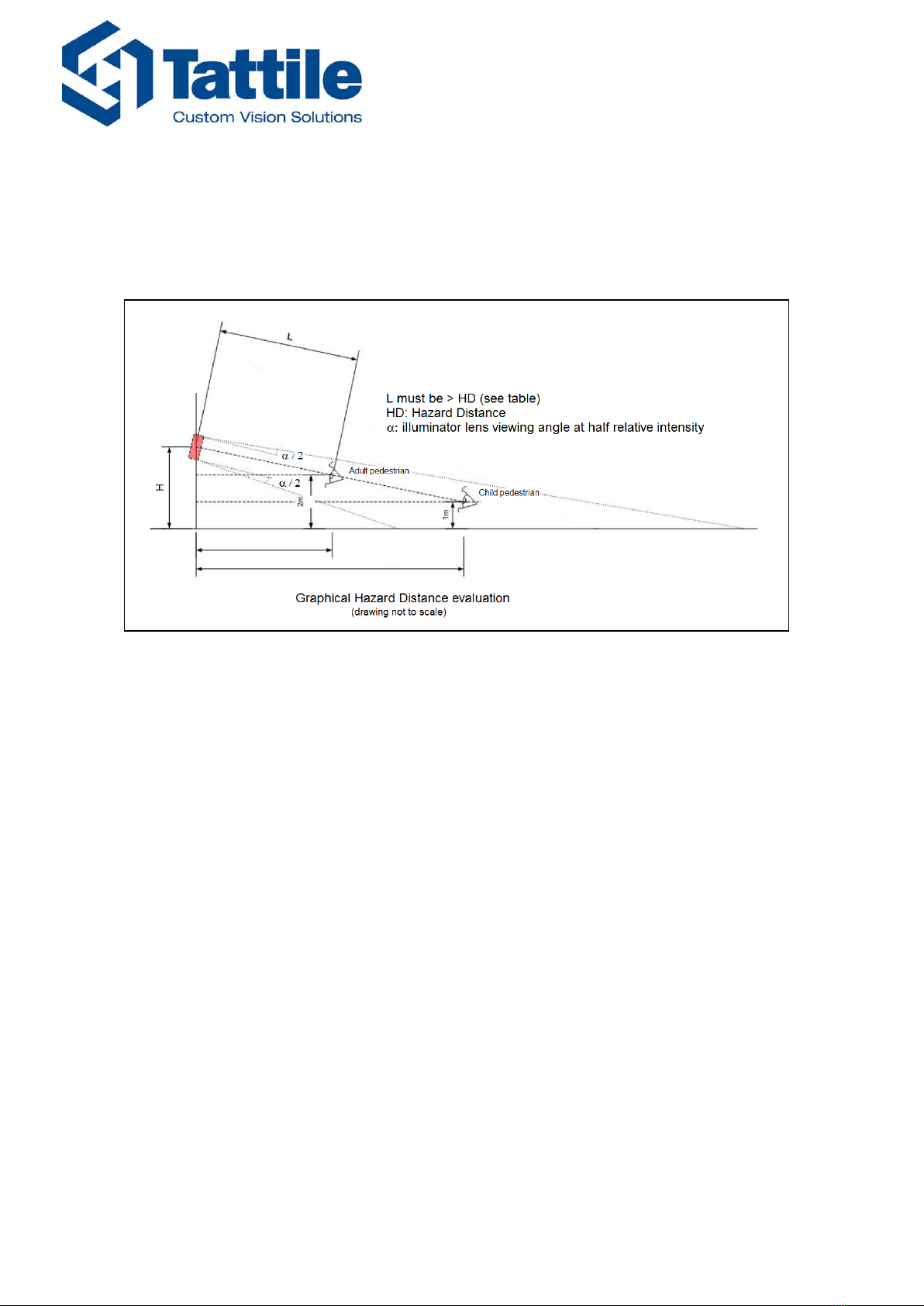
For illuminator exceeding Exempt Group limit camera shall be installed as detailed in the figure
below, at distance L>HD, there is no risk to the public.
Operator or maintenance staff working in front of the camera, facing the illuminator, at
distance less than HD must use appropriate shielding or eye protection, as written in the
labelling.
Hazard Distance evaluation
Rev. D
2017-07-25
10
RMM_00042
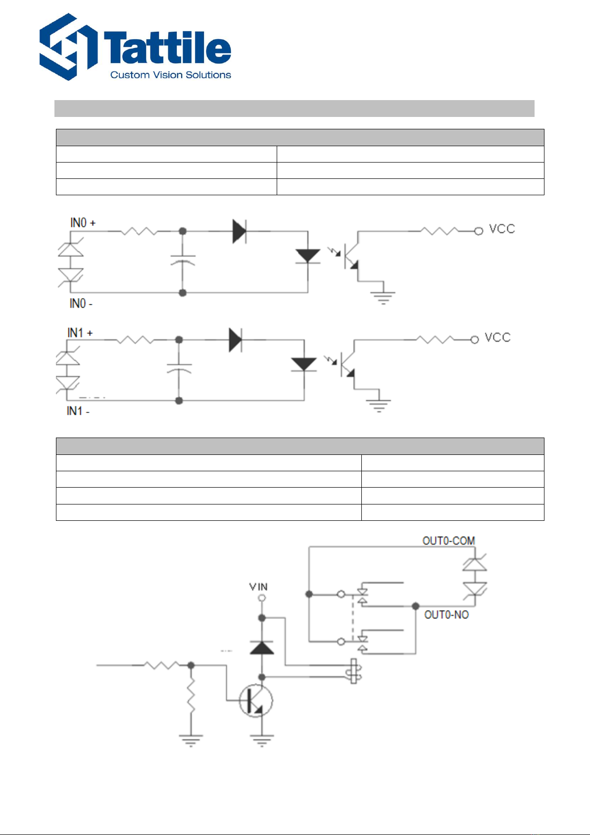
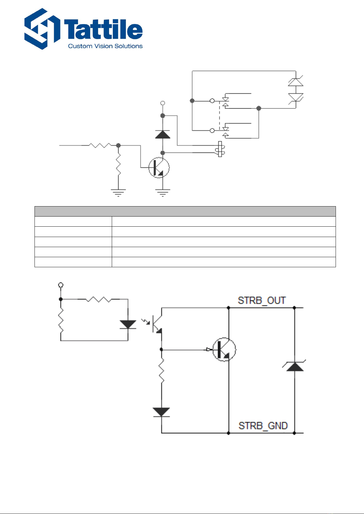
3Interfaces characteristics
Digital input
Type
Optoisolated PNP
Channels
2
Voltage
24 V DC
Relay output
Type
Normally open
Channels
2
Max switching voltage
21 V AC / 30 V DC
Max switching current
0.5 A
Rev. D
2017-07-25
11
RMM_00042
OUT1-COM
OUT1-NO
V IN
Strobe output
Type
Optoisolated open collector
Channels
1
Max voltage
24 V DC +10%
Min voltage
3.3 V DC -10%
Max current
50 mA

Rev. D
2017-07-25
12
RMM_00042
4Mechanical dimensions
4.1 Camera body
Ref.
Description
1
Lens
2
IR Illuminator
3
Extruded body
4
Cover
5
Cable Glands

Rev. D
2017-07-25
13
RMM_00042
5Connections
5.1 Connector Layout
A - RJ45 Ethernet Socket
B - Power Supply, Signal I/O Socket
1 2
17 18
5.2 Power supply, Signal and I/O Connector
Pin
Signal name
Description
1
OUT0-NO
Relay Output 0, NO contact
2
OUT0-COM
Relay Output 0, COM contact
3
OUT1-NO
Relay Output 1, NO contact
4
OUT1-COM
Relay Output 1, COM contact
5
STRB_OUT
Strobe Output
6
STRB_GND
Strobe Output ground
7
IN1 +
Digital input 1, positive (+)
8
WD0
Wiegand communication D0
9
IN1 -
Digital input 1, negative (-)
10
WD1
Wiegand communication D1
11
IN0 +
Digital input 0, positive (+)
12
SER-A (+)
RS485 serial port (+)
13
IN0 -
Digital input 0, negative (-)
14
SER-B (-)
RS485 serial port (-)
15
GNDS
Wiegand and RS485 ground
16
VIN+
Power input +24 V DC
17
EARTH
Functional earth, device chassis
18
VIN-
Power input ground (GND)
Mating Connector included
The maximum cable diameter accepted by the cable glands is 8mm.
To guarantee the best connection of the wires to the connector please use pin connectors.
A
B
12
17 18
Rev. D
2017-07-25
14
RMM_00042
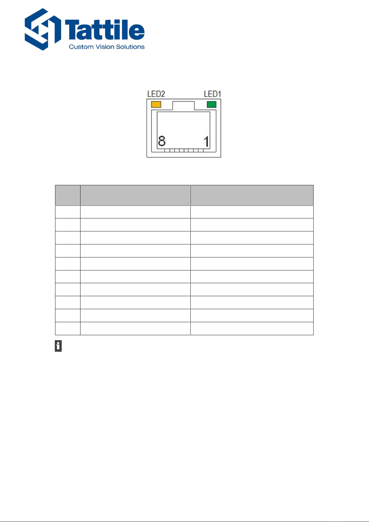
5.3 Gigabit PoE Ethernet Socket
RJ45 Gigabit connector
Mating connector RJ45 PLUG included
Pin
Gigabit mode (1000base-T)
10/100 mode (10base-
T/100base-TX)
1
MX1+
TX+
2
MX1-
TX-
3
MX2+
RX+
4
MX3+
5
MX3
6
MX2
RX
7
MX4+
8
MX4
LED1
Link LED
Link LED
LED2
Activity LED
Activity LED

Rev. D
2017-07-25
15
RMM_00042
5.4 Cabling the device
1) Remove the three M5 Allen-screws placed on the left side of the camera.
2) Remove the left cover being careful not to break the gasket.
3) Open the cable glands and insert the power/signals and Ethernet cables through them.
4) Make the connections following the pinouts indicated in the 5.1 & 0 paragraphs.

Rev. D
2017-07-25
16
RMM_00042
To guarantee the best connection of the wires to the connector please use pin connectors.
5) Connect the cables to the device. Make sure you place and correctly bend the cable
inside the compartment to prevent it from being damaged when closing the left cover.
6) Appropriately tighten the cable glands.
7) Place the cover again on the device side and tighten the Allen-screws respecting a
tightening torque of 2.5 N·m.
Rev. D
2017-07-25
17
RMM_00042
6Accessories
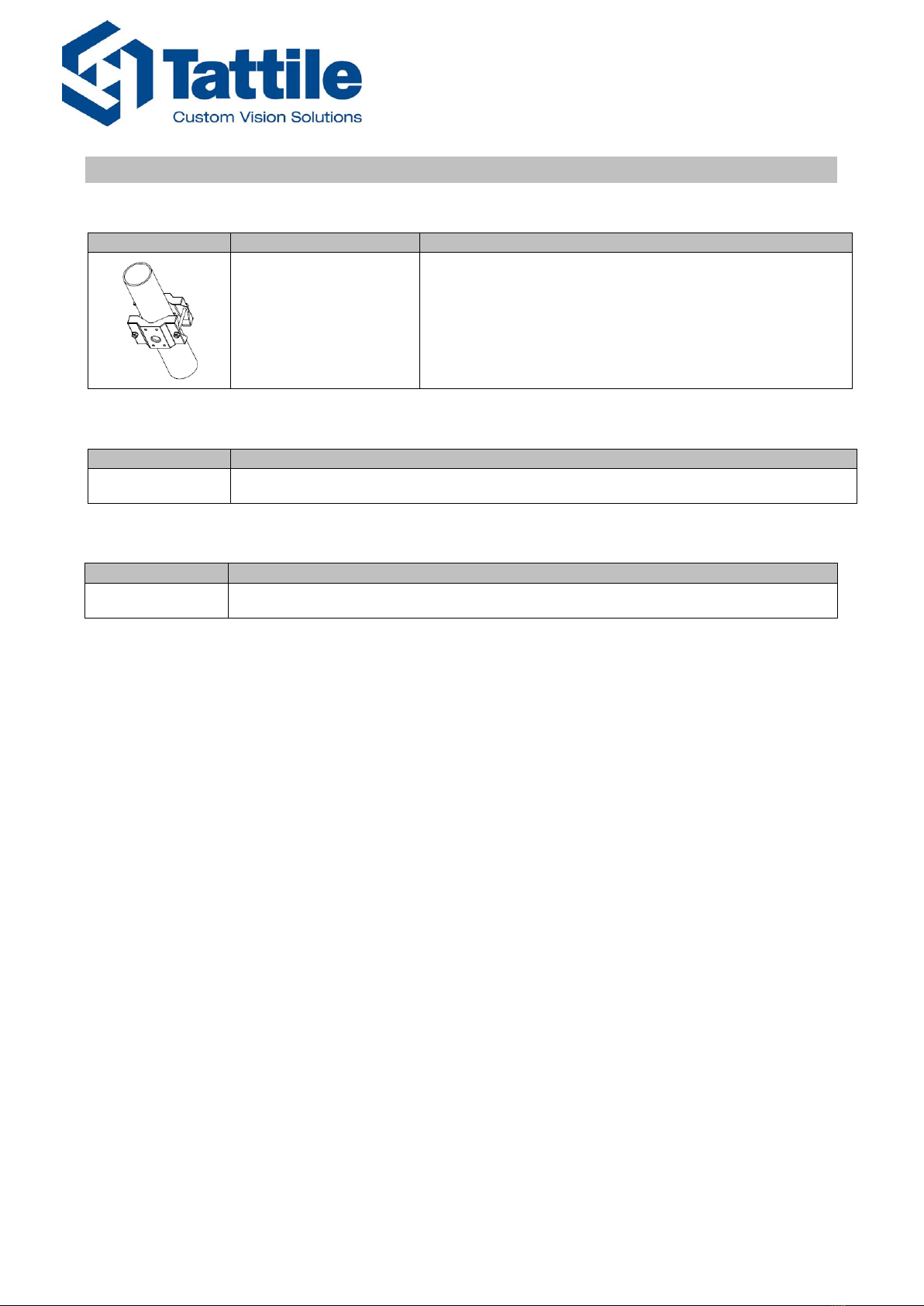
6.1 Pole-Mounting Adaptor
Drawing
Ordering Code
Note
T19841
Pole-Mounting Adaptor for poles with diameter
between 65mm and 110mm.
6.2 Mating Parts Kit
Ordering Code
Note
T19687
Mating parts kit (included in the package)
6.3 Power Supplier
Ordering Code
Note
F01836
Power Supplier 24 V DC, 5 A

Rev. D
2017-07-25
18
RMM_00042
7Product label
Ref.
Description
1
Tattile logo
2
Product Part Number
3
Product Name
4
Product Serial Number
5
Serial Number Barcode (code 128)
6
Ethernet Mac Address
7
Mac Address Barcode (code 128)
8
Revision
9
CE mark
10
Rated Voltage and current, symbol for nature of supply

Rev. D
2017-07-25
19
RMM_00042
8Instructions for a correct installation
To guarantee a good functioning of the device all the instructions contained in this manual
must be respected. If the installation does not follow the instructions below, Tattile declines all
responsibility for anomalous behaviours of the device:
Always observe the polarities of the power supplies and the power requirements
specified in this manual.
Always observe the polarities of the input/output signals and their electrical
characteristics.
Mount the equipment on a mechanically stable structure.
Remove the power supply voltage from the camera before unplugging the power
connector.
Turn off all electrical power before making or breaking any electrical connections to
avoid damaging the device.
Use a power supplier with SELV output.
The camera shall be reachable only by maintenance operator.
9Warranty
The warranty covering the product is invalid if:
The device has been opened or disassembled.
The label is removed and the serial number cannot be read.
Incorrect connection of the power supply and/or the input-output circuitry damaged the
device.
The indications written in the previous paragraph were not respected and this led to
damages.
Damages occurred during the delivery or after an incorrect storage.
These conditions apply to all the equipment supplied with the system.
Rev. D
2017-07-25
20
RMM_00042
10 Revisions
Rev.
Date
Description
Prepared by
Approved by
Pre. A
2016-11-23
Preliminary Version
P. Forti
I. Paderno
Pre. B
2017-02-24
Updating of the Preliminary version,
including Products Name, note about
Power Supply PoE (page 4) added.
New code of pole-mounting bracket
P. Forti
I. Paderno
Pre. C
2017-03-31
General revision of the document
R. Marchioni
I. Paderno
Pre. D
2017-07-25
Revision document and update scheme,
update Conformity Compliance and
added warning IR radiation.
P. Forti
A. Tonini
Please recycle packaging after use!
Packaging materials are recyclable. Please do not dispose packaging into unsorted
waste but recycle it.
At the end of their life cycle all the electronic products must be sent to a
Waste Electrical and Electronic Equipment recycling center!
This manual suits for next models
3
Table of contents
Other Tattile Measuring Instrument manuals


