ASSEMBLAD OPA-105 User manual

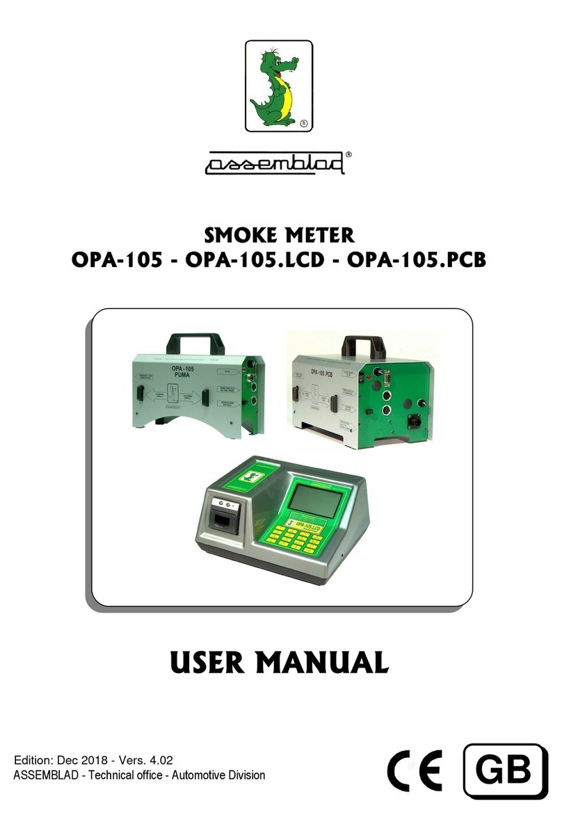
OPA-105 OPA-105.PCB OPA-105.LCD Serve manual
SMOKE METER
OPA-105 • OPA-105.LCD • OPA-105.PCB
SERVICE MANUAL
Ed.: October 2010 - Vers. 3.10
ASSEMBLAD - Ufficio Tecnico - Divisione A tomotive
S105gb31
ASSEMBLAD S.r.l. - Costr zioni Elettroniche - Servizio Assistenza Tecnica Clienti
Via Vittorio Veneto, 40 - 50013 Campi Bisenzio - Firenze - Italia
Tel. 055-890485 - Fax. 055-890496 - E-mail: inf[email protected] –Web: www.assemblad.it
1
GB

OPA-105 OPA-105.PCB OPA-105.LCD Serve manual
Notes
ASSEMBLAD S.r.l. - Costr zioni Elettroniche - Servizio Assistenza Tecnica Clienti
Via Vittorio Veneto, 40 - 50013 Campi Bisenzio - Firenze - Italia
Tel. 055-890485 - Fax. 055-890496 - E-mail: inf[email protected] –Web: www.assemblad.it
2

OPA-105 OPA-105.PCB OPA-105.LCD Serve manual
INDEX
1 GENERAL WARNINGS .................................................................................................... 4
2 THE PROGRAM PUMADOCTOR .................................................................................... 4
2.1 PUMADOCTOR COMMANDS ........................................................................................ 6
2.2 CALIBRATION OF SMOKE METER ............................................................................... 8
2.2.1 DARK LEVEL TUNING .............................................................................................. 8
2.2.2 FILTER TUNING ....................................................................................................... 8
2.2.3 CALIBRATION CHECK ............................................................................................. 9
2.3 CALIBRATION OF OIL TEMPERATURE SENSOR ..................................................... 10
2.4 FIRMWARE UPDATE .................................................................................................... 10
3 SETTING THE SMOKE VALVE ..................................................................................... 11
4 THE DISPLAY AND THE MENU .................................................................................... 12
4.1 FIRST MENU ................................................................................................................. 12
4.2 MAINTENANCE ............................................................................................................. 12
4.3 SET-UP .......................................................................................................................... 13
5 CONNECTIONS TO CPU BOARD ................................................................................. 14
6 CONNECTIONS TO VISUAL BOARD ........................................................................... 15
7 CONVERSION TABLE ................................................................................................... 16
TROUBLESHOOTING ................................................................................................... 17
ASSEMBLAD S.r.l. - Costr zioni Elettroniche - Servizio Assistenza Tecnica Clienti
Via Vittorio Veneto, 40 - 50013 Campi Bisenzio - Firenze - Italia
Tel. 055-890485 - Fax. 055-890496 - E-mail: inf[email protected] –Web: www.assemblad.it
3

OPA-105 OPA-105.PCB OPA-105.LCD Serve manual
1 GENERAL WARNINGS
This man al list the service an recalibration operations for the smoke meter OPA-105
family, these operations are reserved only to the technical persons a thorized from
Assemblad.
The inacc racy of the operations can damaged the instr ment.
The other information abo t the instr ments are in the ser man al.
2 THE PROGRAM PUMADOCTOR
The software PUMADOCTOR is a mod le of program DRAGON. It is sed for servicing
the Assemblad smoke meter. This program r n nder Windows.
At the beginning it is req ired a password, if it is not known press ENTER.
Some commands are reported in grey, they are not available witho t the password or
beca se not implemented or reserved to specific models,
ASSEMBLAD S.r.l. - Costr zioni Elettroniche - Servizio Assistenza Tecnica Clienti
Via Vittorio Veneto, 40 - 50013 Campi Bisenzio - Firenze - Italia
Tel. 055-890485 - Fax. 055-890496 - E-mail: inf[email protected] –Web: www.assemblad.it
4
1 2 3 4 5 6
7 9 10 11 12 13

OPA-105 OPA-105.PCB OPA-105.LCD Serve manual
The desktop is divided in the following parts:
1. SMOKEMETER DATA – it is placed on the left of the top, it reports the data
recorded in the eeprom of the smoke meter.
2. VERSION – it is nder the label 'P ma Doctor'. There are always new versions
with new f nctions or error corrections.
3. PARAMETERS – this is the most important windows, it is placed in the centre
and report the val es of the analog channels and the calc lated parameters,
each channel has the val es in 3 nits, Reals, mVolts and A/D nit.
4. SMOKEMETER STATE – it is placed on the top of the desktop, it reports the
stat s of the smoke meter and the type of smoke valve installed.
5. MESSAGE WINDOW – it is displaced in the pper right side, there are the
instr ctions and the data req ests for some commands.
6. SMOKE VALVE – it is displaced in the pper right corner, it show the presence
and the type of valve for the smoke.
7. COMUNICATION SETTINGS – this is the lower side of the desktop, set the
n mber of the port connected to the smoke meter, the right connection with the
instr ment is showed with the green window.
8. MODEL – it is in the lower side and show the model of the smoke meter
connected.
9. ERROR MESSAGE – it is placed on the left and report the error messages
received from the instr ment, when the error is solved the message is deleted.
10.COMMUNICATION STATUS – it is displaced in the lower centre, it show the
condition of the serial comm nication with the smoke meter.
11.LOG - it is displaced in the lower side, this key start or stop the memorise of all
val es received from the instr ment in the file p madoctor.csv
12.OTHER INFORMATIONS – some commands will be show specific windows
with the instr ctions, photos etc. to perform the operations..
13.MENU – it is placed on the right of the desktop, it report all the commands and
proced res, some of these have several s b-men with the instr ctions to be
exec ted. The commands reported in grey colo r are not available.
ASSEMBLAD S.r.l. - Costr zioni Elettroniche - Servizio Assistenza Tecnica Clienti
Via Vittorio Veneto, 40 - 50013 Campi Bisenzio - Firenze - Italia
Tel. 055-890485 - Fax. 055-890496 - E-mail: inf[email protected] –Web: www.assemblad.it
5

OPA-105 OPA-105.PCB OPA-105.LCD Serve manual
2.1 PUMADOCTOR COMMANDS
The list of commando has 3 levels of enable:
-witho t password are activated only the commands that show the instr ment stat s
and make basically commando, the typical ser is the operator.
-with the service password are activated near all commands, with these is
achievable to perform the calibration proced res, the typical ser is the technical
service operator.
-With the Assemblad password are activated all commands, also the ones for the
initial settings and test, the se is reserved in prod ction department.
Command Enable Description
SERIAL PORT SETTING Close all serial ports, empty the b ffers and
restore the connection.
RESET Reset the instr ment, it is the same to t rn
off/on.
INSTRUMENT DATA Service Change expiring data.
Assemblad Change all instr ment data.
DATA AND TIME
SETTING
Set the instr ment clock with the date and
time of the PC, this f nction works only with
models with own RTC.
AUTO-ZEROING Perform an a to-zero, it don’t work in warm-
p stat s, if the instr ment is in stand-by
stat s a tomatically go in meas re stat s.
RESET OF
MEASUREMENT PEACK
Send the command MCTCNET RSSE AP
STAND-BY Send the command MCTCNET RSSE SB
SENSORS SETTING Service Set the reference val es for temperat re and
press re sensors.
REFERENCE FILTER
CHECK
Proced re to verify the meas rement state
with the check filter of the instr ment.
DARK LEVEL TUNING Service Proced re to perform the end of range
setting.
FILTER TUNING Service Proced re for the calibration of the
instr ment with a certificate ne tral density
filter. Don’t se with the check filter.
CALIBRATION CHECK Service Proced re to verify the calibration of the
instr ment in all range with the se of several
ne tral density certified filters, with the print
of the report..
REPRINT CALIBRATION
REPORT
Assemblad Special f nction.
TEST SMOKE VALVE Check of the f nctionality of the smoke valve
and its optical sensors.
READ MEMORY
PARAMETER
Assemblad Reading the val e of a parameter.
WRITEMEMORY Assemblad Storing the val e of a parameter.
ASSEMBLAD S.r.l. - Costr zioni Elettroniche - Servizio Assistenza Tecnica Clienti
Via Vittorio Veneto, 40 - 50013 Campi Bisenzio - Firenze - Italia
Tel. 055-890485 - Fax. 055-890496 - E-mail: inf[email protected] –Web: www.assemblad.it
6

OPA-105 OPA-105.PCB OPA-105.LCD Serve manual
PARAMETER
LOAD MEMORY
PARAMETERS
Service Load all the parameters val e from a file.
SAVE MEMORY
PARAMETERS
Service Save the val e of all parameters in a file.
FIRMWARE UPDATE Service Update the instr ment firmware thro gh the
service serial port.
VISUAL INITIALIZING Assemblad Special f nction.
GARAGE DATA Store the c stomer data sed in the
instr ment printo t.
VISUAL MEMORY PAR.
READING
Assemblad Reading the val e of a vis al board
parameter.
VISUAL MEMORY PAR.
WRITING
Assemblad Storing the val e of a vis al board
parameter.
LOAD VIEWER
PARAMETERS
Service Load all the vis al board parameters val e
from a file.
SAVE VIEWER
PARAMETERS
Service Save all the vis al board parameters val e
from a file.
VISUAL FIRMWARE
UPDATE
Service Update the vis al board firmware.
UNLOCK CODE Instr ment activation, typically after a
software pdate.
REQUEST UNLOCK
CODE
Compilation and printing the form to sent to
req est the activation code.
ASSEMBLAD S.r.l. - Costr zioni Elettroniche - Servizio Assistenza Tecnica Clienti
Via Vittorio Veneto, 40 - 50013 Campi Bisenzio - Firenze - Italia
Tel. 055-890485 - Fax. 055-890496 - E-mail: inf[email protected] –Web: www.assemblad.it
7

OPA-105 OPA-105.PCB OPA-105.LCD Serve manual
2.2 CALIBRATION OF SMOKE METER
To perform the calibration of the smoke meter, exec te in seq ence the following
commands:
DARK LEVEL TUNING
FILTER TUNING
CALIBRATION CHECK
2.2.1 DARK LEVEL TUNING
Before to make the dark level t ning
t rn on the instr ment for almost 15
min tes to have a good thermal
stabilization.
Phase 1 - Extract the rear window
(the one near the smoke inp t) and
insert a dark window, it can be the
“window” inserted in the opposite
side, with the black smooth face
inside, directed to the connector
panel side.
Phase 2 - When it is finished extract
the dark windows and insert the
rear window, press the req est key.
Phase 3 - Wait for the end of a to-
zeroing, when it is finished it come
back to the main men .
Make attention to insert the dark windows or the rear window when it is req ested, the
exchange of the filters or the wrong insertion ca se a wrong calibration.
2.2.2 FILTER TUNING
To make the calibration se a
certified ne tral density filter with an
opacity between 1,6 and 1,8 K.
Phase 1 - Extract the rear window.
Phase 2 - Waiting for a to-zeroing.
Phase 3 - Insert the val e of the
calibration filter, remember to se
the comma as decimal divider,
press Calibrates key (F1) to
proceed with the calibration, press
the Cancel key (End) to come back
to the main screen.
ASSEMBLAD S.r.l. - Costr zioni Elettroniche - Servizio Assistenza Tecnica Clienti
Via Vittorio Veneto, 40 - 50013 Campi Bisenzio - Firenze - Italia
Tel. 055-890485 - Fax. 055-890496 - E-mail: inf[email protected] –Web: www.assemblad.it
8

OPA-105 OPA-105.PCB OPA-105.LCD Serve manual
2.2.3 CALIBRATION CHECK
To perform the calibration check are
needed 3 certified ne tral density
filters. Verify that filters are perfectly
cleaned, after the se keep in a
place witho t d st and light.
Set the smoke meter in meas re
and exec te the command.
Phase 1 - Extract the rear window.
Phase 2 - Waiting for a to-zeroing.
Phase 3 - F ll light reading check.
Verify a reading of 0, press Record
key (F5) to contin e.
Phase 4 - Insert the nominal filter
val e, insert the filter and verify if
the reading val e is in the admitted
limits, if it is not so, try to extract an
reinsert the filter or to clean the filter, press Record key (F5) to contin e.
Repeat Phase 4 for the other 2 filters, press the key to contin e.
Phase 5 – Verify the end range reading check, press Record key (F5) to contin e and
Print key (F4) for the certificate.
Select the certificate lang age, year of man fact ring and OPA-105.
Print the report
ASSEMBLAD S.r.l. - Costr zioni Elettroniche - Servizio Assistenza Tecnica Clienti
Via Vittorio Veneto, 40 - 50013 Campi Bisenzio - Firenze - Italia
Tel. 055-890485 - Fax. 055-890496 - E-mail: inf[email protected] –Web: www.assemblad.it
9

OPA-105 OPA-105.PCB OPA-105.LCD Serve manual
2.3 CALIBRATION OF OIL TEMPERATURE SENSOR
The oil probe of the smoke meter OPA-105 is different to the oil probe of the smoke meter
OPA391.
To make this calibration yo is needed of an acc rate thermometer (max err. 0.5 °C)
Connect the smoke meter to a PC with the program PUMADOCTOR, connect the oil
temperat re sensor and place the thermometer in contact to the end of the sensor, wait
for the stabilization of the temperat re.
Exec te the command SENSORS SETTING.
The system req ired “Insert the press re val e”, confirm the val e with ENTER key.
The system req ired “Insert the oil temperat re val e”, write the val e reported in the
reference thermometer and confirm with ENTER.
Confirm the val es of smoke temperat re and chamber temperat re with ENTER key.
Verify the val es of the 3 temperat re in the centre window.
To have the best reg lation is needed to place the oil temperat re sensor and the
thermometer at a stabilized temperat re of abo t 85 °C, beca se this is the typical work
val e.
2.4 FIRMWARE UPDATE
Attention: An error or a break in this proced re can delete the boot firmware stored into
the microprocessor, if this occ r the instr ment will not work and will be need to ret rn it to
Assemblad to re-program.
To make the pdate se a cable connection, better witho t serial adapters.
Get ready the program file, the name is Opa105_XXXX.s19, with XXXX is the version
n mber.
Connect the instr ment to the PC, t rn on, verify that comm nication is ON.
Verify the instr ment software version reported in the label FW Version.
If it m st be pgraded, in the window men select FIRMWARE UPDATE.
Remove the cover as showed, with reference to pict re in chapter CONNECTION ON
CPU BOARD, select the connector RS232-MCTCnet, take o t it and place in the near
connector RS232service, be caref l to don’t disconnect other connectors, for
OPA105.LCD m st be sed the program cable connected to the RS232service and to the
PC.
Select the arrow key UP. Select the program file, press OK.
Wait for the end of programming, restore the connector in RS232-MCTCnet.
Select the arrow key UP.
Verify that instr ment led is flashing and that comm nication is ON, verify the instr ment
software version.
ASSEMBLAD S.r.l. - Costr zioni Elettroniche - Servizio Assistenza Tecnica Clienti
Via Vittorio Veneto, 40 - 50013 Campi Bisenzio - Firenze - Italia
Tel. 055-890485 - Fax. 055-890496 - E-mail: inf[email protected] –Web: www.assemblad.it
10

OPA-105 OPA-105.PCB OPA-105.LCD Serve manual
3 SETTING THE SMOKE VALVE
T rn on the instr ment and wait the end of warm- p, verify the STAND-BY stat s, rotate
the eccentric joined to set the n t (A) in the position of clock 7:00. The rotation is hard for
the gearmotor.
A
On the
near panel, slacken the 2 screws of the photocell board, place the board to position the
thin layer to have open the pper photocell, see point B.
B
C
Close the 2 screws on the panel, on the PC send the command STAND-BY to set the
instr ment in MEASURE stat s.
Verify that the thin layer go in an pper position, opening the lower photocell.
Repeat the command STAND-BY to move the thin layer p and down, verifying the
correct opening of the relative photocells .
If the system don’t work properly slacken the 2 screws of the photocell board and set the
board to achieve the right position, close the 2 screws on the panel.
ASSEMBLAD S.r.l. - Costr zioni Elettroniche - Servizio Assistenza Tecnica Clienti
Via Vittorio Veneto, 40 - 50013 Campi Bisenzio - Firenze - Italia
Tel. 055-890485 - Fax. 055-890496 - E-mail: inf[email protected] –Web: www.assemblad.it
11

28/10/09 OPA-105.LCD .
1 – VEHICLE DATA
2 – AMBIENT DATA
3 – LIMITS SETTING
4 – INSTRUMENTS
-------------------
5 – MAINTENANCE
- LANGUAGE
MAINTENANCE .
1 – Date/time setup
2 – Garage data
3 – RPM-meter data
4 – Services
5 – Set-Up
– Instrument data
OPA-105 OPA-105.PCB OPA-105.LCD Serve manual
4 THE DISPLAY AND THE MENU
The smoke meter OPA-105.LCD has a display to show the men and the meas rement.
Some part may be not enabled, some other reserved for technical service.
4.1 FIRST MENU
This men is displayed when we t rn on the instr ment and when we come-back from
other men .
In the high-left corner is showed the data, in the pper centre is reported the selected
instr ment, to operate the choice p sh the key-n mber.
After a short time the backlight is switched-off, p sh the ESC key to restore.
Use the arrow keys to set the contrast of the LCD, this f nction work only in this men .
4.2 MAINTENANCE
In this men are selectable setting and service f nctions.
The choice Service and Set- p are reserved to the technical service by means of a
password.
ASSEMBLAD S.r.l. - Costr zioni Elettroniche - Servizio Assistenza Tecnica Clienti
Via Vittorio Veneto, 40 - 50013 Campi Bisenzio - Firenze - Italia
Tel. 055-890485 - Fax. 055-890496 - E-mail: inf[email protected] –Web: www.assemblad.it
12

SET-UP .
1 – HC residue : No
2 – Leak check : No
3 – Autostandby : 10 min.
4 – Timeout PRN : 2 sec.
5 – Pwd modify
– Set Parameter
OPA-105 OPA-105.PCB OPA-105.LCD Serve manual
4.3 SET-UP
1 – Pwd modify : modify the password to enter in the men reserved to servicing.
2 – Modify the smoke meter parameter val e.
ASSEMBLAD S.r.l. - Costr zioni Elettroniche - Servizio Assistenza Tecnica Clienti
Via Vittorio Veneto, 40 - 50013 Campi Bisenzio - Firenze - Italia
Tel. 055-890485 - Fax. 055-890496 - E-mail: inf[email protected] –Web: www.assemblad.it
13

OPA-105 OPA-105.PCB OPA-105.LCD Serve manual
5 CONNECTIONS TO CPU BOARD
POWER SUPPLY
CHAMBER HEATING
FANS
+
LED BOARD
MOTORIDUT.
RPM
RS232-MCTCnet
POWER BLUET. (1)
OIL TEMPER.(2-3)
RS232 service
SMOKE TEMPER. (1-2)
CHAMBER TEMPER. (3-4)
OPTICAL SENSOR
PANEL LED
ASSEMBLAD S.r.l. - Costr zioni Elettroniche - Servizio Assistenza Tecnica Clienti
Via Vittorio Veneto, 40 - 50013 Campi Bisenzio - Firenze - Italia
Tel. 055-890485 - Fax. 055-890496 - E-mail: inf[email protected] –Web: www.assemblad.it
14

OPA-105 OPA-105.PCB OPA-105.LCD Serve manual
6 CONNECTIONS TO VISUAL BOARD
LCD KEYBOARD
VCC
VCC
VCC
Power printer
Backlight LCD
Fan
Data printer
Serial B-TTL
Serial C-TTL
--Rs232-1-PC
Rs232-5-RPM
--Rs232-2-gas anal.
Rs232-6-EOBD int.
--Rs232-3-smoke m.
Rs232-7-a x1
--Rs232-4-speed m.
Rs232-8-a x2
--o t1-o t2
sens2
spare spare
sens3 sens1 a xin
ASSEMBLAD S.r.l. - Costr zioni Elettroniche - Servizio Assistenza Tecnica Clienti
Via Vittorio Veneto, 40 - 50013 Campi Bisenzio - Firenze - Italia
Tel. 055-890485 - Fax. 055-890496 - E-mail: inf[email protected] –Web: www.assemblad.it
15

OPA-105 OPA-105.PCB OPA-105.LCD Serve manual
.
7 CONVERSION TABLE
CONVERSION TABLE BETWEEN OPACITY VALUES IN PERCENTAGE UNIT
AND K ABSORBING FACTOR REFERRED TO LINEAR METER (1/m).
% K[1/m] % K[1/m] % K[1/m]
00,0 = 0,00 21,0 = 0,98 52,0 = 3,06
01,0 = 0,04 22,0 = 1,04 54,0 = 3,24
02,0 = 0,08 23,0 = 1,09 56,0 = 3,42
03,0 = 0,13 24,0 = 1,14 58,0 = 3,61
04,0 = 0,17 25,0 = 1,20 60,0 = 3,82
05,0 = 0,21 26,0 = 1,25 62,0 = 4,03
06,0 = 0,26 27,0 = 1,31 64,0 = 4,26
07,0 = 0,30 28,0 = 1,37 66,0 = 4,50
08,0 = 0,35 29,0 = 1,43 68,0 = 4,75
09,0 = 0,39 30,0 = 1,49 70,0 = 5,02
10,0 = 0,44 31,0 = 1,55 72,0 = 5,30
11,0 = 0,49 32,0 = 1,61 74,0 = 5,61
12,0 = 0,53 34,0 = 1,73 76,0 = 5,95
13,0 = 0,58 36,0 = 1,86 78,0 = 6,31
14,0 = 0,63 38,0 = 1,99 80,0 = 6,71
15,0 = 0,68 40,0 = 2,13 82,0 = 7,14
16,0 = 0,73 42,0 = 2,27 84,0 = 7,64
17,0 = 0,78 44,0 = 2,42 86,0 = 8,19
18,0 = 0,83 46,0 = 2,57 88,0 = 8,83
19,0 = 0,88 48,0 = 2,72 90,0 = 9,59
20,0 = 0,93 50,0 = 2,89 90,9 = 9,99
Conversion form la : K = - ( ln ( 1 – N / 100 ) ) / L
L = bench optical length = 0,24 m
N = val e in %
ASSEMBLAD S.r.l. - Costr zioni Elettroniche - Servizio Assistenza Tecnica Clienti
Via Vittorio Veneto, 40 - 50013 Campi Bisenzio - Firenze - Italia
Tel. 055-890485 - Fax. 055-890496 - E-mail: inf[email protected] –Web: www.assemblad.it
16

OPA-105 OPA-105.PCB OPA-105.LCD Serve manual
TROUBLESHOOTING
The instrument don’t go on
Verify that the power s pply is right connected to the instr ment and to the main s pply, if
there are a voltage selection set it to 12V.
Disconnect the power s pply and verify the f se on the panel, if it is b rned s bstit te with
a f se with the same val e.
The se of f se with wrong val e can damage the instr ment.
In the report there are not the data/time
Set the clock of the instr ment..
The display report “-or-“ or “----“
The meas rement is o t of range.
The meas rement is not available beca se there are not the sensor or it is not expected.
The display of oil temperature report “-or-“ or “----“
Verify the oil temperat re probe, remember to don’t p t the probe in water, don’t p t it
near high temperat re, don’t p ll the spring, clean caref lly.
PRINT don’t work.
Verify the correct position of the paper and the right position of the door.
The instrument don’t communicate with the PC.
Verify the correct insertion of the serial cable to the instr ment side and PC side, verify the
cable and try to s bstit te it, the cable is male/female with pin-to-pin connections.
In the instr ment with LCD verify to have been selected the instr ment REMOTE.
In the PC verify the serial port parameter, n mber of port, 9600 ba d, 8bit,
The chamber temperature remain at about 55°C
The smoke meter is not been activated, req est an activation code.
The smoke meter don’t finish the autozero procedure.
Verify the f nctionality of the smoke valve.
ASSEMBLAD S.r.l. - Costr zioni Elettroniche - Servizio Assistenza Tecnica Clienti
Via Vittorio Veneto, 40 - 50013 Campi Bisenzio - Firenze - Italia
Tel. 055-890485 - Fax. 055-890496 - E-mail: inf[email protected] –Web: www.assemblad.it
17

OPA-105 OPA-105.PCB OPA-105.LCD Serve manual
COPYRIGHT
by
ASSEMBLAD S.r.l.
Via V. Veneto, 40
50013 Campi Bisenzio (FI) ITALY
Tel. 055 / 890485 Fax 055 / 890496
T tti i diritti sono riservati
Ness na riprod zione è consentita
9/336/CEE
73/23/CEE
EN 500 1-1 / EN 500 2-1
EN 61010-1
e
sono marchi registrati
di Assemblad S.r.l. – Firenze – Italy
ASSEMBLAD S.r.l. - Costr zioni Elettroniche - Servizio Assistenza Tecnica Clienti
Via Vittorio Veneto, 40 - 50013 Campi Bisenzio - Firenze - Italia
Tel. 055-890485 - Fax. 055-890496 - E-mail: inf[email protected] –Web: www.assemblad.it
18
Other manuals for OPA-105
1
This manual suits for next models
2
Table of contents
Other ASSEMBLAD Measuring Instrument manuals