tau LUXE User manual

LUXE
1
MANUALE D’USO E MANUTENZIONE
USE AND MAINTENANCE MANUAL
BEDIENUNGS - UND WARTUNGSANLEITUNG
MANUEL D’EMPLOI ET D’ENTRETIEN
MANUAL DE USO Y MANTENIMIENTO
MANUAL DO UTILIZADOR E MANUTENÇÃO
LUXE
Barriera Automatica
Automatic Barrier
Automatische Schranken
Barrière Automatique
Barrera Automatica
Barreira Automática
Via Enrico Fermi, 43 - 36066 Sandrigo (VI) Italia
Tel +39 0444 750190 - Fax +39 0444 750376 - info@tauitalia.com - www.tauitalia.com
D-MNL0LUXE 04-06-2018 - Rev.15
IT - Istruzioni originali

LUXE
2
Italiano
Español
English
Français
Deutsch
I dati riportati nel presente manuale sono puramente indicativi. La TAU si riserva il diritto di modicarli in qualsiasi momento.
La Casa costruttrice si riserva il diritto di apportare modiche o miglioramenti al prodotto senza alcun preavviso. Eventuali imprecisioni
o errori riscontrabili nel presente fascicolo, saranno corretti nella prossima edizione.
All’apertura dell’imballo vericare che il prodotto sia integro. Riciclare i materiali secondo la normativa vigente.
L’installazione del prodotto dovrà essere effettuata da personale qualicato. La Ditta costruttrice Tau declina ogni responsabilità
per danni derivanti a cose e/o persone dovuti ad un’eventuale errata installazione dell’impianto o la non messa a Norma dello
stesso secondo le vigenti Leggi (vedi Direttiva Macchine).
Los datos describidos en este manual son puramente indicativos. La TAU se reserva el derecho de modicarlos en cualquier momento.
El Fabricante se reserva el derecho de modicar o actualizar el producto sin aviso previo. Posibles imprecisiones o errores en este
manual serán corregidos en la próxima edición.
Cuando abra el embalaje, controle que el producto esté íntegro. Recicle los materiales según la normativa vigente.
La instalación del producto tiene que ser efectuada por personal cualicado. El Fabricante Tau no se asume ninguna
responsabilidad por lesiones a personas o averías a cosas causadas por una instalación incorrecta del equipo o la por la
inobservancia de la normativa vigente (véase Directiva de Máquinas).
The data described in this handbook are purely a guide. TAU reserves the right to change them in any moment.
The manufacturer reserves the right to modify or improve products without prior notice. Any inaccuracies or errors found in this handbook
will be corrected in the next edition.
When opening the packing please check that the product is intact. Please recycle materials in compliance with current regulations.
This product may only be installed by a qualied tter. The manufacturer declines all liability for damage to property and/or
personal injury deriving from the incorrect installation of the system or its non-compliance with current law (see Machinery
Directive).
Les données décrites dans ce manual sont purement indicatives. La TAU se réserve le droit de les modier à n’importe quel moment.
Le Constructeur se réserve le droit d’apporter des modications ou des améliorations au produit sans aucun préavis. Les éventuelles
imprécisions ou erreurs présentes dans ce fascicule seront corrigées dans la prochaine édition.
À l’ouverture de l’emballage, vérier que le produit est intact. Recycler les matériaux suivant les normes en vigueur.
L’installation du produit devra être effectuée par du personnel qualié. Tau décline toute responsabilité pour les dommages
aux choses et/ou personnes dus à une éventuelle installation erronée de l’automatisme ou à la non-mise aux normes suivant
les lois en vigueur (voir Directive Machines).
Die beschriebenen Daten in der vorliegenden Betriebsanleitung sind rein indikativ. TAU behält sich vor, diese in jedem Moment zu
modizieren.
Der Hersteller behält sich das Recht vor, ohne vorherige Benachrichtung Änderungen oder Verbesserungen am Produkt anzubringen.
Ungenauigkeiten oder Fehler, die in der vorliegenden Ausgabe festgestellt werden, werden in der nächsten Ausgabe berichtigt.
Beim Öffnen der Verpackung prüfen, dass das Produkt keine Schäden aufweist. Die Materialien nach den gültigen Vorschriften recyclen.
Die Installation des Produktes muss von Fachpersonal ausgeführt werden. Die Herstellerrma TAU übernimmt keinerlei
Haftung für Personen- und/oder Sachschäden aufgrund einer falschen Installation der Anlage oder der Nichtkonformität
derselben mit den gültigen Gesetzen (siehe Maschinenrichtlinie).
Os dados descritos neste manual são puramente indicativos. A TAU reserva-se no direito de o modicar a qualquer momento.
O fabricante reserva-se no direito de modicar ou actualizar o produto sem aviso prévio. Possíveis imprecisões ou erros neste manual
serão corrigidos na próxima edição / revisão.
Ao abrir a embalagem certique-se que o produto está intacto. Recicle os materiais segundo as normas em vigor.
Este producto só pode ser instalado por um técnico qualicado. O fabricante TAU declina qualquer responsabilidade por da-
nos pessoais ou materiais resultantes de uma instalação incorrecta do equipamento ou a sua não conformidade com a norma
vigente (Ver Directiva de Máquinas).
Português
LUXE
3
LUXE - LUXE/I
Frequenza - Frequency - Frequenz - Fréquence - Frecuencia - Frequência 50 - 60 Hz
Alimentazione - Power - Stromversorgung - Alimentation - Alimentación - Alimentação 230 V AC ±10%
Potenza assorbita - Absorbed power - Leistungsaufnahme
Puissance absorbée - Potencia absorbida -
Potência absorvida
300 W
Motore - Motor - Motor - Moteur - Motor - Motor 18 V DC
Corrente assorbita motore (max.) - Motor absorbed current (max.) - MotorStromaufnahme (max.)
Courant absorbé moteur (max.) - Corriente absorbida motor (max.) - Corrente absorvida motor (max.) 2,8 A
Coppia max. - Max. torque - Max. Drehmoment - Couple max. - Par max. - Torque máx. 300 Nm
Rapporto di riduzione - Reduction ratio - Untersetzungsverhältnis
Rapport de réduction - Relación de reducción - Rácio de redução 1/512
Tempo minimo di apertura - Min. opening time - Mindestzeit Öffnungszeit
Temps min. d’ouverture - Tiempo mínimo de apertura - Tempo de abertura mínimo 6 sec.
Grado di protezione - Protection level - Schutzart
Degré de protection - Grado de protección - Grau de protecção IP 54
Ciclo di lavoro - Work cycle - Arbeitszyklus - Cycle de travail - Ciclo de trabajo - Factor de serviço 100 %
Temperatura di esercizio - Operating temperature - Betriebstemperatur
Temperature de fonctionnement - Temperatura de trabajo - Temperatura de trabalho -20°C ÷ +55°C
Lunghezza min. asta - Min. bar lenght - Min. Schrankenbaumlänge
Longueur min. Lisse - Longitud min. barra - Comprimento haste mín. 4 mt
Lunghezza max. asta - Max. bar lenght - Max. Schrankenbaumlänge
Longueur max. Lisse - Longitud max. barra - Comprimento haste máx. 7 mt
Peso - Weight - Gewicht - Poids - Peso - Peso 70 Kg
Quando il sistema in 12V DC è alimentato unicamente dalla batteria (in caso di black-out oppure in abbinamento con
pannello fotovoltaico), le prestazioni espresse dal motoriduttore (forza e velocità) si riducono del 30% ca.
When the system is in the 12V DC mode and is powered by the battery only (in the event of a power failure or when used
in conjunction with a photovoltaic panel), the gear motor’s output (power and speed) is reduced by approximately 30%.
Anmerkung: wenn das 12V DC System nur über Batterie gespeist ist (bei Stromausfall oder in Kombination mit einem
Photovoltaicpaneel), verringern sich die leistungen des Getriebemotors (Kraft und Geschwindigkeit) um ca. 30%.
Attention : quand le système à 12V CC est alimenté uniquement par la batterie (en cas de coupure de courant ou bien
en association avec un panneau photovoltaïque), les performances du motoréducteur (force et vitesse) diminuent
d’environ 30% .
Nota: cuando el sistema de 12V DC es alimentado únicamente por la batería (en caso de corte de corriente, o bien com-
binado con panel fotovoltaico), las prestaciones del motorreductor (fuerza y velocidad) se reducen en un 30%.
Nota : Quando o sistema de 12VDC é alimentado únicamente pela bateria (em caso de falha de corrente ou quando
usado em combinação com painel fotovoltáico) as prestações do motor (velocidade e força) reduzem-se aproximada-
mente em 30%.
Descrizione e caratteristiche / Description and characteristics / Baschreibung und Merkmale
Description et caractéristiques / Descripción y características / Descrição e características
Le barriere della serie LUXE sono di tipo elettromeccanico, ideali per controllare e gestire parcheggi e ingressi privati o pubblici. SI
FA ESPRESSO DIVIETO DI UTILIZZARE L’APPARECCHIO PER SCOPI DIVERSI O IN CIRCOSTANZE DIVERSE DA QUELLE
MENZIONATE.
The LUXE series barriers are electromechanical and are ideal for the control and management of private or public entrances and car
parks. THE USE OF THE EQUIPMENT FOR PURPOSES OR CIRCUMSTANCES OTHER THAN THOSE MENTIONED IS STRICTLY
PROHIBITED.
Bei den Schranken der Serie LUXE handelt es sich um elektromechanischen Schranken, die ideal zur Überwachung und Verwaltung
von Parkplätzen und privaten oder öffentlichen Einfahrten sind. ES IST AUSDRÜCKLICH VERBOTEN, DAS GERÄT FÜR ANDERE
ZWECKE ODER ANDERE BEDINGUNGEN ALS ERWÄHNT ZU BENUTZEN.
Les barrières de la série LUXE sont de type électromécanique, idéales pour contrôler et gérer des parkings et des accès privés ou
publics. IL EST STRICTEMENT INTERDIT D’UTILISER L’APPAREIL DANS DES BUTS OU DES CONTEXTES DIFFÉRENTS DE
CEUX QUI SONT INDIQUÉS.
Las barreras de la serie LUXE son de tipo electromecánico, perfectas para controlar aparcamientos y entradas privadas o públicas.
QUEDATERMINANTEMENTE PROHIBIDO UTILIZAR EL APARATO PARA FINES DISTINTOS O EN CIRCUNSTANCIAS DISTINTAS
DE LAS QUE SE CITAN.
As barreiras automáticas eletromecânicas LUXE foram projetadas para uso em acessos e parques públicos ou privados. E’ ESTRITA-
MENTE PROIBIDO O USO DO EQUIPAMENTO FORA DAS CONDIÇÕES AUTORIZADAS.
LUXE
4
ACCESSORI OPZIONALI / OPTIONAL ACCESSORIES / SONDERZUBEHÖR
ACCESSOIRES EN OPTION / ACCESORIOS OPCIONALES / ACESSÓRIOS OPCIONAIS
1_ P-800CPL : Contropiastra di fondazione - Foundation counterplate - Fundamentgegenplatte - Contre-plaque de fondation - Controplaca
de ci-mentación - Base para barreira.
2_ P-200BATT: Batteria 12V - Battery 12V - 12V Batterie - Batterie 12V - Batería 12V - Bateria 12V.
3_ P-900OPTIC: Fotocellule - Photoelectric cells - Fotozellen - Photocellules - Fotocélulas.
4_ P-900TOWERM: Colonnina per da applicare su barriera h.10 cm - Photocell column to t to barrer h.10 cm - Fotozellenstandsäule für
Schranke, h.10 cm - Colonne pour photocellules à appliquer sur barrière, h.10 cm - Columna para fotocélulas para aplicar en barrera h.10
cm - Suporte lateral fotocélula h.10 cm.
5_ P-800AT: Forcella appoggio a terra regolabile per asta - Adjustable fork support for bar - Verstellbare bodenstütze für Schrankenbaum -
Lyre de repos au sol réglable pour lisse - Horquilla de apoyo de pie ajustable para asta - Suporte regulável para haste.
6_ P-800FPL: Forcella telescopica appoggio pensile per asta ellittica - Wall-mounted fork support for elliptical bar - Auagepfosten,
höhenverstellbar, für Schrankenbaum aus Aluminium-Prol - Lyre de repos télescopique murale pour lisse elliptique - Horquilla telescópica
de apoyo colgante para asta elíptica - Suporte para haste mural (hastes elípticas).
7_ P-800GA2: Grembiulina in alluminio (passaggio utile max. 6m)* - Aluminium bar ap (passage max. 6 m)* - Aluminiumgittersprossen
(Max. Tatsächliche Absperrbreite 6 m)* - Protection alu (passage utile max.6 m)* - Protección colgante de aluminio* (paso libre max. 6 m,
a jar en la barrera) - Saia para haste em alumínio* (passagem util màx. 6 m).
8_ P-800LA: Cordone a led per segnalazione luminosa - LED line for light-signalling - LED-Leuchtelement für Leuchtanzeige - Cordon LED
pour signalisation lumineuse - Tira de LED de señalización luminosa - LEDs para haste.
9_ P-800LL: Cordone luminoso per armadio Luxe - LED bead on barrier cabinet - LED-Kette für Leuchtanzeige auf Schaltschrank Schranke
- Bande led de signalisation lumineuse sur armoire barrière - Tira de LED de señalización luminosa en el armario de la barrera - LEDs
para caixa da barreira.
10_
P-800PG: Prolo in gomma per asta ellittica - Rubber bead for elliptical boom - Aufprallschutz für Schrankenbaum aus Aluminium-Prol - Prol
en caoutchouc pour lisse elliptique - Perl en goma anti-impacto para asta elíptica - Perl de borracha para haste elíptica.
11_
P-800ABTSE: snodo per asta ellittica - joint for elliptical bar - knickbaumeinrichtung - articulation lisse elliptique - articulación para barra
elíptica.
* Si sconsiglia l’installazione per uso intensivo - It is not reccomended the installation for intensive use - Nicht für intensiven Betrieb
Geeignet - On déconseille l’utilisation pour usage intensif - Se desaconseja la instalación para uso intesivo - Não recomendado
para uso intensivo.
MOLLA / SPRING / FEDER
RESSORT / MUELLE / MOLA
A) M-060MGREENL (ø 4,2 mm)
Color: Light Green RAL 6019 B) M-060MGREEN (ø 5,2 mm)
Color: Green RAL 6002 C) M-060MBLU (ø 6,2 mm)
Color: Blue RAL 5003
D) M-060MRED (ø 7 mm)
Color: Red RAL 3000 E) M-060MYELLOW (ø 9 mm)
Color: Yellow RAL 1004
ASTA ED ACCESSORI
BAR AND ACCESSORIES
SCHRANKENBAUM UND ZUBEHÖRE
LISSE ET ACCESSOIRES
BARRA Y ACCESORIOS
HASTE E ACESSÓRIOS
LUNGH. ASTA / BAR LENGHT / SCHRANKENBAUMLÄNGE
LONGUEUR LISSE / LONGITUD BARRA / COMPRIMENTO HASTE
4 ÷ 4,24
(m) 4,25 ÷ 4,74
(m) 4,75 ÷ 5,24
(m) 5,25 ÷ 5,74
(m) 5,75 ÷ 6,24
(m) 6,25 ÷ 6,74
(m) 6,75 ÷ 7
(m)
800AE + 800PG B+B B+C1C2+D - - - -
800AE + 800AT + 800ABTSE B2+D C+C C+C - - - -
800AE + 800AT + 800PG B+B B+C1C2+D D+D D+E1D+E1E+E
800AE + 800FPL + 800PG B+C1C+C D+D D2+E D+E1D+E1E+E
800AE + 800AT + 800GA2 B+B C+C D+D D2+E D2+E - -
800AE + 800FPL + 800GA2 B2+C C+C D2+E D2+E E+E - -
800AE5 + 800AT + 800PG8 *B+A2B+B B2+C - - - -
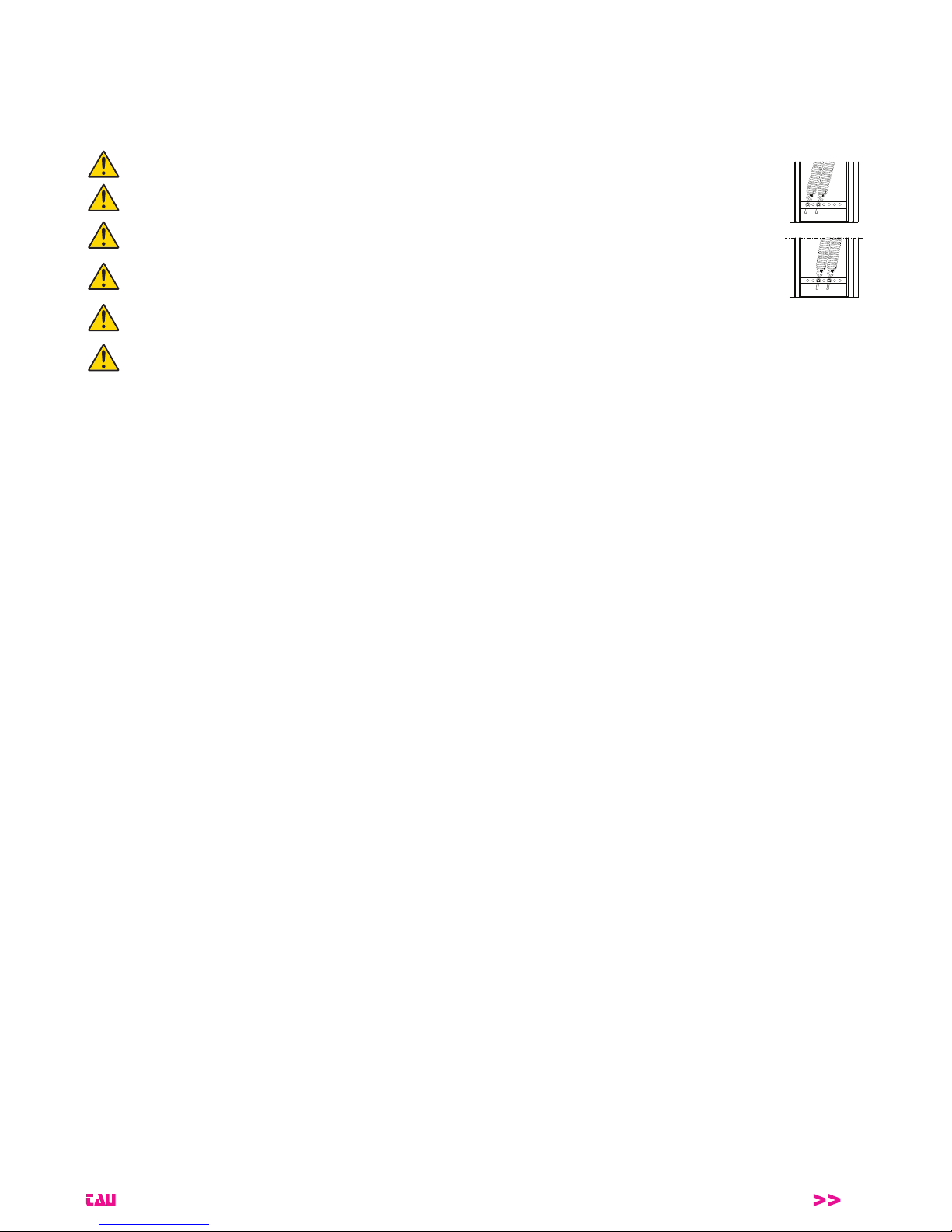
1 La molla più robusta deve sempre essere installata dal lato passo carraio (1 g. 6) - The strongest spring should always be in-
stalled on the boom’s side (1 - pic. #6) - Die härtere Ausgleichsfeder muss neben den Schrankenbaum montiert werden (1 - Abb.
6) - Le ressort plus robuste doit être monté du côté de la lisse (1 - image 6) - El resorte más robusto tiene que ser puesto en el lado
del hasta (1 - imagen 6) - A mola mais forte deve ser instalada no lado da haste (1 - imagem 6).
2 La molla meno robusta deve sempre essere installata dal lato passo carraio (1 g. 6) - The weakest spring should always be installed
on the boom’s side (1 - pic. #6) - Die weniger harte Ausgleichsfeder muss neben den Schrankenbaum montiert werden (1 - Abb. 6) -
Le ressort moins robuste doit être monté du côté de la lisse (1 - image 6) - El resorte menos robusto tiene que ser puesto en el lado
del hasta (1 - imagen 6) - A mola menos forte deve ser instalada no lado da haste (1 - imagem 6).
*
ATTENZIONE: congurazione per asta da 4 a 5 m. 800AE5 non va assemblata con il giunto 800GI.
*ATTENTION: solution for boom lengths between 4 and 5 m - Do not assemble the boom 800AE5 with the joint 800GI.
*ACHTUNG: Konguration für Schrankenbaum von 4 bis 5 m. 800AE5 muss nicht mit dem 800GI Schrankenbaum-Verbindung zusammengebaut werden.
*ATTENTION: solution pour lisses de longueur entre 4 et 5 mètres. Ne pas assembler la lisse 800AE avec la jonction 800GI
*ATENCIÓN: conguración por asta de 4 a 5 m. 800AE5 no se debe ensamblar con la junta 800GI.
*ATENÇÃO: conguração para haste entre 4 a 5m. A haste 800AE5 não deve ser montada com a união 800GI.
Per lunghezze asta uguali o superiori a 5 m è obbligatorio l’uso dell’appoggio asta a terra sso o pensile.
For boom lengths equal or greater than 5 mt. it must use (mandatory) the ground boom support or the pendulum support
Bei einer Stangenlänge gleich oder über 5 m ist die Anwendung der Stangenauage am Boden fest oder hängend notwendig.
Pour lisses de 5 ou plus metrès de longueur, l’utilisation de la lyre de repos appui au sol ou suspendu est contraignante.
En el caso de que la longitud de la barra sea de 5 m o más, será obligatorio utilizar un soporte para la barra anclado al suelo o colgante.
Para comprimentos de haste iguais ou superiores a 5 m deve-se utilizar o suporte para haste xo no chão ou suspenso.
Per aste con passaggi utili superiori a 5 m è OBBLIGATORIO usare il rinforzo 800RA.
For bars with useful passage exceeding 5m, it is COMPULSORY to use the 800RA reinforcement.
Für Stangen mit Nenndurchlass über 5 m ist eine Verstärkung von 800RA UNBEDINGT notwendig.
Pour les barres de plus de 5 m d’envergure il est OBLIGATOIRE d’utiliser le renforcement 800RA.
Para varillas con pasaje útil superior a 5 m es OBLIGATORIO usar el refuerzo 800RA.
Para haste com largura de passagem útil superior a 5m é OBRIGATÓRIO aplicar o reforço 800RA.
LUXE
5
ATTENZIONE: RISPETTO ALLA LUNGHEZZA NOMINALE DELL’ASTA, IL PASSAGGIO UTILE SI RIDUCE DI 353 mm (vedi g. 1).
ATTENTION: PASSAGE WIDTH EQUALS BAR LENGTH LESS 353 mm (see pic. #1).
ACHTUNG: TATSÄCHLICHE ABSPERRBREITE IST GLEICH BAUMLAENGE MINUS 353 mm (siehe Abb. 1).
AVERTISSEMENT: LE PASSAGE UTILE EST RÉDUIT DE 353 mm PAR RAPPORT À LA LONGUEUR NOMINALE DE LA LISSE (voir g. 1).
ATENCIÓN: EL PASO LIBRE ES IGUAL A LA LONGITUD DEL ASTA MENOS 353 mm (véase g. 1).
ATENÇÃO: A PASSAGEM UTIL É IGUAL AO CUMPRIMENTO DO HASTE MENOS 353 mm (ver g. 1).
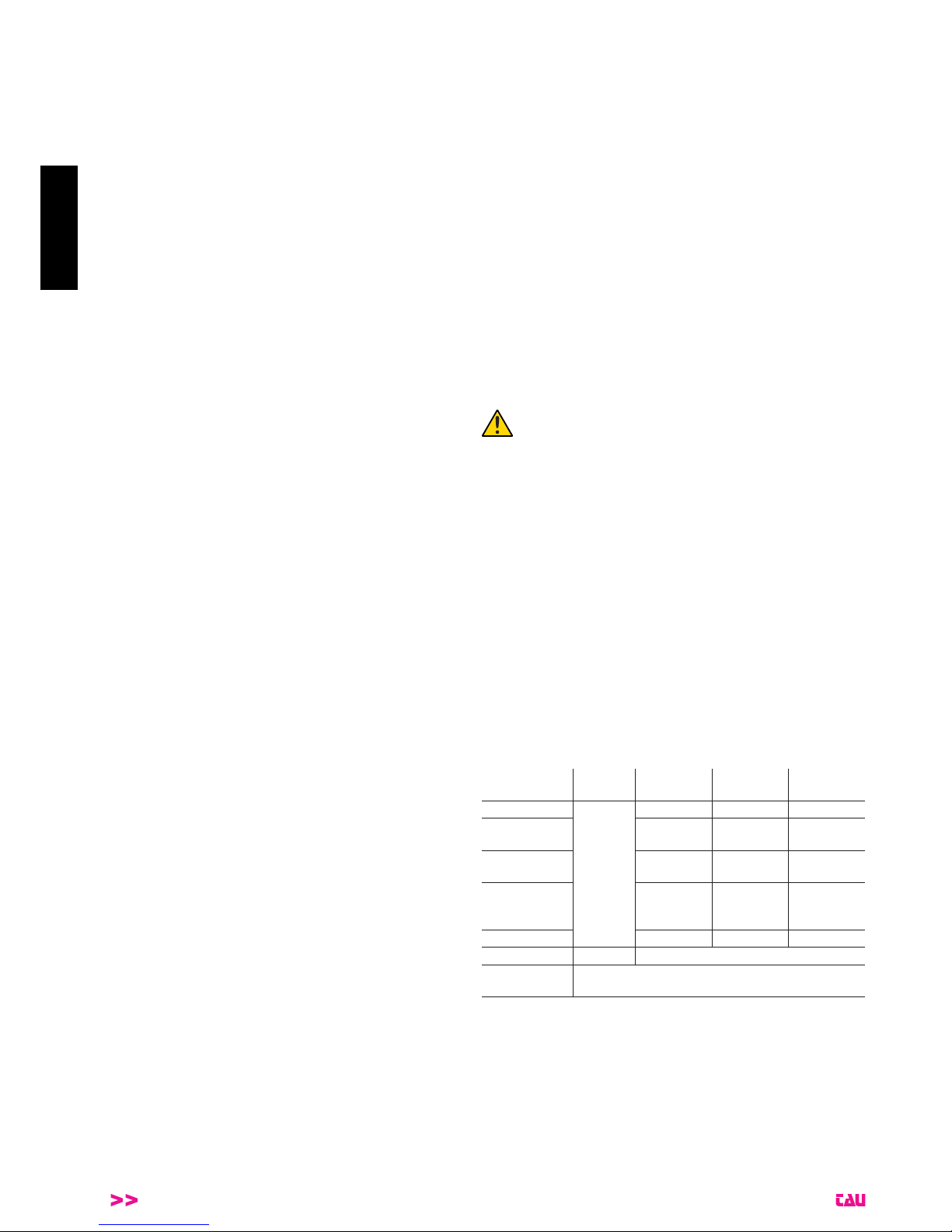
La trave forata permette di determinare carichi massimi differenti (in relazione alla lunghezza dell’asta e degli
accessori applicati ad essa) nelle varie posizioni (più ci si avvicina alla verticale, minore è il carico massimo).
MAX. LOAD
MIN. LOAD
The drilled beam allows to determine different maximum loads (in relation to the length of the bar and acces-
sories applied) in the various positions (the nearer to the vertical, the lower the maximum load).
Der gebohrte Träger gestattet die festlegung anderer max. Lasten (in Abhängigkeit von der Länge der Stange
sowie dem angebrachten Zubehör) in verschiedenen Positionen (je näher der vertikalen, desto geringer ist die
max. Last).
Le faisceau perforé permet de déterminer les différentes charges maximales (par rapport à la longueur de la
barre et des accessoires qui lui sont appliqués) dans les différentes positions (plus on se rapproche de la ver-
ticale, plus la charge maximale diminue).
El travesaño perforado permite determinar cargas máximas diferentes (con relación a la longitud del asta y de
los accesorios aplicados en ella) en las distintas posiciones (más se acerca a la vertical menor será la carga
máxima).
O feixe de perfuração permite detreminar a carga máxima (em relação ao comprimento da haste e acessórios
aplicados) em várias posições (mais próximo do vertical, carga máxima menor).

LUXE
6
DICHIARAZIONE DI INCORPORAZIONE DEL COSTRUTTORE
(ai sensi della Direttiva Europea 2006/42/CE AlI. II.B)
Fabbricante: TAU S.r.l.
Indirizzo: Via E. Fermi, 43
36066 Sandrigo (Vi)
ITALIA
Dichiara sotto la propria responsabilità che il prodotto: Attuatore elettromeccanico
realizzato per il movimento automatico di: Barriere stradali
per uso in ambiente: Generico
completo di: Centrale elettronica di controllo e radioricevente
Modello: LUXE
Tipo: LUXE - LUXE/I
Numero di serie: VEDI ETICHETTA ARGENTATA
Denominazione commerciale: BARRIERA AUTOMATICA
È realizzato per essere incorporato su una chiusura (barriera automatica) o per essere assemblato con altri dispositivi al ne di movi-
mentare una tale chiusura per costituire una macchine ai sensi della Direttiva Macchine 2006/42/CE.
Dichiara inoltre che questo prodotto è conforme ai requisiti essenziali di sicurezza delle seguenti ulteriori direttive CEE:
- 2014/35/EU Direttiva Bassa Tensione
- 2014/30/EU Direttiva Compatibilità Elettromagnetica
ed, ove richiesto, alla Direttiva:
- 2014/53/EU Apparecchiature Radio e apparecchiature terminali di telecomunicazione
Dichiara inoltre che non è consentito mettere in servizio il macchinario no a che la macchina in cui sarà incorporato o di cui diverrà
componente sia stata identicata e ne sia stata dichiarata la conformità alle condizioni della Direttiva 2006/42/CE.
Sono applicate le seguenti norme e speciche tecniche:
EN 61000-6-2; EN 61000-6-3; EN 60335-1; ETSI EN 301 489-1 V1.9.2; ETSI EN 301 489-3 V1.6.1;
EN 300 220-2 V2.4.1; EN 12453:2000; EN 12445:2000; EN 60335-2-103
Si impegna a trasmettere, su richiesta adeguatamente motivata delle autorità nazionali, informazioni pertinenti sulle quasi-macchine.
Sandrigo, 12/09/2017
Il Rappresentante Legale
_________________________________________
Loris Virgilio Danieli
Nome e indirizzo della persona autorizzata a costituire la documentazione tecnica pertinente:
Loris Virgilio Danieli - via E. Fermi, 43 - 3606 Sandrigo (Vi) Italia
ITALIANO

LUXE
7
ITALIANO
AVVERTENZE PER L’INSTALLATORE
OBBLIGHI GENERALI PER LA SICUREZZA
1) Leggere attentamente le istruzioni prima di procedere
all’installazione, in quanto forniscono importanti indica-
zioni concernenti la sicurezza, l’installazione, l’uso e la
manutenzione. Una errata installazione o un errato uso
del prodotto può portare a gravi danni alle persone.
2) I materiali dell’imballaggio (plastica, polistirolo, ecc.) non de-
vono essere lasciati alla portata dei bambini in quanto poten-
ziali fonti di pericolo.
3) Conservare le istruzioni per riferimenti futuri.
4) Questo prodotto è stato progettato e costruito esclusivamen-
te per l’utilizzo indicato in questa documentazione. Qualsiasi
altro utilizzo non espressamente indicato potrebbe pregiudi-
care l’integrità del prodotto e/o rappresentare fonte di perico-
lo.
5) TAU Srl declina qualsiasi responsabilità derivata dall’uso im-
proprio o diverso da quello per cui l’automatismo è destinato.
6) Non installare l’apparecchio in atmosfera esplosiva: la pre-
senza di gas o fumi inammabili costituisce un grave pericolo
per la sicurezza.
7) Gli elementi costruttivi meccanici devono essere in accordo
con quanto stabilito dalle Norme EN 12604 e EN 12605. Per
i Paesi extra-CEE, oltre ai riferimenti normativi nazionali, per
ottenere un livello di sicurezza adeguato, devono essere se-
guite le Norme sopra riportate.
8) TAU Srl non è responsabile dell’inosservanza della Buona
Tecnica nella costruzione delle chiusure da motorizzare, non-
ché delle deformazioni che dovessero intervenire nell’utiliz-
zo.
9) L’installazione deve essere effettuata nell’osservanza delle
Norme EN 12453 e EN 12445. Per i Paesi extra-CEE, oltre
ai riferimenti normativi nazionali, per ottenere un livello di si-
curezza adeguato, devono essere seguite le Norme sopra
riportate.
10) Prima di effettuare qualsiasi intervento sull’impianto, togliere
l’alimentazione elettrica.
11) Prevedere sulla rete di alimentazione dell’automazione un
interruttore onnipolare con distanza d’apertura dei contatti
uguale o superiore a 3 mm. È consigliabile l’uso di un ma-
gnetotermico da 6A con interruzione onnipolare.
12) Vericare che a monte dell’impianto vi sia un interruttore dif-
ferenziale con soglia da 0,03 A.
13) Vericare che l’impianto di terra sia realizzato a regola d’arte
e collegarvi le parti metalliche della chiusura.
14) L’automazione dispone di una sicurezza intrinseca anti-
schiacciamento costituita da un controllo di coppia. E’ co-
munque necessario vericarne la soglia di intervento secon-
do quanto previsto dalle Norme indicate al punto 9.
15) I dispositivi di sicurezza (norma EN 12978) permettono di
proteggere eventuali aree di pericolo da Rischi meccanici di
movimento, come ad Es. schiacciamento, convogliamento,
cesoiamento.
16) Per ogni impianto è consigliato l’utilizzo di almeno una se-
gnalazione luminosa (900T-LED, 800LA, 800LL) nonché di
un cartello di segnalazione ssato adeguatamente sulla strut-
tura dell’insso, oltre ai dispositivi citati al punto 15.
17) TAU Srl declina ogni responsabilità ai ni della sicurezza e
del buon funzionamento dell’automazione, in caso vengano
utilizzati componenti dell’impianto non di produzione TAU.
18) Per la manutenzione utilizzare esclusivamente parti originali
TAU.
19) Non eseguire alcuna modica sui componenti facenti parte
del sistema d’automazione.
20) L’installatore deve fornire tutte le informazioni relative al
funzionamento manuale del sistema in caso di emergenza
e consegnare all’Utente utilizzatore dell’impianto la “Guida
Utente” allegata al prodotto.
21) Non permettere ai bambini o persone di sostare nelle vicinan-
ze del prodotto durante il funzionamento.
22) Tenere fuori dalla portata dei bambini radiocomandi o qual-
siasi altro datore di impulso, per evitare che l’automazione
possa essere azionata involontariamente.
23) Il transito deve avvenire solo ad automazione ferma.
24) L’Utente utilizzatore deve astenersi da qualsiasi tentativo di
riparazione o d’intervento diretto e rivolgersi solo a personale
qualicato.
25) Non lavare l’automazione con idropulitrice.
26) Manutenzione: effettuare almeno semestralmente la verica
funzionale dell’impianto, con particolare attenzione all’ef-
cienza dei dispositivi di sicurezza (compresa, ove previsto, la
forza di spinta dell’operatore) e di sblocco.
27) Tutto quello che non è previsto espressamente in queste
istruzioni non è permesso.
1_ CONDIZIONI DI UTILIZZO
La barriera automatica LUXE è stata progettata per l’utilizzo in
parcheggi privati o pubblici, in aree residenziali o in zone ad alta
intensità di passaggio.
2_ MISURE DI INGOMBRO
Nella g. 1 sono indicate le principali misure di ingombro per la
barriera; in g. 2 sono riportate le dimensioni della contropiastra
di fondazione.
3_ INSTALLAZIONE
L’installazione deve essere effettuata da personale
qualicato ed esperto e nel pieno rispetto delle norma-
tive vigenti.
3.1_ Veriche preliminari
Per la sicurezza e per un corretto funzionamento dell’automazione,
vericare l’esistenza dei seguenti requisiti:
• La sbarra nel suo movimento non deve assolutamente incon-
trare ostacoli o cavi aerei di tensione.
• Le caratteristiche del terreno devono garantire una sufciente
tenuta del plinto di fondazione.
• Prevedere adeguato dispositivo di disconnesione onnipolare,
con distanza maggiore di 3 mm tra i contatti, a sezionamento
dell’alimentazione;
• Nella zona di scavo del plinto non devono essere presenti tu-
bazioni o cavi elettrici.
• Se il corpo barriera si trova esposto al passaggio di veicoli,
possibilmente prevedere adeguate protezioni contro urti acci-
dentali.
• Vericare l’esistenza di una efciente presa di terra per il colle-
gamento dell’armadio.
• Predisporre adeguate tubazioni e canaline per il passaggio dei
cavi elettrici garantendone la protezione contro il danneggia-
mento meccanico.
3.2_ Tipologia cavi
Collegamento Tipologia
cavo
L cavo
1 < 10 m
L cavo
10 < 20 m
L cavo
20 < 30 m
Alimentazione
230 V
FROR
CEI 20-22
CEI EN
50267-2-1
3 x 1,5 mm² 3 x 2,5 mm² 3 x 4 mm²
Trasmettitori
fotocellule 2 x 0,5 mm² 2 x 0,5 mm² -
Ricevitori
fotocellule 4 x 0,5 mm² 4 x 0,5 mm² -
Alimentazione
accessori 24 V 2 x 0,5 mm² 2 x 1 mm² -
Dispositivi di
comando 2 x 0,5 mm² 2 x 0,5 mm² 2 x 0,5 mm²
Antenna RG58 cavo fornito in dotazione
Rilevatore mas-
se metalliche vedi istruzioni relative
NOTA: Qualora i cavi abbiano lunghezza diversa rispetto a
quanto previsto in tabella, si determini la sezione dei cavi
sulla base dell’effettivo assorbimento dei dispositivi collega-
ti e secondo le prescrizioni indicate dalla normativa CEI EN
60204-1.
Per i collegamenti che prevedano più carichi sulla stessa li-
nea (sequenziali), il dimensionamento a tabella deve essere
riconsiderato sulla base degli assorbimenti e delle distanze
effettivi. Per i collegamenti di prodotti non contemplati in que-
sto manuale fa fede la documentazione allegata ai prodotti
stessi.

LUXE
8
3.3_ Impianto tipo (g. 11)
1 Armadio Luxe
2 Quadro di comando
3 Asta in alluminio
4 Striscia led
5 Giunto per asta
6 Indicatore luminoso a led
7 Antenna
8 Colonnina per fotocellule
9 Fotocellule
10 Supporto laterale per fotocellula
11 Appoggio asta (sso)
12 Rilevatore masse metalliche
3.4_ Preparazione base automazione
Murare la piastra di fondazione in modo da permettere
un agevole accesso allo sportello della barriera ed alla
maniglia di sblocco.
Creare una soletta (A g. 3) di forma rettangolare e di adeguate
dimensioni prevedendo i fori per l’uscita dei cavi. Usare possibil-
mente la contropiastra di fondazione (B g. 3), con i 4 tiranti in do-
tazione da annegare nel cemento; oppure, a soletta nita, ssare
l’armadio della barriera direttamente con 4 tasselli da fondazione
M10x120 (C g. 3). Lo spessore della soletta deve essere di alme-
no 10 cm, ricordando che può essere aumentato se le condizioni
del terreno lo richiedono.
3.5_ Installazione del gruppo barriera
La barriera priva di asta e di molle va ora posizionata procedendo
come descritto di seguito:
- togliere dadi e rondelle dalle viti sporgenti, posizionare l’ar-
madio sulla base e ssarlo. Si controlli ora l’assoluta stabilità
dell’ancoraggio e si operi, se necessario, in tal senso.
Nota: è consigliabile installare l’armadio con la porta rivolta verso
il lato più agevole.
- Aprire la porta con l’apposita chiave e rimuoverla.
Normalmente “LUXE” viene consegnata DESTRA (DX), con il por-
ta asta in posizione orizzontale. Per barriera destra (DX) si intende
con l’armadio posizionato a destra visto dall’interno del passaggio
(convenzionalmente, lo sportello va all’interno).Se ci dovesse es-
sere l’esigenza di trasformarla SINISTRA (SX), occorre invertire il
senso di apertura dell’asta.
Operare come segue:
1_ dopo aver rimosso le viti con occhiello e gli anelli elastici,
estrarre i perni e riposizionarli, simmetricamente, dal lato op-
posto della trave forata (g. 4A), quindi fermarli con gli anelli
elastici e riavvitare le viti;
2_ dopo aver asportato la vite e la rondella di bloccaggio, rimuove-
re la leva di bilanciamento asta. Nel gruppo di sostegno molle,
invertire la posizione del perno (1 g. 4B), quindi ruotare tutto
il blocco di 180° (rispetto alla posizione precedente) e ssarlo
nuovamente all’albero motore con bullone e rondella (g. 4C);
3_ una volta modicato il senso della barriera è necessario inver-
tire i collegamenti del motore (vedi istruzioni K206MA).
La trave forata permette di determinare carichi massimi
differenti (in relazione alla lunghezza dell’asta e degli
accessori applicati ad essa) nelle varie posizioni (più ci
si avvicina alla verticale, minore è il carico massimo).
Una volta modicato il senso della barriera, la colloca-
zione dei dispositivi è invertita.
Nel caso si debba modicare la barriera da SX a DX, le operazioni
da eseguire sono le stesse.
3.6_ Fissaggio asta, montaggio molle e bilanciamento asta
Ogni operazione va eseguita in assenza di alimentazione.
Dopo aver sbloccato l’automazione (vedi capitolo “Sblocco ma-
nuale”), operare come segue:
1_ servendosi di un appoggio, avvicinare l’asta in orizzontale (to-
talmente assemblata con tutti gli accessori previsti) al porta
asta e ssarla con la staffa ad omega, per mezzo delle viti in
dotazione (g. 5A);
Nota: l’asta deve essere inserita per tutta la lunghezza della
staffa ad omega.
2_ una volta ssata la staffa ad omega passare, se presente, il
cavo dei led (dopo aver tolto il tappo di protezione) attraverso
il foro predisposto sull’armadio (fare riferimento alla gura 9
per portare il cavo alla centrale di comando), quindi montare la
copertura e ssarla con le viti in dotazione (g. 5B);
3_ portare ora l’asta in posizione verticale e bloccare il motoridut-
tore (vedi capitolo “Sblocco manuale”).
Procedere quindi al montaggio delle molle agganciadole alle viti
con occhiello e ruotarle manualmente nel senso indicato dalla frec-
cia per eseguire un primo precarico (g. 5C).
Procedere ora con il bilanciamento dell’asta.
Prima di bilanciare l’asta, vericare, con la tabella di pag.
4, la congruenza tra molla scelta, accessori da applicare
e luce passaggio. Il corretto bilanciamento è fondamen-
tale per un buon funzionamento della barriera.
Questa operazione va eseguita solo quando l’asta è montata
in modo denitivo e con tutti gli eventuali accessori.
g. 6: agire sullo sblocco manuale (vedi capitolo “Sblocco ma-
nuale”) mantenendo una distanza di sicurezza. L’asta deve
portarsi da sola a 30°, altrimenti caricare/scaricare le molle
(se l’asta tende ad alzarsi oltre i 30° le molle vanno scarica-
te, ossia bisogna ruotarle manualmente in senso antiorario,
viceversa, se non raggiunge i 30°, le molle vanno caricate,
ossia ruotate manualmente in senso orario). Abbassare l’a-
sta e rilasciarla, controllare che abbia raggiunto i 30°.
Per un buon funzionamento della barriera, all’atto del
carico/scarico delle molle, mantenere la stessa spor-
genza delle viti con occhiello (g. 5C).
Procedere con i collegamenti elettrici al quadro comando (vedi ca-
pitolo collegamenti elettrici).
Nota: vericare il corretto funzionamento della molla.
ATTENZIONE! Per un corretto funzionamento, con asta
completamentamente aperta le molle devono sempre
mantenere un minimo di carico.
3.7_ Sblocco manuale
ATTENZIONE! Lo sblocco e qualsiasi altra operazione
manuale vanno eseguite solo con asta montata. Si fa
assoluto divieto di azionare la barriera priva di asta.
1_ Inserire la chiave nella serratura della maniglia sul retro dell’ar-
madio e ruotarla di 180° in senso antiorario (g. 7A);
2_ estrarre la maniglia e ruotarla di 90° in senso antiorario no a
sbloccare l’asta (se inizialmente sembra resistere, imprimere
alla maniglia maggior forza, non si provocano rotture di alcun
tipo), g. 7B.
A sblocco avvenuto, l’asta deve automaticamente portarsi
nella posizione di equilibrio (30° ca.).
ATTENZIONE! L’operazione di sblocco può rappresen-
tare un possibile pericolo per l’utente quando, per un
qualsiasi motivo (asta mal ssata alla sua sede durante
il montaggio, asta divelta o spezzata da un incidente
etc.) le molle in tensione non garantiscono più il bilan-
ciamento!
Esse possono provocare perciò una brusca rotazione
dell’attacco asta e/o dell’asta stessa.
3.8_ Regolazione dei necorsa
Normalmente la barriera viene fornita con i necorsa già regolati
per permettere il movimento ideale dell’asta.
In caso di errato livellamento della piastra da cementare, I’asta
potrebbe non risultare perfettamente orizzontale o verticale con un
conseguente cattivo risultato estetico dell’installazione.
Per eventualmente correggere la posizione verticale (=apertura),
chiudere la sbarra, aprire la porta e ruotare il tampone libero (1 g.
8) in senso orario (per aumentare la corsa dell’asta) o antiorario
(per diminuire la corsa dell’asta).
ITALIANO

LUXE
9
Analogamente, per correggere la posizione orizzontale (= chiusu-
ra), aprire la sbarra e regolare il tampone libero (2 g. 8).
Dopo le veriche o le regolazioni di apertura e chiusura dell’asta,
serrare denitivamente i controdadi di ssaggio sotto i tamponi.
Ogni qualvolta viene modicata la posizione dei ne-
corsa meccanici, è necessario ripetere la procedura di
memorizzazione sulla scheda di comando (vedi istru-
zioni K206MA).
A regolazione ultimata, eseguire la procedura di memorizza-
zione sulla scheda di comando (vedi istruzioni K206MA), veri-
cando, dalla seconda manovra in automatico (la prima serve
alla centrale di comando per acquisire i nuovi necorsa) la
corretta posizione dell’asta, eventualmente ripetere la proce-
dura.
Al completamento di tutte le operazioni di installazione meccanica
ed elettronica ssare il coperchio dell’armadio, riposizionare la por-
ta e chiuderla con la chiave.
3.9_ Collegamenti elettrici
Ciascun dispositivo, alimentazione inclusa, deve essere installato
a regola d’arte e comunque secondo le normative vigenti. Sepa-
rare i cavi di potenza dai cavi di comando, specialmente se i per-
corsi sono lunghi (oltre 50 mt). Per la sezione dei cavi (antenna
esclusa), la TAU consiglia: alimentazione 1,5 mm², altri cavi 0,5
mm² e comunque di attenersi alla norma IEC 364 e alle norme di
installazione vigenti nel proprio Paese. Per accedere alla scheda
comando togliere il coperchio dell’armadio (1 g. 9) dopo aver ri-
mosso le viti di bloccaggio e le rondelle. Ora è possibile accedere
alle connessioni.
N.B. I cablaggi interni sono già effettuati e collaudati. Occorre
provvedere al collegamento dell’alimentazione, della fotocel-
lula esterna, dei led e di eventuali comandi remoti e alla pro-
grammazione della scheda.
3.10_ Ultime operazioni
Provata l’efcacia di ogni singolo dispositivo preposto al comando
o al controllo della barriera, assicurarsi del ripristino dell’integrità
della stessa prima di renderla al servizio degli utenti.
Sistemare quindi in un luogo di facile leggibilità cartelli indicanti la
presenza della barriera automatica.
4_ USO
La barriera é stata concepita solo ed unicamente per limitare il us-
so di veicoli e/o persone in accessi protetti tramite l’impedimento
esercitato dall’asta. In caso di mancanza di alimentazione, è previ-
sto, a richiesta, il funzionamento con batteria a secco 12V.
Si ricorda inoltre che si è in presenza di un apparecchio elettrico, e
come tale va avvicinato e usato con circospezione e prudenza. In
particolare raccomandiamo di:
• non toccare l’apparecchio con mani bagnate e/o piedi nudi o bagnati;
• non consentire il funzionamento automatico o semiautomatico
in presenza di malfunzionamenti certi o sospetti;
• non tirare il cavo di alimentazione per scollegare l’apparecchio;
• non lasciare che bambini o incapaci dispongano delle chiavi dell’ar-
madio e dei comandi (anche via radio) anche se solo per diletto;
• non comandare la barriera quando non si ha la completa visibi-
lità della barriera stessa;
• non entrare nel raggio di azione della barriera mentre è in mo-
vimento, ma attenderne l’arresto;
• non appoggiarsi all’armadio o all’asta per nessun motivo, ne-
anche a barriera inattiva e comunque non sostare nel raggio di
azione della barriera;
• non lasciare che bambini o animali giochino nei pressi della
barriera;
• non adoperare la barriera per usi diversi da quello previsto (es.
sollevamento pesi o persone). Il costruttore non assumerà al-
cuna responsabilità per danni derivanti da tali comportamenti;
• provvedere alla manutenzione periodica da parte di personale
specializzato;
• in caso di guasto togliere l’alimentazione. Procedere alla ge-
stione manuale solo se sicura. Astenersi dall’intervenire e rivol-
gersi esclusivamente a personale qualicato della casa madre
o da essa autorizzato. Assicurarsi in ogni caso che i pezzi di
ricambio siano originali per non compromettere la sicurezza
della barriera.
5_ MANUTENZIONE
Da effettuare solamente da parte di personale specializzato dopo
aver tolto I’alimentazione elettrica al motore.
Ogni 100.000 manovre complete vericare:
- l’ingrassaggio delle molle;
- il bilanciamento dell’asta (vedi capitolo “Fissaggio asta, mon-
taggio molle e bilanciamento asta”);
- l’efcienza delle forze;
- lo stato della batteria, se presente;
- l’efcienza dei dispositivi di protezione e di sicurezza;
- I’usura delle battute di fermo meccanico e la regolazione dei
necorsa (vedi capitolo “Regolazione necorsa”).
La manutenzione sopra descritta è vitale per II corretto funzio-
namento del prodotto nel tempo.
Generalita’
La barriera non deve poter essere comandata da terzi durante
questa fase; togliere quindi l’alimentazione di rete (e la batteria se
presente).
• Sbloccare prima l’asta per agevolare l’operazione.
Ingrassaggio
1_ Aprire la porta della barriera;
2_ Dare grasso agli occhielli delle viti delle molle di bilanciamento (1
g. 10) e allo snodo sferico sulla leva di bilanciamento (3 g. 10);
3_ Ingrassare il punto di contatto tra l’eccentrico dello sblocco ma-
nuale e la leva di sblocco (2 g. 10).
4_ Tenersi lontani da ingranaggi o da parti meccaniche di possibi-
le movimento.
FREQUENZA: ogni 100.000 manovre o 6 mesi, pena la deca-
denza della garanzia.
N.B.: Si raccomanda esclusivamente l’impiego di grasso al
sapone di calcio complesso per alti carichi.
Bilanciamento asta
Controllare il bilanciamento dell’asta ripetendo le manovre descrit-
te nella sezione “Fissaggio asta, montaggio molle e bilanciamen-
to”. Tale operazione è basilare per il corretto funzionamento e la
durata della barriera. Se necessario, aumentare il precarico molle
per compensare l’usura della stessa. Nel caso in cui si renda ne-
cessaria la sostituzione delle molle, si veda più avanti il paragrafo
“Manutenzione straordinaria e riparazioni”.
FREQUENZA: ogni 100.000 manovre o 6 mesi, pena la decaden-
za della garanzia.
Controllo efcienza limitazione delle forze
Vericare la corrispondenza tra comportamento reale e comporta-
mento stabilito in fase di installazione.
FREQUENZA: ogni 100.000 manovre o 6 mesi, pena la decaden-
za della garanzia.
Controllo della batteria 12v cc
Utilizzando il tester per le batterie vericare il grado di carica della
batteria. In caso di sostituzione, rimpiazzare l’unità inutilizzabile
con una originale avendo cura di non abbandonarla nell’ambiente.
FREQUENZA: ogni 100.000 manovre o 6 mesi, pena la decaden-
za della garanzia.
Controllo dei dispositivi di protezione e di sicurezza rimanenti
Fotocellule: possono agire sia in apertura che in chiusura; control-
lare la programmazione del dip switch. Pulire l’involucro esterno.
Vericare che le seguenti speciche siano rispettate:
• Il lampeggiante sia funzionante e ben visibile.
• L’adesivo di segnalazione pericolo ssato sulla porta sia ben
attaccato e visibile.
• L’adesivo di segnalazione pericolo ssato nella parte dietro
della barriera sia ben attaccato e visibile. In caso di mancata
rispondenza di tali dispositivi ai criteri esposti, ripristinare la ori-
ginaria efcienza o, se impossibile, operare una loro sostituzio-
ne.
FREQUENZA: ogni 6 mesi, pena la decadenza della garanzia.
ITALIANO

LUXE
10
6_ MANUTENZIONE STRAORDINARIA E RIPARAZIONI
ATTENZIONE: DOPO LE PRIME 2000 MANOVRE ESEGUIRE
UNA NUOVA PROCEDURA DI BILANCIAMENTO DELL’ASTA.
Nel caso in cui si renda necessaria una riparazione di non banale
esecuzione o una sostituzione di pezzi di organi elettromeccanici,
si raccomanda la rimozione del blocco in cui l’operazione è loca-
lizzabile (scheda di comando, blocco del motoriduttore) per poter
cosi permettere una riparazione in ofcina dalla casa madre o da
tecnici da essa autorizzati. Diversamente, la sicurezza e l’afda-
bilità della barriera possono venir meno (cosi come il contratto di
garanzia).
In caso di utilizzo della barriera in ambiente salso o for-
temente contaminato da reagenti chimici corrosivi, la
frequenza dei controlli manutentivi si intende aumen-
tata in ragione dell’incrementato logorio ambientale; in
questo caso si raccomanda anche un’ispezione all’in-
tegrità dell’armadio esterno metallico.
7_ DIAGNOSI DELLE CAUSE DI GUASTO PIÙ COMUNE
In questo paragrafo verranno brevemente trattare le cause più pro-
babili dei guasti più comuni, in modo da favorire il pronto recupero
della barriera.
La casistica riportata non è in ogni caso completa (sia dal punto di
vista delle cause, che dal punto di vista dei guasti).
a_ La barriera è bloccata (aperta, chiusa o semiaperta):
1_ mancanza di alimentazione;
2_ comandi non efcienti;
3_ fusibile di alimentazione bruciato;
4_ fotocellule (abilitate anche in apertura) attive perché non alline-
ate e/o perché ostacolate (erba, ecc);
b_ la barriera continua ad aprirsi e chiudersi;
1_ controllare falsi contatti dei pulsanti dei telecomandi e dei selet-
tori a chiave che restano inseriti;
c_ la barriera resta aperta;
1_ le fotocellule sono attive perchè non allineate e/o perché spor-
che (fango,ecc) e/o ostacolate (erba, ecc);
d_ la barriera fatica ad aprirsi;
1_ la molla di bilanciamento asta è starata;
e_ la barriera si alza/abbassa più del limite previsto;
1_ i necorsa meccanici sono da registrare (vedi capitolo “REGO-
LAZIONE FINECORSA”).
8_ DISMISSIONE
Quando la barriera giunge alla ne del proprio servizio si consiglia
di rimuoverla per poi riciclarne i materiali riutilizzabili. Prestare at-
tenzione a quanto sancito da regolamenti e leggi locali e/o nazio-
nali. Si prega di porre attenzione al riciclo dei seguenti componenti:
• armadio verniciato con vernice epossidica
• cupolino lampeggiante in metacrilato
• scatola scheda comando in ABS
• schede elettroniche
• batteria 12V cc a secco (piombo acido)
• grasso al litio interno al riduttore
• connessioni e protezioni minori in gomma e/o plastica.
RISPETTARE L’AMBIENTE!
AVERTENZE PER LO SMONTAGGIO: le operazioni di rimozione
della barriera devono rispettare criteri di sicurezza: disconnettere
quindi per prima cosa la barriera dalle rete elettrica. Allentare (non
completamente) i tiranti di regolazione delle molle di bilanciamento
per poter togliere l’asta più comodamente e con maggior tranquil-
lità. Svitare quindi le viti di ancoraggio sul fondo dell’armadio per
poterlo maneggiare a piacimento.
9_ TRASPORTO
La barriera è imballata in uno scatolone di cartone separatamente
all’asta, che può essere acquistata su richiesta.
Si raccomanda cura e perizia in ogni fase di movimentazione. Per il
sollevamento e lo spostamento si consiglia l’uso di carrelli manuali
o motorizzati. Lo stoccaggio, anche temporaneo, deve avvenire
verticalmente rispettando il verso indicato sull’imballo e tenendo
presente che il baricentro alto conferisce instabilità.
L’asta deve essere stoccata avendo cura di evitare sporgenze o
carichi che possano danneggiarla. Una volta privati dell’imballo
assicurarsi dell’integrità del prodotto. Non abbandonare gli imballi,
bensì riciclarli secondo le normative vigenti nel paese di impiego.
ATTENZIONE: non lasciare che i bambini maneggino
i materiali di imballo per evitare soffocamenti e altri
pericoli di sorta.
GARANZIA: CONDIZIONI GENERALI
La garanzia della TAU ha durata di 24 mesi dalla data di acquisto
dei prodotti (fa fede il documento scale di vendita, scontrino o
fattura).
La garanzia comprende la riparazione con sostituzione gratuita
(franco sede TAU: spese di imballo e di trasporto sono a carico
del cliente) delle parti che presentano difetti di lavorazione o vizi di
materiale riconosciuti dalla TAU.
In caso di intervento a domicilio, anche nel periodo coperto da ga-
ranzia, l’utente è tenuto a corrispondere il “Diritto sso di chiamata”
per spese di trasferimento a domicilio, più manodopera.
La garanzia decade nei seguenti casi:
• Qualora il guasto sia determinato da un impianto non es-
eguito secondo le istruzioni fornite dall’azienda all’interno
di ogni confezione.
• Qualora non siano stati impiegati tutti componenti originali
TAU per l’installazione dell’automatismo.
• Qualora i danni siano causati da calamità naturali, man-
omissioni, sovraccarico di tensione, alimentazione non
corretta, riparazioni improprie, errata installazione, o altre
cause non imputabili alla TAU.
• Qualora non siano state effettuate le manutenzioni periodi-
che da parte di un tecnico specializzato secondo le istruzi-
oni fornite dall’azienda all’interno di ogni confezione.
• Usura dei componenti.
La riparazione o la sostituzione dei pezzi durante il periodo di ga-
ranzia non comporta un prolungamento del termine di scadenza
della garanzia stessa.
In caso di utilizzo industriale o professionale oppure in caso di im-
piego simile, tale garanzia ha validità 12 mesi.
ITALIANO

LUXE
11
MANUFACTURER’S DECLARATION OF INCORPORATION
(in accordance with European Directive 2006/42/EC App. II.B)
Manufacturer: TAU S.r.l.
Address: Via E. Fermi, 43
36066 Sandrigo (Vi)
ITALY
Declares under its sole responsibility, that the product: Electromechanical actuator
designed for automatic movement of: Road Barriers
for use in a: General environment
complete with: Electronic control unit and radioreceiver
Model: LUXE
Type: LUXE - LUXE/I
Serial number: SEE SILVER LABEL
Commercial name: AUTOMATIC BARRIER
Has been produced for incorporation on an access point (automatic barrier) of for assembly with other devices used to move such an
access point, to constitute a machine in accordance with the Machinery Directive 2006/42/EC.
Also declares that this product complies with the essential safety requirements of the following EEC directives:
- 2014/35/EU Low Voltage Directive
- 2014/30/EU Electromagnetic Compatibility Directive
and, where required, with the Directive:
- 2014/53/EU Radio equipment and telecommunications terminal equipment
Also declares that it is not permitted to start up the machine until the machine in which it is incorporated or of which it will be a com-
ponent has been identied with the relative declaration of conformity with the provisions of Directive 2006/42/EC.
The following standards and technical specications are applied:
EN 61000-6-2; EN 61000-6-3; EN 60335-1; ETSI EN 301 489-1 V1.9.2; ETSI EN 301 489-3 V1.6.1;
EN 300 220-2 V2.4.1; EN 12453:2000; EN 12445:2000; EN 60335-2-103.
The manufacturer undertakes to provide, on sufciently motivated request by national authorities, all information pertinent to the quasi-
machinery.
Sandrigo, 12/09/2017
Legal Representative
_________________________________________
Loris Virgilio Danieli
Name and address of person authorised to draw up all pertinent technical documentation:
Loris Virgilio Danieli - via E. Fermi, 43 - 3606 Sandrigo (Vi) Italia
ENGLISH
LUXE
12
INSTALLATION WARNINGS
GENERAL SAFETY REQUIREMENTS
1) Carefully read all instructions before installation, as they
provide important instructions regarding the safety, in-
stallation, operation and maintenance. Incorrect instal-
lation or use of the product may lead to serious physical
injury.
2) Never leave packaging materials (plastic, polystyrene etc.)
within the reach of children as they constitute a potential haz-
ard.
3) Keep the instructions in a safe place for future consultation.
4) This product has been designed and constructed exclusively
for the use specied in this documentation. Any other use not
specied herein may impair product integrity and/or consti-
tute a hazard.
5) TAU Srl declines all liability for improper use or use other than
as specied for this automation.
6) Do not install the unit in an explosive environment: the pres-
ence of either gas or ammable fumes is a serious safety
risk.
7) The mechanical elements must comply with the requirements
as stated in the standards EN 12604 and EN 12605. For non
European member states, in addition to the national refer-
ence standards, the above-mentioned standards must be ob-
served to ensure an adequate level of safety.
8) TAU Srl is not responsible for failure to observe Good Prac-
tice in construction of the gates/doors to be power-operated,
nor any deformations occurring during use.
9) Installation must be performed in compliance with the stand-
ards EN 12453 and EN 12445. For non European member
states, in addition to the national reference standards, the
above-mentioned standards must be observed to ensure an
adequate level of safety.
10) Before performing any operations on the system, disconnect
from the mains and detach the batteries.
11) On the automation power line, install a device for disconnec-
tion from the power mains with a gap between contacts equal
to or greater than 3 mm. Use of a 6A thermal magnetic circuit
breaker with multi-pole switch is recommended.
12) Check upline of the system that there is a residual current
circuit breaker with a threshold of 0.03 A.
13) Ensure that the earthing system is to professional standards
and connected to the metal section of the gate/door.
14) The automation is equipped with an intrinsic anti-crushing
safety device comprising a torque control. The trip thresh-
old must in all cases be checked as stated in the standards
specied in point 9.
15) The safety devices (standard EN 12978) enable the protec-
tion of danger areas from risks associated with mechani-
cal movements such as crushing, dragging and shearing.
16) The use of at least one luminous indicator is recommended
for each system (900T-LED, 800LA, 800LL), as well as a
warning notice xed suitably to the frame structure, in addi-
tion to the devices specied in point 15.
17) TAU declines all liability for the safety and efcient operation
of the automation in the event of using system components
not produced by TAU.
18) For maintenance, use exclusively original TAU parts.
19) Never modify components that are part of the automation
system.
20) The installer must provide all information regarding manual
operation of the system in the event of an emergency and
supply the system User with the “User Guide” enclosed with
the product.
21) Never allow children or other persons to stay in the vicinity of
the product during operation.
22) Keep all radio controls or other pulse supplier device out of
the reach of children to prevent inadvertent activation of the
automation.
23) Transit should only occur with the automation stationary.
24) The user must never attempt to repair or intervene directly on
the product; always contact qualied personnel for assistance.
25) It is strictly forbidden to use high pressure water cleaners or
jets of water in general to clean the automation.
26) Maintenance: at least every six months, make a general
check of the system, with special reference to the efciency
of the safety devices (including, when envisaged, the opera-
tor thrust force) and release mechanisms.
27) All actions not expressly envisaged in these instructions
are strictly prohibited.
1_ CONDITIONS OF USE
The LUXE automatic barrier has been designed for use in private
or public car parks, residential areas or areas of intense trafc.
2_ OVERALL DIMENSIONS
The main dimensions of the barrier are indicated in pic. # 1; pic. #
2 illustrates the dimensions of the foundation base plate.
3_ INSTALLATION
Installation must be carried out by skilled and qualied
personnel in compliance with the regulations in force.
3.1_ Preliminary checks
For the safety and correct operation of the automation, check the
following:
• While moving the barrier must meet no obstacle or aerial power
cables.;
• The characteristics of the ground must guarantee sufcient
hold for the foundation plinth;
• A suitable omnipolar circuit breaker with a distance greater
than 3mm between contacts must be provided to isolate the
supply;
• There must be no pipes or electrical cables in the area where
the plinth foundation is excavated;
• If the barrier is exposed to passing vehicles, provide suitable
protection to avoid accidental collisions;
• Check there is an efcient earthing device to connect the cabi-
net;
• There must be suitable piping and tracks for electrical cables to
guarantee they are not damaged.
3.2_ Cables typology
Connection Type of
cable
Cable l.
1 < 10 m
Cable l.
10 < 20 m
Cable l.
20 < 30 m
230v supply
FROR
CEI 20-22
CEI EN
50267-2-1
3 x 1,5 mm² 3 x 2,5 mm² 3 x 4 mm²
Photocell trans-
mitters 2 x 0,5 mm² 2 x 0,5 mm² -
Photocell
receivers 4 x 0,5 mm² 4 x 0,5 mm² -
Accessory
24v power
supply
2 x 0,5 mm² 2 x 1 mm² -
Control devices 2 x 0,5 mm² 2 x 0,5 mm² 2 x 0,5 mm²
Aerial RG58 Cable supplied
Metal mass
sensor See relative instructions
NOTE: If the length of the cables is not as stated in the ta-
ble, determine the cable section on the basis of the real draw
of the connected devices and in compliance with the IEC EN
60204-1 Standard.
As to connections with numerous loads on the same line (in
sequence), dimensions must be recalculated on the basis of
the real draw and distance. As to the connection of any prod-
ucts not dealt with in this manual, the documents attached to
the products themselves must be consulted.
ENGLISH
LUXE
13
ENGLISH
3.3_ Typical system (pic. # 11)
1 Luxe cabinet
2 Control panel
3 Aluminium bar
4 LED strip
5 Bar gasket
6 LED display
7 Aerial
8 Photocell pillar
9 Photocells
10 Photocell side support
11 Bar rest (xed)
12 Metal mass sensor
3.4_ Automation base preparation
Wall the foundation plate so that the barrier door and
the releasing handle are easy to access.
Create a rectangular, suitably sized oor slab (A pic. # 3) with the
holes for the exiting cables. Use the foundation counterplate (B
pic. # 3), with the 4 anchors supplied to be buried in concrete; or,
once the oor slab is completed, x the cabinet to the barrier with
4 M10x120 foundation plugs (C pic. # 3). The slab thickness must
be at least 10cm and can be increased as required.
3.5_ Installation of the barrier group
Without bar and springs, the barrier must be positioned as follows:
- remove nuts and washers from the protruding bolts, position
the cabinet on the base and x it. Check it is anchored securely
and correct if necessary.
Note: it is advisable to install the cabinet with the door on the side
more easily accessible.
- Open the door with the relative key and remove.
LUXE is normally delivered RIGHT (RH), with the bar support in a
horizontal position. Right-hand barriers (RH) are barriers that have
the cabinet on the right-hand side viewed from the inside of the
passageway (the door is normally on the inside). If it is necessary
for it to be LEFT (LH), the opening must be inverted.
Proceed as follows:
1_ after removing the eye screws and the circlips, take the pins
and reposition them, symmetrically, on the opposite side of the
drilled beam (pic. # 4A), x with the circlips and screw the
screws in again;
2_ after removing the locking screw and washer, remove the bar
balancing lever. In the spring supporting group, invert the posi-
tion of the pin (1 pic. # 4B), rotate the whole block by 180° (in
respect of the previous position) and x the motor shaft again
with bolt and washer (pic. # 4C);
3_ once the opening direction has been modied, invert the motor
connections (see K206MA instructions).
The drilled beam allows to determine different maxi-
mum loads (in relation to the length of the bar and ac-
cessories applied) in the various positions (the nearer
to the vertical, the lower the maximum load).
Once the opening direction is modied, the positioning
of the devices must be inverted.
If the barrier must be modied from LH to RH, the operations are
the same.
3.6_ Bar xing, spring tting and bar balancing
All operations must be carried out with the power OFF.
After releasing the automation (see the “Manual release” chapter),
proceed as follows:
1_ using a support, bring the bar in the horizontal position (wholly
assembled and with all the accessories) near the bar support
and x with the omega bracket and the screws supplied (pic. #
5A);
Note: the bar must be inserted for the whole length of the ome-
ga bracket.
2_ when the omega bracket is xed, and after removing the pro-
tective cap, pass the LED cable through the hole on the cabinet
(to take the cable to the control unit, refer to gure 9) then t the
cover and secure it with the screws supplied (pic. # 5B);
3_ place the bar in a vertical position and block the gearmotor (see
the “Manual release” chapter).
Fit the springs hooking them to the eye screws and rotate manually
in the direction of the arrow for the rst preload (pic. # 5C).
Continue with bar balancing.
Before balancing the bar check on the table on page 4
the chosen spring, accessories to be applied and dis-
tance are adequate. Correct balancing is vital for the
barrier to work properly.
This operation must be carried out only when the bar has
been installed permanently with all its accessories.
pic. # 6: operate the manual release (see the “Manual release”
chapter) keeping at a safe distance. The bar must move
to 30° on its own, if that is not the case load/unload the
springs (if the bar lifts above 30° the springs need to
be unloaded, that is they have to be rotated manually
in an anticlockwise direction, if it does not reach 30°,
the springs must be loaded, that is rotated manually in
a clockwise direction). Lower the bar and release it,
checking it has reached 30°.
For the barrier to work correctly, when loading/unload-
ing the springs, keep the same protrusion for the eye
screws (pic. # 5C).
Continue with the electrical connections to the control panel (see
the chapter on electrical connections).
Note: check the spring works correctly.
IMPORTANT! For a correct operation of the barrier,
when the boom is in vertical position the springs must
not be completely unloaded.
3.7_ Manual release
WARNING! Releasing and any other manual operation
must be carried out only with the bar tted. It is abso-
lutely forbidden to operate the barrier without the bar
tted.
1_ Insert the key into the handle lock on the back of the cabinet
and rotate by 180° in an anticlockwise direction (pic. # 7A);
2_ take the handle out and rotate by 90° in an anticlockwise direc-
tion to release the bar (if it seems to resist, apply more strength
onto the handle since this will cause no breakage), pic. # 7B.
When released, the bar must automatically go to the balance
position (ca. 30°).
WARNING! Releasing can be potentially dangerous for
the user when for any reason whatsoever (bar badly
tted during installation, bar broken due to an acci-
dent, etc.) the springs do not guarantee balancing any
longer!
They can cause the bar coupling and/or the bar itself to
rotate suddenly.
3.8_ Stop adjustment
The barrier is normally supplied with the stops already adjusted for
perfect travel.
If the plate has not been cemented properly, the bar might not be
perfectly horizontal or vertical and the installation might not be suc-
cessful from an aesthetic point of view.
To correct the vertical position (=opening), close the bar, open the
door and rotate the free stopper (1 pic. # 8) in a clockwise (to in-
crease the bar travel) or anticlockwise direction (to reduce the bar
travel).
Similarly, to correct the horizontal position (=closing), open the bar
and adjust the free stopper (2 pic. # 8).
After checking and adjusting the bar opening and closing opera-
tion, tighten the locknuts under the stoppers.
Whenever the position of the mechanical stops is mod-
ied, the saving procedure on the control card must be
performed (see K206MA instructions).
LUXE
14
When adjustment has been completed, carry out the saving
procedure onto the control card (see K206MA instructions),
checking the correct position of the bar from the second auto-
matic operation (the rst is used by the control unit to accept
the new stops); repeat the procedure as required.
When all the mechanical and electronic installation is complete, x
the cabinet cover, reposition the door and lock.
3.9_ Electrical connections
All devices, supply included, must be installed up to standard and
in compliance with the regulations in force. Separate the power
cables from the control cables, above all if the paths are long (over
50m). As to the cable section (aerial excluded), TAU recommends:
supply 1.5mm², other cables 0.5mm², follow anyway IEC 364 and
the installation regulations in force in your country. To access the
control card, remove the cabinet cover (1 pic. # 9) after removing
the locking screws and washers. It is then possible to reach the
connections.
Note: internal connections are already made and tested. The
supply, external photocell, LEDs and any remote controls
must be connected and the card must be programmed.
3.10_ Last operations
When the correct operation of all devices controlling the bar has
been checked, make sure everything is reset before handing over
to the users.
Place signs warning people about the barrier where they can be
easily read.
4_ USE
The barrier has been exclusively designed to limit the ow of vehi-
cles and/or persons in restricted entrances by means of a bar. In
the event of blackout, functioning can be guaranteed by means of
an optional 12V dry battery.
Furthermore, it also comprises electrical equipment and therefore
must be approached and used with caution and foresight. In par-
ticular we recommend:
• not to touch the equipment with wet hands and/or bare or wet
feet;
• not to perform the automatic or semiautomatic function in the
presence of known or suspected malfunctions;
• not to pull the cable to disconnect the equipment;
• not to let children, or those unable, use the cabinet keys or
controls (including remote controls) even if only to play with;
• not to operate the barrier until it is completely in view;
• not to enter within the operating range while it is moving, wait
for it to stop;
• not to rest against the bar or cabinet for any reason, even when
the barrier is inactive and do not remain within the operating
range of the barrier;
• not to let children or animal play within the operating range of
the barrier;
• not to use the barrier for purposes (e.g. lifting of weights or
persons) other than those foreseen. The manufacture holds no
responsibility what so ever for damages caused by the said ac-
tions;
• to perform periodic maintenance by specialised personnel;
• if there is a fault, turn off the power supply. Use the manual
manoeuvre only if safe. Do not attempt to resolve the problem
yourself, contact a qualied technician of the manufacturer or
authorised by the manufacturer. In any case, make sure that
the spare parts are original so that the safety of the barrier is
not compromised.
5_ MAINTENANCE
To be performed by specialised personnel only after having turned
off the power supply.
After every 100,000 manoeuvres, check:
- the greasing of the springs;
- the balance of the bar (see chapter “Bar xing, spring tting
and bar balancing”);
- the efciency of the force;
- the integrity of the battery, if present;
- The efciency of the protection and safety devices;
- the wear on the mechanical stops and the adjustment of the
limit switches (see chapter “Limit switch adjustment”).
The above mentioned maintenance is vital in order that the
product functions correctly throughout time.
In general
It must be impossible for third parties to operate the barrier during
maintenance; therefore turn off the mains power supply (and bat-
tery if present).
• Release the bar rst in order to facilitate the operation.
Greasing
1_ open the cabinet door;
2_ lubricate with grease both the screw eye of the balancing spring
(1 pic. 10) and the ball joint on the balancing lever (3 pic. 10);
3_ grease the contact points between the cam of the manual re-
lease and the release lever (2 pic. # 10);
4_ keep away from possible moving gears or mechanical parts.
FREQUENCY: every 100,000 manoeuvres or 6 months, fail-
ing which the guarantee lapses.
N.B it is highly recommended to use high resistance grease
based on calcium soap.
Bar balancing
Check the bar is balanced correctly repeating the operations de-
scribed in “Bar xing, spring tting and bar balancing”. This op-
eration is fundamental for the correct functioning and duration of
the barrier. If necessary, increase the preloading of the springs in
order to compensate for its wear. See the subsequent paragraph
“Extraordinary maintenance and repairs” in the event the springs
need to be changed.
FREQUENCY: every 100.000 manoeuvres or 6 months, failing
which the guarantee lapses.
Control of the force limitation efciency
Check the correspondence between the true operation and the op-
eration established during installation.
FREQUENCY: every 100.000 manoeuvres or 6 months, failing
which the guarantee lapses.
Control of the 12V dc battery
Check the charge level of the battery by means of a tester. If re-
placement is necessary, substitute the at battery with an original
and do not dispose of it in the environment.
FREQUENCY: every 100.000 manoeuvres or 6 months, failing
which the guarantee lapses.
Control of the remaining protection and safety devices
Photocells: they can trigger both in opening as well as in closing;
check the dip-switch programming. Clean the outer casing.
Check that the following specications are respected:
• The ashing light is working and visible;
• The adhesive danger sign on the door is well attached and vis-
ible;
• The adhesive danger sign on the back of the barrier is well
attached and visible. If these signs do not correspond to the
stated conditions, restore their original effectiveness or, if this
is impossible, replace them.
FREQUENCY: every 6 months, failing which the guarantee
lapses.
6_ EXTRAORDINARY MAINTENANCE AND REPAIRS
ATTENTION: ON COMPLETION OF THE FIRST 2000 MANOEU-
VRES, THE ROD BALANCING PROCEDURE MUST BE CAR-
RIED OUT AGAIN.
If a complicated repair or replacement of electromechanical parts
is necessary, the unit in question (control unit, gearmotor unit)
should be removed in order for the repair to be carried out by the
manufacturer or by authorised technicians. Otherwise, the safety
and reliability of the barrier may be reduced (such as the guarantee
for example).
If the barrier is used in a saline environment or an en-
vironment that is highly contaminated by corrosive
chemical reactants, the frequency of the maintenance
controls must be increased due to the increased envi-
ronmental deterioration; In this case the external metal
cabinet should also be inspected.
ENGLISH

LUXE
15
7_ TROUBLESHOOTING
This paragraph deals with the most probable causes of common
faults, in order to promptly re-establish the barrier.
In any case the indicated case study is incomplete (both from a
cause point of view as well as a fault point of view).
a_ The barrier is blocked (open, closed or half-open):
1_ no power supply;
2_ inefcient commands;
3_ blown power supply fuse;
4_ photocells (also enabled during opening) active because they
are incorrectly aligned and/or covered (grass, etc);
b_ the barrier continues to open and close;
1_ check the false contacts of the remote control buttons and the
key selector switches that remain on;
c_ the barrier remains open;
1_ the photocells are active because they are not aligned and/or
dirty (mud, etc) and/or covered (grass, etc);
d_ the barrier has difculty in opening;
1_ the bar balancing spring needs adjusting;
e_ the barrier lifts/lowers more than the foreseen limits;
1_ the mechanical limit switches need adjusting (see chapter
“LIMIT SWITCH ADJUSTMENT”).
8_ DECOMMISSION
When the barrier has reached the end of its useful life it should
be removed and the reusable materials should be recycled. Pay
attention to that which is stipulated by local and/or national laws
and regulations. Care should be taken when recycling the follow-
ing parts:
• cabinet painted with epoxy paint
• methacrylate ashing light dome
• ABS control unit box
• electronic cards
• 12V dc dry battery (lead acid)
• lithium grease inside the reduction gear
• minor plastic and/or rubber connections and protections.
RESPECT THE ENVIRONMENT!
DISMANTLING WARNINGS: the barrier dismantling operations
must respect the safety measures: therefore, disconnect the pow-
er supply before proceeding. Slacken (not completely) the springs
adjusting tie-rods so that the bar can be comfortably and safely
removed. Then unscrew the blocking screws on the base of the
cabinet in order to process as desired.
9_ TRANSPORT
The bar, which can be purchased on request, is packed separately
from the barrier that is packaged in a cardboard box.
Care and attention must be taken throughout the handling phase.
Ideally, a manual or motorised trolley should be used for lifting and
movement. The items must be stored upright, even for short peri-
ods, respecting the direction that is indicate on the packaging and
taking into consideration that high centres of gravity cause instabil-
ity.
The bar must be stored making sure that there are no protruding
parts or loads that could damage it. Once unpacked, make sure
that it is intact. Do not discard the packaging, but rather recycle it
following local laws.
WARNING: to prevent suffocation or similar dangers,
do not allow children to handle the packaging.
GUARANTEE: GENERAL CONDITIONS
TAU guarantees this product for a period of 24 months from the
date of purchase (as proved by the sales document, receipt or in-
voice).
This guarantee covers the repair or replacement at TAU’s expense
(ex-works TAU: packing and transport at the customer’s expense)
of parts that TAU recognises as being faulty as regards workman-
ship or materials.
For visits to the customer’s facilities, also during the guarantee pe-
riod, a “Call-out fee” will be charged for travelling expenses and
labour costs.
The guarantee does not cover the following cases:
• If the fault was caused by an installation that was not per-
formed according to the instructions provided by the com-
pany inside the product pack.
• If original TAU spare parts were not used to install the prod-
uct.
• If the damage was caused by an Act of God, tampering,
overvoltage, incorrect power supply, improper repairs, in-
correct installation, or other reasons that do not depend on
TAU.
• If a specialised maintenance man does not carry out routine
maintenance operations according to the instructions pro-
vided by the company inside the product pack.
• Wear of components.
The repair or replacement of pieces under guarantee does not ex-
tend the guarantee period.
In case of industrial, professional or similar use, this warranty is
valid for 12 months.
ENGLISH

LUXE
16
INTEGRIERUNGSERKLÄRUNG DES HERSTELLERS
(gemäß der Europäischen Richtlinie 2006/42/EG Anl. II.B)
Hersteller: TAU S.r.l.
Adresse: Via E. Fermi, 43
36066 Sandrigo (Vi)
ITALY
Erklärt unter seiner Haftung, dass das Produkt: Elektromechanischer Antrieb
für die automatische Bewegung von: Schranken
für eine Anwendung: Allgemein
Einschließlich: Elektronische Steuerung und Empfänger
Modell: LUXE
Typ: LUXE - LUXE/I
Seriennummer: SIEHE SILBERETIKETTE
Handelsbezeichnung: AUTOMATISCHE SCHRANKE
ausgeführt wurde, um in einen Verschluss integriert zu werden (Automatische Schranke) oder um mit anderen Vorrichtungen kombiniert
zu werden, um diesen Verschluss zu bewegen, und somit gemäß der Maschinenrichtlinie 2006/42/EG eine Maschine darstellt.
Außerdem erklärt er, dass dieses Produkt den grundsätzlichen Sicherheitseigenschaften der folgenden Richtlinien EWG entspricht:
- 2014/35/EU Niederspannungsrichtlinie
- 2014/30/EU Richtlinie für elektromagnetische Kompatibilität
Und wo gefordert, der Richtlinie:
- 2014/53/EU Radio equipment and telecommunications terminal equipment
Außerdem wird erklärt, dass es nicht zugelassen ist, die Vorrichtung in Betrieb zu setzen, bis die Maschine, in die sie integriert wird
oder deren Bestandteil sie sein wird, identiziert und die Konformität gegenüber dem Inhalt der Richtlinie 2006/42/EG erklärt wurde.
Die folgenden Normen und technische Verzeichnisse wurden angewandt:
EN 61000-6-2; EN 61000-6-3; EN 60335-1; ETSI EN 301 489-1 V1.9.2; ETSI EN 301 489-3 V1.6.1;
EN 300 220-2 V2.4.1; EN 12453:2000; EN 12445:2000; EN 60335-2-103.
Er verpichtet sich, auf ausdrücklichen Wunsch der nationalen Behörden, Informationen über die Fastmaschinen zu übersenden.
Sandrigo, 12/09/2017
Der gesetzliche Vertreter
_________________________________________
Loris Virgilio Danieli
Name und Adresse der beauftragten Person zur Vorlegung der zugehörigen technischen Unterlagen:
Loris Virgilio Danieli - via E. Fermi, 43 - 3606 Sandrigo (Vi) Italia
DEUTSCH

LUXE
17
DEUTSCH
HINWEISE FÜR DEN INSTALLATEUR
ALLGEMEINE PFLICHTEN BEZÜGLICH DER SICHERHEIT
1) Lesen Sie vor der Installation genau die Anweisungen,
da sie wichtige Hinweise bezüglich der Sicherheit, der
Installation, der Bedienung sowie der Wartung enthalten.
Eine falsche Installation oder eine falsche Anwendung
des Produkts kann zu schweren Verletzungen führen.
2) Das Verpackungsmaterial (Kunststoff, Polystyrol usw.) darf
nicht in der Reichweite von Kindern aufbewahrt werden, da
es eine mögliche Gefahrenquelle darstellt.
3) Die Anleitungen für einen späteren Bedarf aufbewahren.
4) Dieses Produkt wurde ausschließlich für den in diesen Un-
terlagen angegebenen Zweck entwickelt und gebaut. Jede
andere nicht ausdrücklich angegebene Nutzung könnte die
Unversehrtheit des Produkts beeinträchtigen und/oder eine
Gefahrenquelle darstellen.
5) TAU Srl lehnt jede Verantwortung für einen unsachgemäßen
oder nicht den Angaben entsprechenden Gebrauch der Auto-
matisierung ab.
6) Installieren Sie das Gerät nicht in explosiver Atmosphäre:
das Vorhandensein von entzündlichen Gasen und Abgasen-
stellt eine große Gefahr für die Sicherheit dar.
7) Die mechanischen Bauteile müssen mit den Vorschriften der
Norm EN 12604 und EN 12605 übereinstimmen. In außereu-
ropäischen Ländern müssen außer den nationalen Vorschrif-
ten auch die oben genannten Normen befolgt werden, um
eine ausreichende Sicherheitsstufe zu erreichen.
8) TAU Srl übernimmt keinerlei Haftung im Falle von nicht fach-
gerechter Konstruktion der Toröffner oder im Falle von Verfor-
mungen derselben während des Gebrauchs.
9) Die Installation muss bei Einhaltung der Normen EN 12453
und EN 12445 vorgenommen werden. In außereuropäischen
Ländern müssen außer den nationalen Vorschriften auch die
oben genannten Normen befolgt werden, um eine ausrei-
chende Sicherheitsstufe zu erreichen.
10) Vor der Ausführung beliebiger Arbeiten an der Anlage die
Stromspeisung entfernen und die Batterien abtrennen.
11) Im Speisungsnetz der Automatisierung einen allpoligen
Schalter mit einer Öffnungsdistanz der Kontakte gleich oder
über 3 mm vorsehen. Wir empfehlen, einen 6A-Magnetther-
moschalter mit einer allpoligen Unterbrechung zu verwen-
den.
12) Prüfen, ob hinter der Anlage ein Differenzialschalter mit max.
0,03 A vorliegt.
13) Prüfen, ob die Erdung fachgerecht ausgeführt wurde und die
Metallteile des Toröffners daran anschließen.
14) Die Automatisierung verfügt über einen eigenleitenden
Quetschschutz, der aus einer Drehmomentkontrolle besteht.
Es ist auf jeden Fall notwendig, den Grenzwert gemäß den
Normen des Punkts 9 zu prüfen.
15) Die Sicherheitsvorrichtungen (Norm EN 12978) ermöglichen
den Schutz eventueller Gefahrenbereiche vor mechani-
schen Bewegungsrisiken, wie z.B. Einquetschen, Mitzie-
hen, Schneiden.
16) Für jede Anlage sind die Verwendung mindestens einer
Leuchtanzeige (900T-LED, 800LA, 800LL) und eines Hin-
weisschilds, das am Rahmen befestigt wird, sowie die Vor-
richtungen laut Punkt 15 empfehlenswert.
17) TAU Srl lehnt jede Haftung hinsichtlich der Sicherheit und der
Funktionstüchtigkeit der Automatisierung ab, falls nicht von
TAU hergestellte Anlagenteile verwendet werden.
18) Zur Instandhaltung ausschließlich TAU-Originalersatzteile
verwenden.
19) Keine Änderung an Bestandteilen des Automatisierungssys-
tems ausführen.
20) Der Installateur muss alle Informationen bezüglich des ma-
nuellen Betriebs des Systems im Notfall weitergeben und
dem Anwender der Anlage die dem Produkt beigelegte „Be-
dienungsanleitung“ aushändigen.
21) Kindern oder anderen Personen nicht erlauben, während des
Betriebs in der Nähe des Produkts zu bleiben.
22) Fernsteuerungen oder andere Impulsgeber außerhalb der
Reichweite von Kindern aufbewahren, um zu vermeiden,
dass die Automatisierung ungewollt betätigt wird.
23)
Der Durchgang darf nur bei stehender Automatisierung erfolgen.
24) Der Anwender darf keine Reparatur oder direkte Eingriffe
vornehmen und muss sich hierzu an qualiziertes Personal
wenden.
25) Nicht mit einem Hochdruckreiniger reinigen.
26) Wartung: Mindestes alle sechs Monate die Funktionstüchtig-
keit der Anlage prüfen, mit besonderer Beachtung der Efzi-
enz der Sicherheitsvorrichtungen (einschließlich der Schub-
kraft der Automatisierung, wo vorhanden) und der Entriege-
lungsvorrichtungen.
27) Alles nicht ausdrücklich in diesen Anweisungen vorge-
sehene ist unzulässig.
1_ NUTZUNGSBEDINGUNGEN
Die automatische Schranke LUXE wurde für den Einsaz auf öffent-
lichen oder privaten Parkplätzen, in Wohnanlagen oder in Berei-
chen mit hohem Verkehrsaufkommen entwickelt.
2_ GESAMTABMESSUNGEN
In Abb. 1 sind die wichtigsten Gesamtabmessungen der Schranke
angegeben, in Abb. 2 die Abmessungen der Fundamentgegenplat-
te.
3_ INSTALLATION
Die Installation muss von qualiziertem und erfahre-
nem Personal unter Einhaltung alle geltenden Bestim-
mungen vorgenommen werden.
3.1_ Vorbereitende Überprüfungen
Überprüfen Sie zur Gewährleistung der Betriebssicherheit der Au-
tomatisierung die folgenden Positionen:
• Die Schranke darf bei ihrer bewegung in keinem Fall auf Hin-
dernisse oder stromführende Kabel in der Höhe treffen.
• Die Eigenschaften des Untergrund müssen eine ausreichende
Festigkeit der Fundamentplatte gewährleisten.
• Bereiten Sie einen allpoigen Trennschalter mit einer Kontakt-
öffnung von mehr als 3 mm für die Stromversorgung vor.
• Der Bereich des Fundamentplatte darf keine Leitungen oder
Stromkabel aufweisen.
• Falls der Körper der Schranke von Fahrzeuge getroffen wer-
den kann, müssen geeignete Schutzvorrichtungen gegen ver-
sehentlich Stöße vorgesehen werden.
• Stellen Sie sicher, dass der Schaltschrank ordnungsgemäß ge-
erdet worden ist.
• Verlegen Sie die elektrischen Kabel in geeigneten Kanälen, um
sie gegen mechanische Beschädigungen zu schützen.
3.2_ Kabeltyp
Anschluss Typ des
Kabels
L Kabel
1 < 10 m
L Kabel
10 < 20 m
L Kabel
20 < 30 m
Stromversor-
gung 230 V
FROR
CEI 20-22
CEI EN
50267-2-1
3 x 1,5 mm² 3 x 2,5 mm² 3 x 4 mm²
Sender Foto-
zellen 2 x 0,5 mm² 2 x 0,5 mm² -
Empfänger
Fotozellen 4 x 0,5 mm² 4 x 0,5 mm² -
Stromversor-
gung
Zubehör 24 V
2 x 0,5 mm² 2 x 1 mm² -
Steuerungen 2 x 0,5 mm² 2 x 0,5 mm² 2 x 0,5 mm²
Antenne RG58 mitgeliefertes Kabel
Metallmassen-
erfassung siehe entsprechende Anweisungen
ANMERKUNG: Falls die Kabel eine von den Angaben in der
Tabelle abweichende Länge aufweisen, wird der Querwschnitt
der Kabel in Abhängigkeit von der effektiven Leistungsauf-
nahme der angeschlossenen Geräte sowie den Vorschriften
in der Norm CEI EN 60204-1 vorgenommen.
Bei Anschlüssen, die mehrere Lasten an der gleichen Lei-
tung (in Reihe) vorsehen, muss die Dimensionierung gemäß
der Tabelle unter Berücksichtigung der effektiven Lasten und
Anschlussentfernungen vorgenommen werden. Für den An-
schluss von Produkte, die im vorliegenden Handbuch nicht
berücksichtigt werden, muss auf die Dokumentationen Bezug
genommen werden, die diesen Produkten beiliegt.

LUXE
18
3.3_ Typische Anlage (Fig. 11)
1 Schaltschrank Luxe
2 Bedientafel
3 Aluminiumstange
4 LED-Streifen
5 Kupplung für Stange
6 LED-Leuchtanzeige
7 Antenne
8 Säule für Fotozellen
9 Fotozellen
10 Seitliche Halterung für Fotozelle
11 Auage Stange (fest)
12 Metallmassenerfassung
3.4_ Vorbereitung der Basis der Automatisierung
Bauen Sie die Fundamentplatte so ein, dass die Klappe
der Schranke und der Entriegelungsgriff leicht zugäng-
lich sind.
Führen Sie eine rechteckige Platte (A auf Fig. 3) mit geeigneten
Abmessungen und Öffnung für den Austritt der Kabel audi forma
rettangolare e di adeguate dimensioni prevedendo i fori per l’uscita
dei cavi Verwenden Sie nach Möglichkeit eine Fundamentplatte (B
auf Fig. 3) und lassen Sie die 4 mitgelieferten Zugstangen in den
Zement ein; befestigen Sie anderenfalls den Schaltschrank der
Schranke direkt mit 4 Fundamentdübeln M10x120 (C auf Fig. 3).
Die Stärke der Fundamentplatte mus zumindest 10 cm betragen;
falls der Untergrund dies erforderlich macht, muss sie verstärkt
werden.
3.5_ Installation der Baugruppe Schranke
Nun wird die Schranke ohne Stange und Feder wie folgt positio-
niert:
- entfernen Sie Muttern und die Scheiben von den vorstehenden
Schrauben, stellen Sie den Schaltschrank auf und befestigen
Sie ihn. Nun muss sichergestellt werden, dass die verankerung
absolut stabil ist..
Anmerkung: wir empfehlen, den Schaltschrank mit der Tür zur Sei-
te zu installaieren, die am einfachsten zugänglich ist.
- Öffnen Sie die Tür mit dem entsprechenden Schlüssel und ent-
fernen Sie sie.
Normalerweise wird “LUXE” RECHTS mit Tür in horizontale Posi-
tion geliefert. Mit Schranke rechts (RE) ist der auf der rechten Seite
angeordnete Schrank (Ansicht vom Inneren der Einfahrt) gemeint
(die Schranktür ist üblicherweise nach innen gerichtet). Falls die
Umwandlung auf LINKS erforderlich ist, muss die Öffnungsrich-
tung der Stange geändert werden.
Gehen Sie wie folgt:
1_ ziehen Sie nach der Entfernung der Schrauben mit Ösen und
der Elastikringe die Bolzen, setzen Sie sie symmetrisch auf der
Gegenseite des gebohrten Trägers ein (Fig. 4A), befestigen
Sie sie mit den Elastikringen und schrauben Sie die Schrauben
ein;
2_ entfernen Sie nach der Entfernung der Schraube und der Blo-
ckierscheibe den Ausgleichshebel der Stange. Vertauschen
Sie in der federbaugruppe die Position des Bolzens (1 auf
Fig. 4B), drehen Sie den Block um 180° (bezogen auf die Aus-
gangsposition) und befestigen Sie ihn erneut mit Schraube und
Scheibe an der Motorwelle (Fig. 4C);
3_ nach der Änderung der Richtung der Schranke müssen die
Anschlüsse des Motors geändert werden (siehe Anweisungen
K206MA).
Der gebohrte Träger gestattet die festlegung anderer
max. Lasten (in Abhängigkeit von der Länge der Stange
sowie dem angebrachten Zubehör) in verschiedenen
Positionen (je näher der vertikalen, desto geringer ist
die max. Last).
Nach der Änderung der Richtung der Schranke ist die
Lage der Geräte vertauscht.
Falls die Schranke von links nach rechts geändert werden muss,
müssen die folgenden Arbeiten ausgeführt werden.
3.6_ Befestigung der Stange, Montage der Feder und Ausglei-
chen des Gewichts der Stange
Alle Arbeiten müssen mit unterbrochener Stromversorgung aus-
geführt werden.
Gehen Sie nach dem Entriegeln der Automatisierungt (siehe Ka-
piel “Manuelle Entriegelung”) wie folgt vor:
1_ Benutzen Sie eine Unterlage, bringen Sie die Stange in hori-
zontal (vollständig montiert mit allen vorgesehenen Zubehör-
vorrichtungen) an die Tür und befestigen Sie sie mit den mitge-
lieferten Schrauben am Omega-Bügel (Fig. 5A);
Anmerkung: Die Stange muss auf der gesamten Länge des
Omega-Bügels eingesetzt werden.
2_ Führen Sie nach der Befestigungs des Omega-Bügels das
Kabel der LEDs (falls vorhanden) nach der Entfernung des
Schutzstopfens durch die Öffnung des Schaltschrankes (neh-
men Sie auf Abbildung 9 Bezug, um das Kabel zur Steuerung
zu führen), bringen Sie dann die Abdeckung an und befestigen
Sie sie mit den mitgelieferten Schrauben (Fig. 5B);
3_ Bringen Sie die Stange in die vertikale Position und blockieren
Sie den Getriebemotor (siehe Kapiel “Manuelle Entriegelung”).
Nehmen Sie nun die Montage des Federn vor, hängen Sie sie in
die Ösenschrauben ein und drehen Sie sie für eine erste Vorspan-
nung von Hand in Pfeilrichtung (Fig. 5C).
Gleichen Sie das Gewicht der Stange aus.
Stellen Sie vor dem Ausgleichen des Gewichts der
Stange in der Tabelle auf Seite 4 sicher, dass die rich-
tigen Federn, Zubehörvorrichtungen und Leuchten
ausgewählt wurden. Das korrekte Ausgleichen des
Gewichts ist wesentlich für den ordnungsgemäßen Be-
trieb der Schranke.
Diese Arbeit wird nur ausgeführt, wenn die Schranke endgül-
tig mit allen vorgesehenen Zubehörvorrichtungen montiert
wird.
Fig. 6: Betätigen Sie die manuelle Entriegelung (siehe Kapitel
“Manuelle Entriegelung”) und halten Sie dabei einen Si-
cherheitsabstand ein. Die Stange darf sich nur auf 30° he-
ben; stellen Sie anderenfalls die Spannung der Federn ein
(falls sich die Stange mehr als 30° hebt, müssen die Federn
durch Drehen von Hand in Gegenuhrzeigersinn gelockert
werden; falls sie hingegen 30° nicht erreicht, müssen Sie
durch Drehen von Hand in Uhrzeigersinn gespanntwer-
den). Senken Sie die Schranke ab, geben Sie sie frei und
überprüfen Sie, ob sie 30° erreicht.
Für den ordnungsgemäßen Betrieb der Schranke müs-
sen die Ösenschrauben für das Spannen/Lockern der
Federn die gleiche Position aufweisen (Fig. 5C).
Führen Sie die elektrischen Anschlüsse der Schalttafel aus (siehe
Kapitel elektrische Anschlüsse).
Anmerkung: Überprüfen Sie den ordnungsgemäßen Betrieb der
Feder.
WICHTIG: Um um eine problemlose Bedienung zu er-
möglichen, Feder müssen bei geöffnetem Schranken-
baum nicht vollständig entspannt bleiben.
3.7_ Manuelle Entriegelung
ACHTUNG! Die Entriegelung sowie alle sonstigen
manuellen Arbeiten dürfen nur bei montierter Stange
vorgenommen werden. Es ist absolut untersagt, die
Schranke ohne Stange zu betätigen.
1_ Stecken Sie den Schlüssel in das Schloss des Griffes auf der
Rückseite des Schaltschrankes ein und drehen Sie ihn um
180° in Gegenuhrzeigersinn (Fig. 7A);
2_ Ziehen Sie den Griff heraus und drehen Sie ihn um 90° in Ge-
genuhrzeigersinn, bis die Stange entriegelt ist (drücken Sie
den Griff kräftig hinein, falls er Widerstand leistet, es besteht
keinerlei Beschädigungsgefahr), Fig. 7B.
Nach der Entriegelung muss sich die Stange automatisch in
das Gleichgewicht begeben (ca. 30°).
DEUTSCH
LUXE
19
ACHTUNG! Die Entriegelung kann eine Gefahr für den
Benutzer darstellen, wenn die gespannten Federn aus
beliebigem Grund (Stange während der Montage, Stan-
ge verbogen oder gebrochen durch einen Unfall usw.)
nicht gewährleisten, dass die Stange ausgewogen ist!
Dies kann zu plötzlichen Rotationsbewegungen des
Anschlusses der Stange und/oder der Stange selbst
führen.
3.8_ Einstellung der Endschalter
Normalerweise wird die Schranke mit Endfschaltern geliefert, die
bereits für die ideale Bewegung der Stange eingestellt sind.
Falls die Fundamentplatte nicht richtig nivelliert wurde, kann es
vorkommen, dass die Stange nicht vollkommen horizontal oder
vertikal ist, wobei das Ergebnis der Installation beeinträchtigt wird.
Schließen Sie für die eventuelle Korrektur der vertikalen Position
die Schranke (=Öffnung), schließen Sie sie, öffnen Sie die Tür und
drehen Sie den freien Puffer (1 auf Fig. 8) in Uhrzeigersinn (zum
Anheben des Hubs der Stange) oder in Gegenuhrzeigersinn (zum
Verringern des Hubs der Stange).
Gehen Sie für die Korrektur der horizontalen Position in vergleich-
barer Weise vor (= Schließung), öffnen Sie die Schranke und stel-
len Sie den freien Puffer ein (2 auf Fig. 8).
Ziehen Sie nach den Überprüfungen oder Einstellungen der Öff-
nung und der Schließung der Stange die Kontermuttern unter den
Puffern wieder an.
Bei jeder Änderung der Position der Endschalter muss
die Abspeicherung auf der Steuerungskarte wiederholt
werden (siehe Anweisungen K206MA).
Nehmen Sie nach Abschluss der Einstellung die Abspei-
cherung auf der Steuerungskarte vor (siehe Anweisungen
K206MA) und überprüfen Sie dabei beim zweiten automa-
tischem Manöver (das erste dient zur Erfassung der neuen
Endschalter durch das Steuergerät) die korrekte Position der
Stange; wiederholen Sie den Vorgang gegebenenfalls.
Befestigen Sie nach Abschluss aller mechanischen und elektro-
nischen Installationsarbeiten die Abdeckung des Schaltschran-
kes, bringen Sie die Tür wieder an und schließen Sie sie mit dem
Schlüssel.
3.9_ Elektrische Anschlüsse
Alle geräte einschließlich der Stromversorgung müssen sachge-
recht unter Beachtung der geltenden Normen installiert werden.
Verlegen Sie die Leistungskabel getrennt von den Steuerungs-
kabeln, vor allem bei langen Anschlussentfernungen (mehr als
50 m). Für den Kabelquerschnitt (mit Ausnahme der Antenne)
empehlt TAU: Stromversorgung 1,5 mm², sonstige Kabel 0,5 mm²
sowie in jedem Fall Einhaltung der Norm IEC 364 und die im Land
der Installation geltenden Normen. Entfernen Sie für den Zugang
zur Steuerungskarte die Abdeckung des Schaltschrankes (1 auf
Fig. 9) nach dem Entfernen der Schrauben und Scheiben. Nun ist
es möglich, an die Anschlüsse zu gelangen.
Anm.: Die internen Verkabelungen wurden bereits vorge-
nommen und geprüft. Erforderlich sind die Anschlüsse der
Stromversorgung, der externen Fotozellen, der LEDs und der
eventuellen Fernsteuerungene sowie die Programmioerung
der Karte.
3.10_ Letzte Arbeiten
Stellen Sie nach der Überprüfung der Bedien- und Kontrollvorrich-
tungen der Schranke vor der Inbetriebnahme sicher, dass alles in
ordnungsgemäßem Zustand ist.
Bringen Sie an gut sichtbaren Stellen Schilder an, die auf das Vor-
handensein der automatischen Schranke hinweisen.
4_ BEDIENUNG
Der Einsatzzweck der Schranke ist ausschließlich, den Zugang
von Fahrzeugen und/oder Personen in durch den Schrankenbaum
geschützte Bereiche zu begrenzen. Für Stromausfall kann die
Schranke auf Anfrage mit Batterieversorgung (12V Batterie) ge-
liefert werden.
Weiterhin wird darauf hingewiesen, dass es sich um ein Elektroge-
rät handelt, das als solches vorsichtig und achtsam behandelt und
benutzt werden muss. Insbesondere:
• das Gerät nicht mit nassen Händen und/oder nassen Füßen
bzw. barfuss berühren;
• die Schranke im Fall bereits festgestellter oder ungewisser
Betriebsstörungen nicht im automatischen oder halbautomati-
schen Modus betreiben;
• nicht am Stromkabel ziehen, um das Gerät abzutrennen;
• Kindern oder Unfähigen die Schlüssel des Schranks und die
Schaltvorrichtungen (auch Funksteuerung) keinesfalls überlas-
sen;
• die Schranke nur bewegen, wenn sie bestens sichtbar ist;
• den Aktionskreis der Schranke nicht betreten, solange sie sich
bewegt. Warten, bis sie steht.
• sich keinesfalls auf den Schrank oder den Schrankenbaum
stützen, auch nicht, wenn die Schranke nicht aktiviert ist. Nicht
im Aktionskreis der Schranke verweilen;
• Kinder oder Tiere nicht in Schrankennähe spielen lassen;
• die Schranke nicht für andere Zwecke als vorgesehen benut-
zen (z.B. Heben von Gewichten oder Personen); Der Hersteller
übernimmt keinerlei Haftung für Schäden aufgrund eines sol-
chen Verhaltens;
• die Schranke regelmäßig durch Fachpersonal warten lassen;
• Bei Störungen die Versorgung abschalten. Die Schranke nur,
wenn sicher, von Hand betätigen. Keine Eingriffe ausführen
und ausschließlich qualiziertes Personal der Herstellerrma
oder autorisiertes Personal zu Rate ziehen. Um die Sicherheit
der Schranke nicht zu beeinträchtigen, immer prüfen, dass Ori-
ginalersatzteile benutzt werden.
5_ WARTUNG
Darf nur durch Fachpersonal nach Abschaltung der Stromver-sor-
gung zum Motor ausgeführt werden.
Alle 100.000 Bewegungen folgendes überprüfen:
- Einfettung des Federn;
- Gleichgewicht des Schrankenbaums (siehe Kap. „Befestigung
der Stange, Montage der Feder und Ausgleichen des Gewichts
der Stange“);
- Wirksamkeit der Kraftbegrenzung;
- Zustand der Batterie, wenn vorhanden;
- Wirksamkeit der Schutz- und Sicherheitsvorrichtungen;
- Abnützung der mechanischen Endanschläge und Endschalter-
einstellung (siehe Kap. „Einstellung der Endschalter“).
Die oben beschriebene Wartung ist für die Lebensdauer und
den korrekten Betrieb des Produktes sehr wichtig.
Allgemeines
Die Schranke darf in dieser Phase nicht durch Dritte aktiviert wer-
den, daher die Netzstromversorgung (und die Batterie, falls vor-
handen) abtrennen.
• Um die Wartung zu erleichtern, den Schrankenbaum vorher entriegeln.
Einfetten
1_ Die Schranktür öffnen;
2_ die Augenschrauben von den Ausgleichsfedern (1 Abb. 10) und
das Kugelgelenk bei dem Ausgleichshebel (3 Abb. 10) schmieren;
3_ die Stelle einfetten, an der sich der Nocken der manuellen Ent-
riegelung und der Entriegelungshebel berühren (2, Abb. 10).
4_ Abstand halten von Zahnrädern oder mechanischen Teilen, die
sich bewegen können.
HÄUFIGKEIT: alle 100.000 Bewegungen oder alle 6 Monate,
andernfalls wird die Garantie ungültig.
N.B.: nur Komplexkalziumseifenfett für hohe Belastungen ver-
wenden.
Gleichgewicht des Schrankenbaums
Kontrollieren Sie die Ausgewogenheit der Stange durch Wieder-
holung der Manöver, die im Abschnitt “Befestigung der Stange,
Montage der Federn und Ausgleichen des Gewichts” beschrieben
werden. Dieser Vorgang ist für den korrekten Betrieb und die Le-
bensdauer der Schranke sehr wichtig. Ggf. die Federnspannung
erhöhen, um ihre Abnützung auszugleichen. Für den Ersatz der
Federn wird auf das nachfolgende Kap. „Außergewöhnliche War-
tung und Reparaturen“ verwiesen.
HÄUFIGKEIT: alle 100.000 Bewegungen oder alle 6 Monate, an-
dernfalls wird die Garantie ungültig.
Kontrolle der Wirksamkeit der Kraftbegrenzung;
Prüfen, dass das effektive Verhalten der Schranke mit dem bei der
Installation bestimmten übereinstimmt.
DEUTSCH

1
Guida Utente - User Guide - Führer Benutzer - Guide Usager - Guía Usuario - Guia do Utilizador
ISTRUZIONI ED AVVERTENZE DESTINATE ALL’UTILIZZATORE DELL’AUTOMAZIONE
COMPLIMENTI per aver scelto per la vostra automazione un prodotto Tau!
Tau S.r.l. produce componenti per l’automazione di cancelli, porte, barriere, serramenti: motoriduttori, centrali di comando, radiocomandi,
lampeggianti, fotocellule e accessori.
I prodotti Tau sono realizzati solo con materiali e lavorazioni di qualità e, come azienda, siamo alla costante ricerca di soluzioni innovative
che semplichino sempre più l’utilizzo delle nostre apparecchiature, curate sotto ogni aspetto (tecnico, estetico ed ergonomico): nella grande
gamma Tau il vostro installatore può scegliere il prodotto che meglio soddisfa le vostre esigenze.
Tau però non produce la vostra automazione che, invece, è il risultato di un’opera di analisi, di valutazione, di scelta dei materiali e realizzazione
dell’impianto eseguita dal vostro installatore di ducia.
Ogni automazione, pertanto, è unica e solo il vostro installatore può eseguire un impianto secondo le vostre esigenze (in quanto dotato
dell’esperienza e della professionalità necessarie), sicuro ed afdabile nel tempo; e soprattutto a regola d’arte, rispondente cioè alle normative
in vigore.
Un impianto di automazione è una bella comodità, oltre che un valido sistema di sicurezza e, con poche, semplici attenzioni, è destinato a
durare negli anni.
DESCRIZIONE
La barriera automatica LUXE è stata progettata per l’utilizzo in parcheggi privati o pubblici, in aree residenziali o in zone ad alta intensità di
passaggio. Il sistema irreversibile garantisce il blocco meccanico dell’asta quando il motore non è in funzione. Un comodo e sicuro sistema di
sblocco con chiave personalizzata permette la movimentazione manuale dell’asta in caso di disservizio o di mancanza di alimentazione.
Anche se l’automazione in vostro possesso soddisfa il livello di sicurezza richiesto dalle normative, questo non esclude l’esistenza di un “rischio
residuo”, cioè la possibilità che si possano generare situazioni di pericolo, dovute ad un utilizzo incosciente e/o errato. Per questo motivo
riportiamo alcuni consigli sui comportamenti da tenere per evitare ogni inconveniente:
- Al primo utilizzo: chiedete al vostro installatore di spiegarvi l’origine dei rischi residui e leggete il presente manuale di istruzioni ed
avvertenze per l’utilizzatore consegnatovi dall’installatore. Conservate il manuale per qualsiasi problema futuro e ricordatevi di consegnarlo
ad un eventuale nuovo proprietario dell’impianto.
- L’impianto di automazione esegue fedelmente i vostri comandi: un uso incosciente e/o improprio può divenire pericoloso. Evitate
quindi di azionare l’automazione quando nel suo raggio d’azione si trovino persone, animali e/o cose.
- NON È UN GIOCO! Fate in modo che i bambini non giochino in prossimità dell’impianto e tenete i telecomandi fuori della loro portata.
- Anomalie: ad ogni comportamento anomalo dell’impianto, togliete l’alimentazione elettrica all’automazione ed eseguite lo sblocco
manuale (come da gura). Evitate qualsiasi intervento personale e chiamate il vostro installatore: una volta sbloccato, l’impianto funzionerà
manualmente come prima dell’installazione.
- Manutenzione: per durare nel tempo e funzionare in completa sicurezza, come qualsiasi altro macchinario, l’impianto necessita di una
periodica manutenzione. Stabilite insieme al vostro installatore i tempi di tale manutenzione. Tau consiglia un intervento ogni 6 mesi per un
normale uso domestico, che può variare in funzione dell’intensità d’uso (sempre ogni 3000 cicli di lavoro).
N.B. Qualsiasi tipo di intervento (controllo, manutenzione e/o riparazione) deve essere eseguito solo da personale qualicato.
- Non modicare l’impianto, nè i relativi parametri di programmazione e di regolazione: la responsabilità è dell’installatore.
N.B. Il collaudo nale, le manutenzioni periodiche e le eventuali riparazioni devono essere documentate (negli appositi spazi) da
chi le esegue e i documenti conservati dal proprietario dell’impianto (IN CASO DI MANCATA DOCUMENTAZIONE LA GARANZIA
DECADE).
- Smaltimento: al termine della vita dell’impianto assicuratevi che lo smantellamento venga eseguito da personale qualicato e che i
materiali vengano riciclati o smaltiti secondo le norme valide a livello locale.
La manovra manuale deve essere eseguita SOLO a porta ferma e DOPO aver tolto l’alimentazione alla centrale elettrica.
Nota: se il vostro impianto è dotato di un telecomando che dopo qualche tempo vi sembra funzionare peggio, oppure non funzionare affato,
potrebbe semplicemente dipendere dall’esaurimento della pila (a seconda del tipo, possono trascorrere diversi mesi no a 2/3 anni). Ve ne
potete accorgere dal fatto che la spia di conferma della trasmissione è debole, oppure si accende solo per un breve istante. Prima di rivolgervi
all’installatore provate a scambiare la pila con quella di un altro trasmettitore eventualmente funzionante: se questa fosse la causa dell’anomalia,
sarà sufciente sostituire la pila con un’altra dello stesso tipo.
Nel caso voleste aggiungere nella vostra casa un nuovo tipo di automazione, rivolgendovi allo stesso installatore e alla Tau vi garantirete, oltre
che la consulenza di uno specialista e i prodotti più evoluti del mercato, il migliore funzionamento e la massima compatibilità delle automazioni.
Vi ringraziamo per aver letto queste raccomandazioni, e vi auguriamo la massima soddisfazione dal vostro nuovo impianto: per ogni tipo di
esigenza rivolgetevi con ducia al vostro installatore.
- - -
- - - - - - - - - - - - - - - - - - - - - - - - - - - - - - - - - - - - - - - - - - - - - - - - - - - - - - - - - - - - - - - - - - - - - - - - - - - - - - - - - - - - - - - - - - - - - -
> ITALIANO
Guida
Utente
SBLOCCO MANUALE
Nel caso si renda necessario movimentare manualmente l’asta, per
mancanza di alimentazione elettrica o disservizio dell’automazione, è
necessario agire sul dispositivo di sblocco come segue:
1_ Inserire la chiave nella serratura della maniglia sul retro dell’armadio
e ruotarla di 180° in senso antiorario;
2_ estrarre la maniglia;
3_ ruotarla di 90° in senso antiorario no a sbloccare l’asta (se
inizialmente sembra resistere, imprimere alla maniglia maggior
forza, non si provocano rotture di alcun tipo).
A sblocco avvenuto, l’asta deve automaticamente portarsi nella posizione di equilibrio (45° ca.).
RIPRISTINO DEL FUNZIONAMENTO NORMALE
Per evitare che un impulso involontario possa azionare l’asta durante la manovra, prima di ribloccare l’automatismo, togliere alimentazione
all’impianto.
1_ Ruotare la maniglia di 90° in senso antiorario.
2_ Inserire la maniglia nella propria sede.
3_ Ruotare la chiave di 180° in senso orario.
4_ Estrarre la chiave e muovere l’asta no all’ingranamento dello sblocco.
Other manuals for LUXE
2
Table of contents
Languages:
Other tau Other manuals


Popular Other manuals by other brands

Beko
Beko METPOINT BDL compact Instructions for installation and operation

Autodesk
Autodesk AUTOCAD brochure

Advanced ID
Advanced ID PR100 user manual

PORT DESIGNS
PORT DESIGNS PORT SECURITY CABLE brochure

BENNER’S GARDENS
BENNER’S GARDENS Deer Fence Access Gate Frame Assembly instructions

NPower
NPower BATTERY TRICKLE CHARGER user manual


