TAWI PRO40 User manual
User guide for
TAWI Lifting Trolleys
02
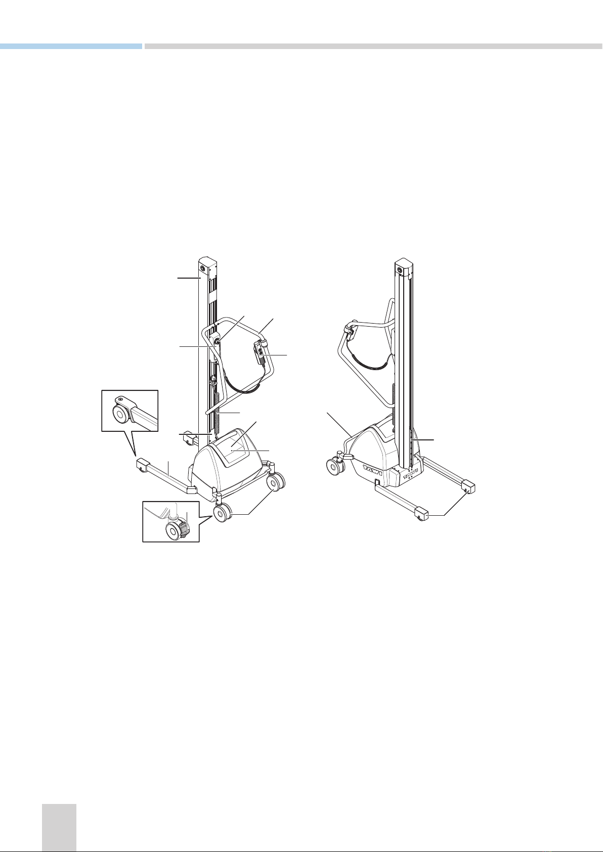
A Mast
B Control panel
C Emergency stop
D Identification plate
E Leg
F Rear wheels separately braked (PRO40)
G Rear wheels
H Battery charging indicator
J Battery pack
K Power cord
L Hand control (all models except PRO40)
M Handle
N Central brake
P Sleigh
Q Front wheels
R Swiveling front wheels (PRO40 and PRO80)
1 Overview
TAWI Lifting Trolleys provide lifting and transportation aid for loads up to 250kg (551lbs). The lifters can be
equipped with different tools that have battery driven lifting and lowering capabilities. The user moves the lifter
by pushing it, and prevents it from moving when stationary with the aid of brakes.
The lifters are available in seven different models, mainly differing in lifting capacity: PRO40, PRO80, PRO140,
PRO180, PRO250, PRO100ESE and PRO200ESE. This chapter presents an overview illustration of the lifters
and a table containing characteristics of the different models. Important information about how to load the lift-
ers is also provided.
A
D
B
E
J
H
G
K
L
CM
N
Q
P
F
R

03
Model PRO40 PRO80 PRO140 PRO180 PRO250 PRO100ESE PRO200ESE
Lifting
capacity
40kg/
88lbs
80kg/
176lbs
140kg/
308lbs
180kg/
379lbs
250kg/
551lbs
100kg/
220lbs
200kg/
441lbs
The lifting capacity is valid only in accordance to the appropriate load diagram, see Loading on page 04.
The max lifting capacity specified above are valid for standard configurations of the lifters. Check the sticker on the mast for
applicable max load.
Max lifting
height
1640mm/
64.5in
2540mm/
100in
2540mm/
100in
2540mm/
100in
2540mm/
100in
2222mm/
87.4in
2195mm/
86.4in
The max lifting height specified above concern lifting heights with preserved max lifting capacity. These are valid for stan-
dard configurations of the lifters.
Weight short/
medium/long
mast
- /
41kg (90lbs)
/-
46kg
(101lbs)/
50kg
(110lbs)/
53kg
(116lbs)
69kg
(152lbs)/
73kg
(160lbs)/
78kg
(171lbs)
77kg
(169lbs)/
81kg
(178lbs)/
86kg
(189lbs)
- /
107kg
(238lbs)/
113kg
(249lbs)
Electrical
EasyTurn:
- /
115kg (253lbs)/
120kg (265lbs)
- /
152kg
(335lbs)/
158kg
(348lbs)
Manual
EasyTurn:
- /
113kg (249lbs)/
118kg (260lbs)
The weight is valid for standard configurations of the lifters without tools.
Battery
charging
procedure
Plug in to electrical outlet (100-240 V, grounded, 50 - 60 Hz)
Recommended 8 hours continuous charge
Lifts per
charge
40kg
(88lbs),
1m (39.3in)
x 100 times
80kg
(76lbs),
1m (39.3in),
x 100 times
140kg
(308lbs),
1m (39.3in),
x 100 times
180kg
(397lbs),
1m (39.3in),
x 100 times
250kg
(551lbs),
1m (39.3in),
x 100 times
100kg
(220lbs),
1m (39.3in),
x 100 times
200kg
(441lbs),
1m (39.3in),
x 100 times
Up and down
motions
Control
panel. One
speed.
Hand control. Two speeds.
Front wheels Swiveling Swiveling Fixed
Brake system Rear wheels
separately
braked
Central brake with directional lock.
Overload
protection
Incorporated in circuit load
This table presents information about STANDARD CONFIGURATIONS of each model.

04
Load diagram PRO140Load diagram PRO80
Valid for y-distances between 0 - 2540mm (0 - 100in).
Load diagram PRO40
Loading
The max lifting capacity of the lifters depends on where the mass centre of the load is located in terms of x and
y distances. The graphs in the load diagrams display allowed x-distances and the text above each load diagram
presents allowed y-distances.
Valid for y-distances between 0 - 1640mm (0 - 64.5in).
Illustration of x and y-distances
PRO40, PRO80, PRO140, PRO180 and PRO250
Valid for y-distances between 0 - 2540mm (0 - 100in).
Kg
X
Y

05
Load diagram PRO180 Load diagram PRO250
Load diagram PRO100ESE
Load diagram PRO200ESE
Illustration of x and y-distances
Valid for y-distances between 0 - 2195mm (0 - 86.4in).
Valid for y-distances between 0 - 2540mm (0 - 100in). Valid for y-distances between 0 - 2540mm (0 - 100in).
Valid for y-distances between 0 - 2222mm (0 - 87.4in).
PRO100ESE and PRO200ESE
X
Y(x) mm

6
Fasten tools on the sleigh
Sometimes tools are attached at delivery. If not, at-
tach the tool to the sleigh with at least three screws.
Select which holes to use in order to get the desired
max and min lifting heights.
1. Align the selected holes for attachment on the
tool with the ones on the sleigh.
2. Fasten with at least three screws.
2 Quick start
This chapter presents how to fasten tools and how to start the lifter.
Torques to apply
Tool attachment for
model
Type Torque (Nm,
class 8.8) (ft/lb)
PRO 40 and PRO80 M6 10 Nm
(7.3 ft/lb)
PRO140 and PRO180 M8 24 Nm
(17.7 ft/lb)
PRO250 M10 47 Nm
(34.6 ft/lb)
• Make sure the screws are fastened correctly
and that the correct torque is applied on
each screw.
• Make sure the screws are dimensioned to
carry the weight of the tool plus the max load.
• When fastening EasySqueeze arms, use four
screws (type M8) per arm.
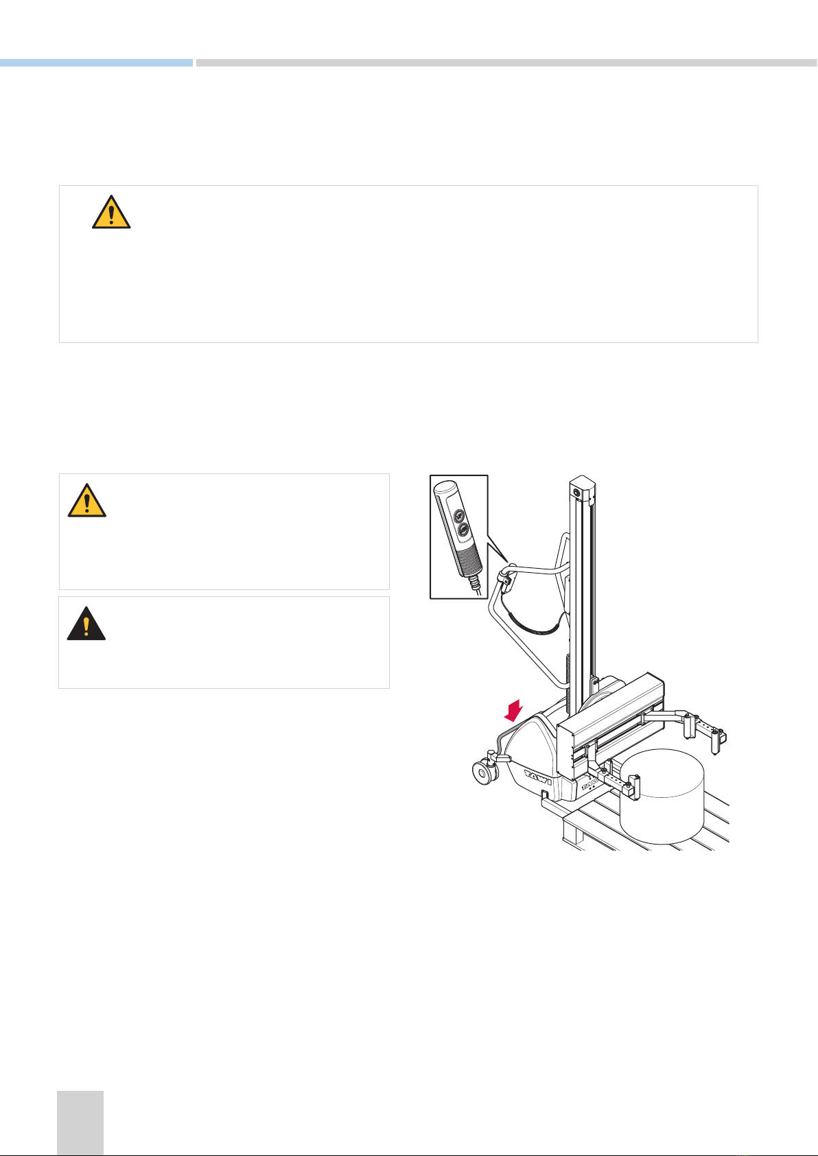
Lift the lifter
To transport the lifter by lifting it, fasten a sling in the
handle according to illustration and lift.

7
3 User instructions
This chapter describes how to operate the TAWI Lifting Trolleys.
• A damaged power cord could cause electrical shock.
• Never touch any parts inside the battery pack when charging. Touching electrical parts can cause an
electric shock.
Charge the battery
The battery can be charged with the battery pack attached or detached from the lifter. The battery can not be
overcharged or charged too often. It is recommended to charge the battery as soon as it is not in use.
Start the lifter
Make sure that the wheels rotate smoothly, that the brakes on the rear wheels are functioning properly and that
the battery is charged. Review and perform relevant inspections. See Daily inspections by operator on page
20, Quarterly inspections by inhouse maintenance on page 21 and Yearly inspections by TAWI authorised
service technician on page 21.
1. Press the main switch to turn the power on.
»Response: The battery status display flashes for approximately three seconds and is thereafter lit.
2. The lifter is now ready for use.
• The lifter can be stopped at any time by pressing the emergency stop on the control panel.
• Only run the lifter when it is completely assembled.
• Check the lifter for safe functionality prior to each use, for instructions, see Inspections on page 20.
• The lifters has overload protection which will prevent tools from being raised when the specified max
load is exceeded. If the overload protection is activated, reduce the load and try again.

8
100-
240V
100-
240V
Charge with battery pack attached
1. Connect the power cord to a grounded electri-
cal outlet (100 - 240 V, 50 - 60 Hz).
2. When the battery is charged, pull the power
cord out of the electric outlet and fasten it in its
holder on the mast.
Charge with battery pack detached
1. Grab the battery pack handle and lift vertically
to detach it from the lifter.
2. Place the battery in a designated dry area for
charging.
3. Connect the power cord to a grounded electri-
cal outlet (100 - 240 V, 50 - 60 Hz).
4. When the battery is charged, pull the power
cord out of the electric outlet.
5. Place the battery back into position.
6. Fasten the power cord in its holder on the mast.
• The lifter can be switched on or off when charging the battery. It is recommended that the lifter is
switched off.
• To make sure not to damage the cord when pulling it out of the electrical outlet - grab, and apply the
force to the plug.
• It is recommended to charge the battery in a full cycle, however the battery system can be plugged in
for a longer period, since it cannot be overcharged. See Battery charging indicator on page 9.
• Never operate the lifter when the battery is charging (plugged in).
• The battery system has to be charged in a grounded electrical outlet.
• Charge the battery in a designated dry area.
• Normal charging of the battery creates very small amounts of hydrogen. However, the casing is venti-
lated, and thereby the risk of hydrogen collection is minimal.

9
Battery charging indicator
The colour of the battery charging indicator communicates the following information:
PRO40 and PRO80
Orange Boost charge
Yellow Top up charge
Green Ready/standby
PRO140, PRO180, PRO250, PRO100ESE and
PRO200ESE
Yellow (steady) Boost charge
Yellow (flashing) Top up charge
Green Ready/standby
Red Error
Move the lifter
Grab the handles and push the lifter to move it forward.
Always move the lifter with the load in a lowered position.
10
A
C
B
A
B
A
B
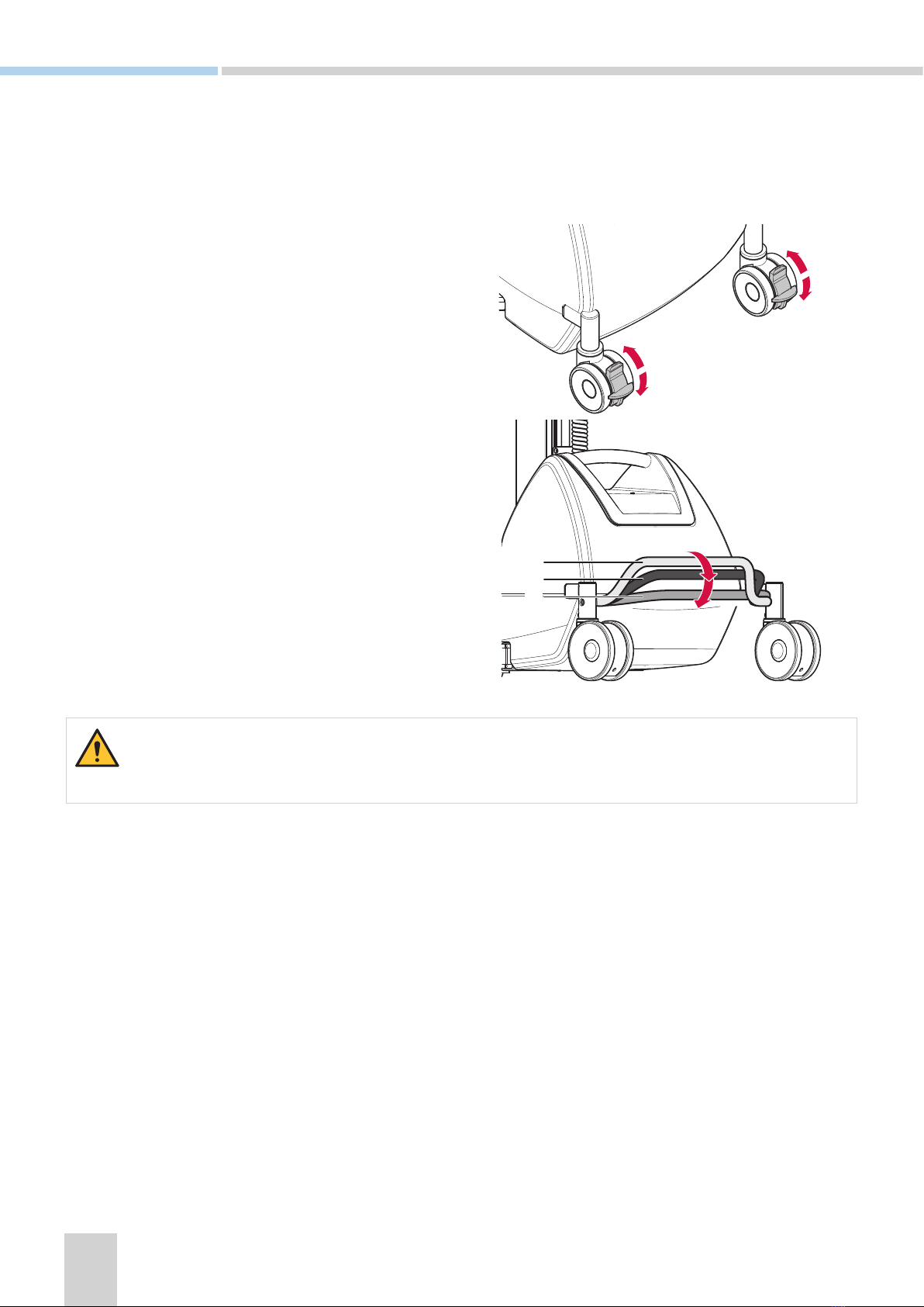
Rear wheels separately braked (PRO40)
Engage or disengage the brakes on both rear
wheels.
A. Neutral
B. Brake
Central brake (all models except PRO40)
The central brake has three positions; brake, re-
lease, and directional lock. Directional lock means
that the rear wheels are locked in a fixed position,
only allowing the lifter to move straight forward
and straight backwards. This feature keeps the lifter
steady and is helpful when it is transported a rela-
tively long distance.
A. Directional lock
B. Neutral
C. Brake
Always apply brakes when loading and unloading.
Apply brakes to the lifter
There are two different brake options depending on the model of the lifter; rear wheels separately braked or
central brake.
11
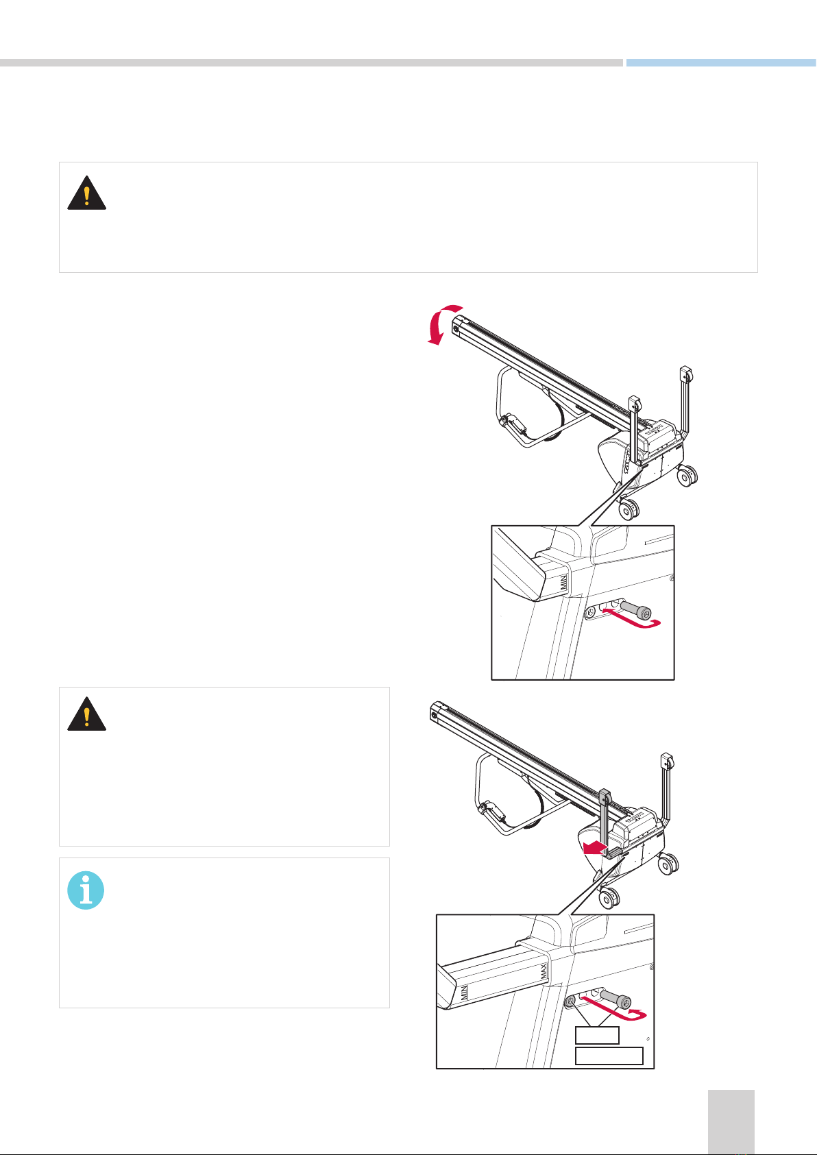
Always apply brakes and take out the battery pack before leaning the lifter. Also make sure that no cables are
in the way or squeezed between the operator handle and the floor.
1. Lean the lifter and place it on its back.
2. Adjust the legs one side at a time:
a. Loosen and remove the screw closest to the
mast.
b. Loosen, but do not remove, the other screw
(located farthest away from the mast).
c. Refit the removed screw into the middle posi-
tion to enable the leg to move inwards and
outwards.
d. Extend the leg to desired position, make sure
it ends up within the max and min markings.
e. Remove the screw from the middle position.
f. Put the screw back and fasten into its original
position.
g. Make sure both screws are tightened to
24Nm (17.7 ft/lb).
3. Repeat step (2) for the other leg.
• Always adjust the legs within the max and min
markings.
• Exceeding this may cause damage to the lifter
and may cause injuries.
• The legs do not have to be adjusted
symmetrically.
• Each leg is adjustable by 150mm (5.9in).
Adjust legs
This section only applies to PRO80 and PRO140. The legs of these models can be adjusted in width.
24Nm
17.7 ft/lb
12
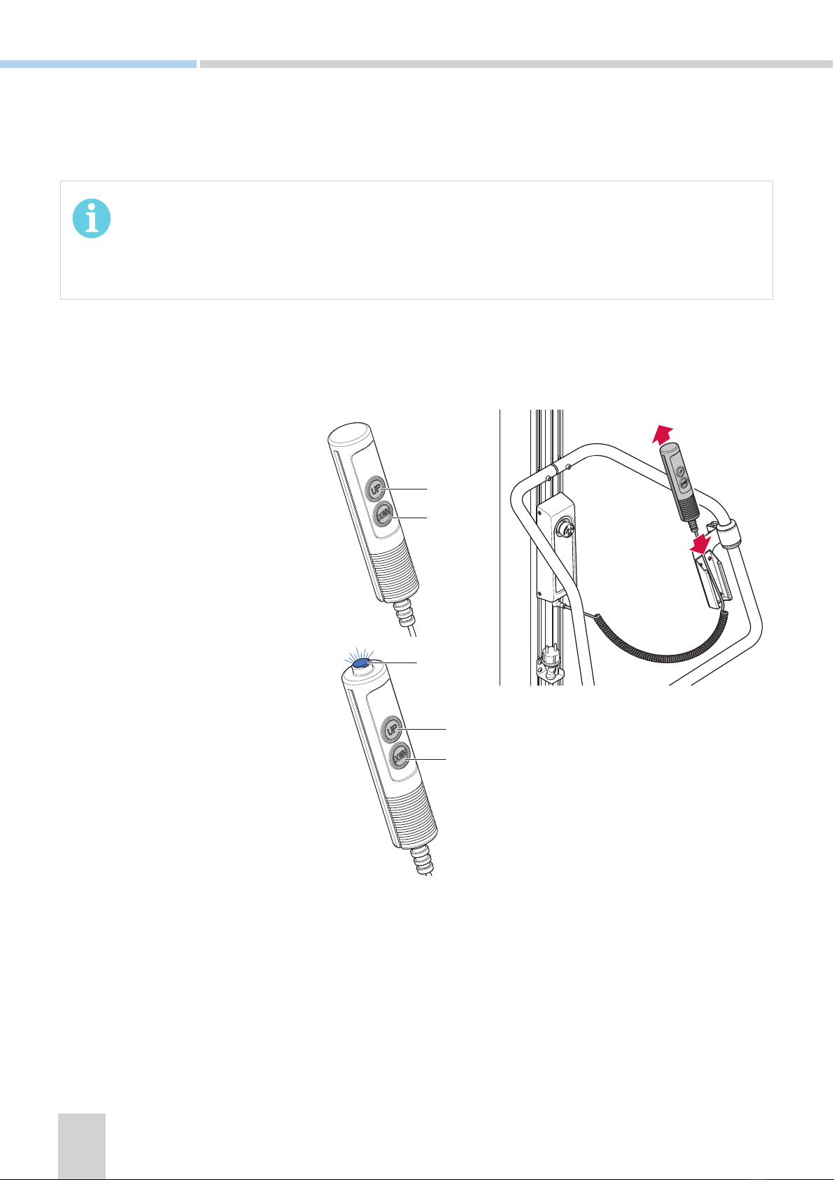
B
A
Standard hand control
A. Press UP to raise
B. Press DOWN to lower
The Position stop hand control has
a button on top, see Position stop
on page 19.
A. Press UP to raise
B. Press DOWN to lower
C. Press the top button on top to
activate Position stop.
B
A
C
Operating tools
Tools are handled using a detachable hand control and the control panel. If the lifter is not equipped with a
hand control, only the control panel is used.
Raise and lower with the hand control
The hand control can be detached from the handle and has two buttons, up and down. The hand control is
equipped with two speeds. Press firmly for faster movement and press lightly for slower movement.
If a tool hits an object or surface during lowering, a safety mechanism will stop the downwards movement.
This is to prevent accidents.

13
A. Emergency stop
B. Close squeeze arms
C. Open squeeze arms
D. Rotate counterclockwise
E. Rotate clockwise
F. Battery status display
H
G
K
A
F
J
E
C
A
F
D
L
B
H
G
F
A
H
G
Control panel
There are three standard configurations of the control panel, they depend on the model of the lifter.
G. Service indicator
H. Main switch
J. Raise the tool (one speed)
K. Lower the tool (one speed)
L. Safety button
Battery status display
The battery status is indicated by the number of lit bars in the battery status display. When the bars are flashing,
the number of flashing bars communicate messages, see Codes on the battery status display on page 25.
Control panel on lifter equipped
with EasySqueeze.
Control panel on lifter
equipped with a hand control.
Control panel on lifter NOT
equipped with a hand control.
14
EasySqueeze
The EasySqueeze is an electrical gripping tool that handles objects from their outer surfaces. The EasySqueeze
is operated from the control panel, see Control panel on page 13 for illustrations of the buttons to use.
General tools
General tools includes platforms, fork tools etcetera, see Tools on page 36 for additional examples. These
can be used to raise and lower loads and objects using the hand control and/or the control panel.
• Make sure that the load is stable and is secured on the general tool.
• Make sure the general tool is loaded according to load diagrams, see Loading on page 04.
• Always transport a load in a lowered position.
• Always stay clear of the area under the tool.
• Do not stand between the grippers.
Apply brakes when loading and unloading.
15
Grip an object
1. Move the lifter and use the hand control to
place the EasySqueeze arms centred in height
and depth over the object that is to be moved.
2. Press the Close squeeze arms (B) button and
keep it pressed.
»Response: When the preset gripping force is
reached, the EasySqueeze arms stop and the
Close squeeze arms (B) button is lit green.
Make sure all grippers are pressed against the
surface of the object. If they are not, loosen the
EasySqueeze arms and repeat step 2.
Rotate an object
When an object is gripped with the EasySqueeze
and raised approximately 20cm (7.8in), it is possible
to rotate the object clockwise or counterclockwise.
1. Press and hold the Rotate counterclockwise (D)
button or the Rotate clockwise (E) button.
2. Release the button when the desired or pre-
defined angle is reached.
»Response: When the button is released, the
rotation stops.
Transport an object
Transport the object at a lowered position (in this
case, appoximately 20cm (7.8in) above ground
level).
It is desireable to transport the object in an angle
where it is resting on one of the EasySqueeze
arms.
1. Raise the object approximately 20cm (7.8in)
above ground level.
2. Release the brake.
3. Grab the handle and push the lifter to desired
location.
B
E
D
16
Release an object
• Make sure there is enough space when
unloading so that the EasySqueeze arms do
not collide with any surrounding items when
moving outwards to release the object.
• Do not release an object during raising or
lowering.
1. Apply the brake.
2. If applicable, rotate the object to the desired
angle for unloading.
3. Use the hand control to raise the object to de-
sired height for unloading.
Make sure that the object is placed in the correct
position and that it is safe to release it.
4. Press the Open squeeze arms (C) button and the
Safety button (L) simultaneously and keep the
buttons pressed to release the object.
C
L
17
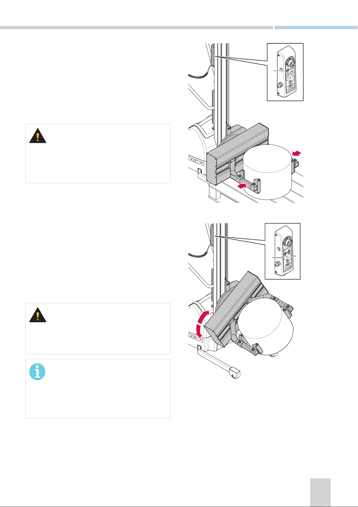
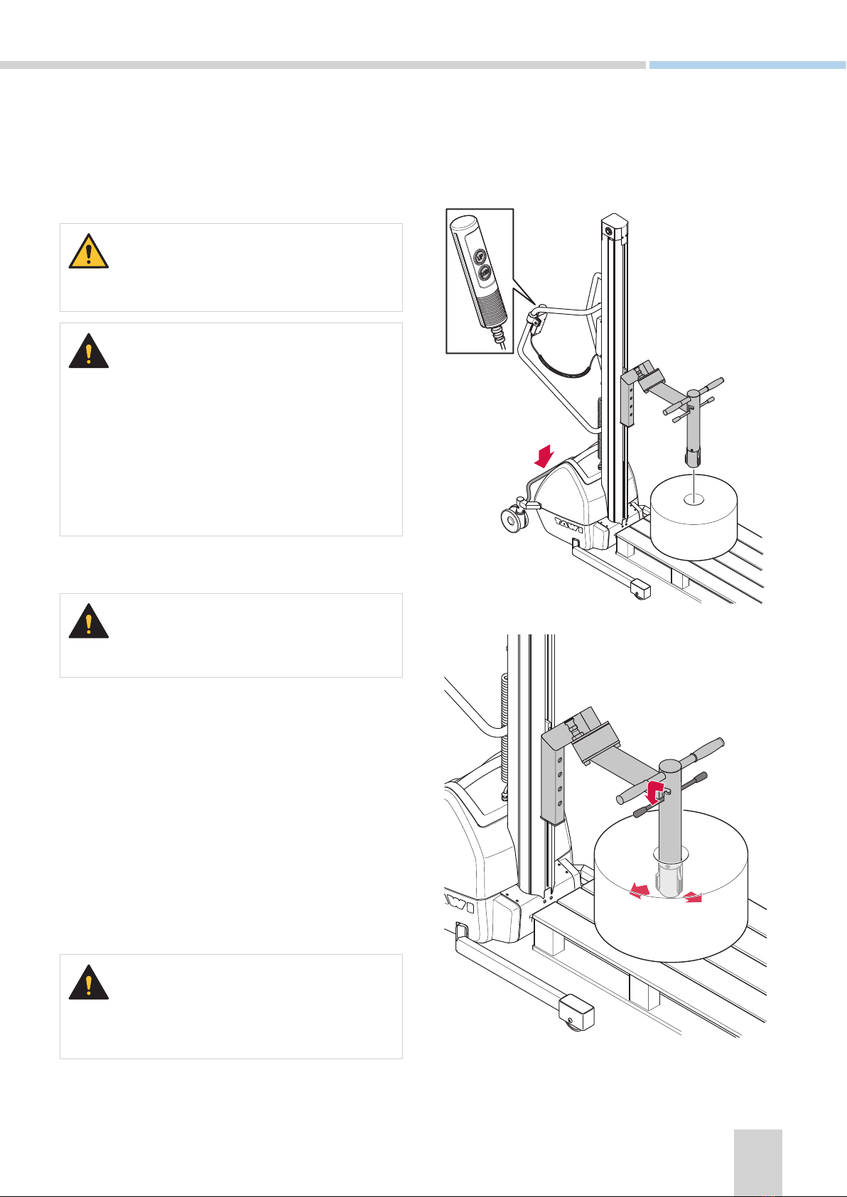
Pick up and rotate a reel
Always stay clear of the area under the reel.
• The Coregripper is mainly designed to pick
up reels with the core in a vertical position.
• When lifting reels with the core in horisontal
position, the reel can fall off the Coregripper.
Make sure there is a secure grip before
rotating.
1. Move the lifter and place the centre of the
Coregripper above the core of the reel.
Apply brake to the rear wheels.
2. Press and hold the Down button on the hand
control to lower the Coregripper into the core of
the reel.
3. Release the Down button when the Coregripper
has reached desired depth.
4. Activate the gripping jaws by lifting the extractor
handle out of its slots. Use both hands.
5. Press and hold the Up button on the hand con-
trol to lift the reel.
6. Raise the reel approximately 20cm (7.8in) from
ground level to check that the core is gripped
safely.
Make sure nobody is close to the lifter when pre-
paring to rotate the reel.
Coregripper
The Coregripper is a reel handling tool that handles the reel from the core. It is designed to handle reels with
a cardboard core. See Control panel on page 13 for illustrations of the buttons to use when operating an
electrical Coregripper.

18
7. Rotate the Coregripper to horisontal position by
grabbing the OPPOSITE side of the handle from
the side you stand with reference to the mast.
8. Pull the rotation lock pin outwards and hold.
9. Pull the handle to rotate the reel.
10. Carry the rotation through before putting the
rotation lock pin back gently.
For an effortless rotation, try to place the reel so
that its center of gravity ends up on the axis of
rotation.
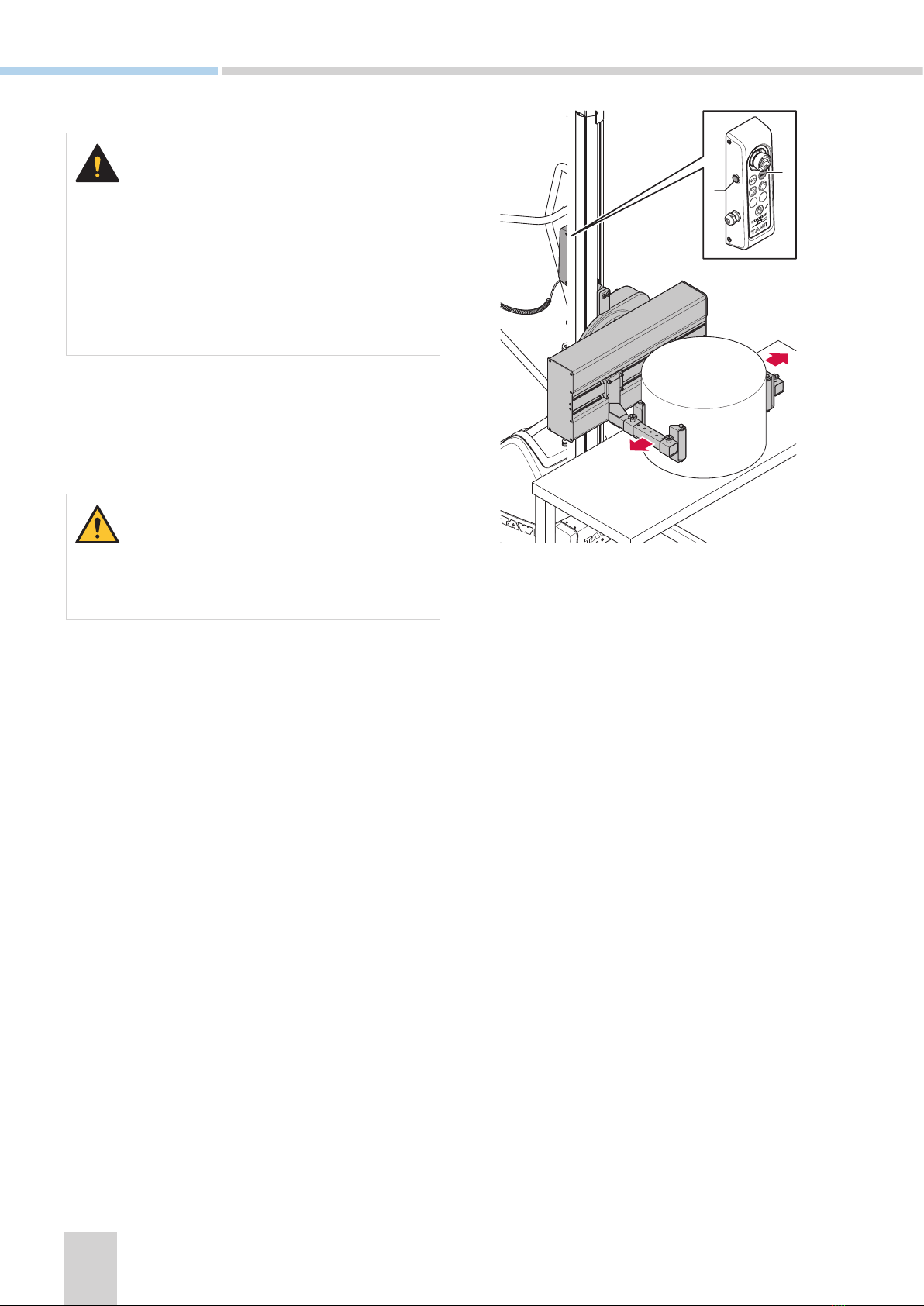
Transport a reel
1. Release the brake and push the lifter to desired
location
• Always transport the reel with the core in hor-
isontal position.
• Always transport objects at a lowered
position.
Release a reel onto a shaft
1. Push the lifter and raise the Coregripper to de-
sired height (until it is in line with the shaft).
Make sure brakes are applied to the rear wheels
when handling the reel.
2. Disengage the gripping jaws by putting the
extractor handle back in its slots.
3. Manually push the reel onto the shaft.

19
Position stop
A Position stop switch can be assembled on the mast between the top and bottom position switches. The
Position stop can also be assembled at delivery
Ladder
TAWI Lifting Trolleys have a ladder accessory which can be used to facilitate work. Be careful when using the lad-
der accessory along with the lifter, and pay attention to the sticker on the ladder, see Label on TAWI Lifting Trolley
ladder on page 10.
When using a ladder there is a risk of slipping and falling off it. Be careful and make sure:
• To have a good grasp of a supporting object when stepping onto and climbing the ladder.
• To have clean shoes with a good grip.
• That the ladder is clean and provides a good grip for your feet.
• Do not exceed the max load of the ladder, see Label on TAWI Lifting Trolley ladder on page 10.
• The brake must be applied on the lifter when using the ladder.
1. The Position stop hand control has a button on top.
2. Press the top button (C) to activate the Position stop.
»Response: The top button (C) is activated and lit.
3. Depending on how the Position stop is configured, press UP (A) or
DOWN (B) to move the tool to desired position.
4. The tool stops when reaching the Position stop.
»Response: The tool stops.
5. Press the top button (C) to move the tool past the position switch.
»Response: The top button (C) stops being lit.
B
A
C
The Position stop is configured to stop the tool when the tool moves upwards or downwards. Contact a TAWI
authorised service technician for support with configuration of the Position stop.
• There is always one top limit switch and one bottom limit switch assembled on the lifter. Make sure the
Position stop switch is placed between the top and bottom limit switches.
• NEVER move the top or bottom limit switches.

20
4 Service & maintenance
This chapter provides information about service and maintenance of the lifters. The chapter is divided into three
sections based on who is to perform the inspections and how often the inspections are to be carried out. Daily
by the operator, quarterly by inhouse maintenance or yearly by TAWI authorised service technician.
For technical service, maintenance or repairs contact your TAWI representative or [email protected]. TAWI must
authorise all modifications to this product. TAWI assumes no responsibility for unauthorised modifications and
guarantees will automatically become invalid if unauthorised modifications have been made.
Inspections
The following inspections are to be carried out.
• Service must be carried out on a yearly basis or when the service indicator lamp (see G. Service indicator
on page 13) on the control panel is lit.
• If any damage/wear is detected on the lifter, this must immediately be reported to TAWI or authorised
TAWI representative. The lifter must be taken out of commission and not be used until the damage has
been repaired.
• All service must be carried out with the battery disconnected. The battery pack can be lifted out in order
to remove the power source.
• In order to deal with the lifter’s cables and wiring, a good knowledge of electricity and TAWI electrical
schedules of the lifters is required.
Daily inspections by operator
1. If yearly service has been carried out, make sure that the service inspection date is valid.
2. Check that the max lifting capacity signs are visible.
3. Check that warning and operating labels are visible.
4. Make sure wheels and bearings are functioning and running smoothly.
5. Make sure breaks are functioning correctly and check for signs of damage/wear.
6. Check external wiring for damage/wear.
7. Make sure that the hand control is functioning properly.
• If the battery needs to be replaced, either order a new battery pack from TAWI or make sure that an
original battery is used. If assistance is needed, contact TAWI.
• Keep the lifter clean, use a damp cloth. Do not use chemical cleaners.
Continue on the next page
This manual suits for next models
6
Table of contents


