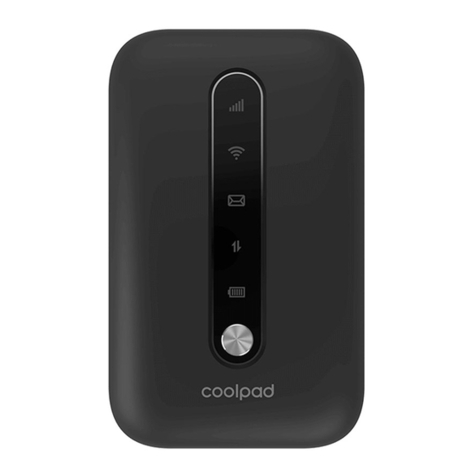
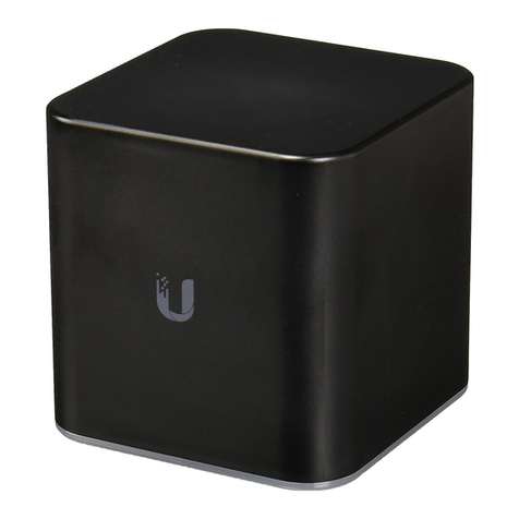
Taylor Made AquaFi 781414 Installation instructions

1
taylormadeproducts.com/aquafi 574-534-7521 aquafisupport@lci1.com Rev:08.01.19
AquaFi™
Installation and Owner’s Manual
(For Aftermarket Applications)
CCD-0002558
Table of Contents
Introduction �������������������������������������������� 1
Safety ��������������������������������������������������� 1
Parts List ������������������������������������������������ 2
Resources Required ����������������������������������� 2
Installation ���������������������������������������������� 2
Activation ����������������������������������������������� 4
System Requirements ��������������������������������� 4
Preparation �������������������������������������������� 4
AquaFi System Activation ����������������������������� 5
Connecting to the Hotspot ����������������������������� 5
Changing Network Name and Password ������������� 6
Mobile Use ���������������������������������������������� 8
Troubleshooting ���������������������������������������� 9
Maintenance �������������������������������������������� 9
FCC Compliance �������������������������������������� 10
FCC 15B statement ���������������������������������� 10
FCC Part 15 compliance statement ������������������ 10
IC User manual notice ������������������������������� 10
RF Exposure Statement ����������������������������� 10
Wiring Diagrams ������������������������������������� 11
Watercraft ������������������������������������������� 11
Notes �������������������������������������������������� 12
AquaFi TM
Installation and
Owner’s Manual
(For Aftermarket Applications)
AquaFiTM Kit
Part # Description
781414 AquaFiTM Hotspot
Introduction
The Taylor Made®AquaFi™Hotspot provides boating
enthusiasts with wireless Internet connectivity� A secure
2�4 GHz WiFi network connects devices to the Internet
at 4G LTE speeds up to 150 Mbps� All antennae are fully
contained for a splash-proof solution� The 12V DC power is
sourced through a mounting dock with snap-in portability�
The AquaFi™Hotspot can be removed from its mounting
dock and operated on-shore utilizing an included AC-to-
DC wall plug power supply� The SIM card slot and power
port are accessible by removing the side compartment
cover� Compatible with 4G LTE Bands 2, 4 and 12�
Additional information about this product can be obtained
from taylormadeproducts�com/aquafi�
NOTE: AquaFi Hotspot screen images are from an iOS
mobile device� Screen images from an Android mobile
device may appear slightly different�
Safety
Read and fully understand all instructions before installing
or operating this product� Adhere to all safety labels�
This manual provides general instructions� Many variables
can change the circumstances of the instructions, i�e�, the
degree of difficulty, operation and ability of the individual
performing the instructions� This manual cannot begin to
plot out instructions for every possibility, but provides

2
taylormadeproducts.com/aquafi 574-534-7521 aquafisupport@lci1.com Rev:08.01.19
AquaFi™
Installation and Owner’s Manual
(For Aftermarket Applications)
CCD-0002558
AquaFi Kit—781414
Letter PN Description Qty
A 781411 AquaFi Hotspot Assembly 1
B 781413 AquaFi Hotspot Dock Assembly 1
C 722253 120V AC/DC Power Supply 1
the general instructions, as necessary, for effectively
interfacing with the device, product or system� Failure to
correctly follow the provided instructions may result in death,
serious personal injury, severe product and/or property
damage, including voiding of the LCI limited warranty�
• Phillips screwdriver
• Heat gun
• Heat shrink tubing
• Four #8 pan head screws
• Two butt connectors
• Wire crimpers
• Wire strippers
• 18 AWG power and ground
wire (depending on location
of installation related to
power source)
THE “CAUTION” SYMBOL ABOVE IS A SIGN
THAT AN INSTALLATION PROCEDURE HAS
A SAFETY RISK INVOLVED AND MAY CAUSE
PERSONAL INJURY OR PRODUCT DAMAGE IF
NOT PERFORMED SAFELY AND WITHIN THE
PARAMETERS SET FORTH IN THIS MANUAL.
THE “WARNING” SYMBOL ABOVE IS A SIGN THAT
AN INSTALLATION PROCEDURE HAS A SAFETY
RISK INVOLVED AND MAY CAUSE DEATH OR
SERIOUS PERSONAL INJURY, SEVERE PRODUCT
OR PROPERTY DAMAGE IF NOT PERFORMED
SAFELY AND WITHIN THE PARAMETERS SET
FORTH IN THIS MANUAL.
Fig.1
Parts List
NOTE: Part numbers are shown for identification purposes
only� Not all parts are available for individual sale� All parts
with a link to the Taylor Made Store can be purchased�
Resources Required
Installation
1. Make sure watercraft is dry-docked or otherwise
supported above water to avoid an unstable condition
created by waves�
2. Locate a mounting area that allows connection of the
AquaFi Hotspot Dock Assembly’s power and ground wires
to the watercraft’s power source without creating a strain
on the completed connection�
NOTE: Vertical orientation of product at installation is required�
NOTE: The mounting dock should be easily accessible
with enough room to remove the AquaFi Hotspot Assembly
from its dock�
3. If necessary, remove the AquaFi Hotspot (Fig.2A) from its
mounting dock (Fig.2B) and set aside for later use�
A. Slightly lift and hold the top clamping tab�
B. Pivot the hotspot unit forward and release the
clamping tab�
4. Connect the mounting dock’s red power (Fig.3A) and
black ground (Fig.3B) electrical wires to the appropriate
wires of the watercraft’s power system with crimp-style butt
connectors (Fig.3C)�
A
B
C

3
taylormadeproducts.com/aquafi 574-534-7521 aquafisupport@lci1.com Rev:08.01.19
AquaFi™
Installation and Owner’s Manual
(For Aftermarket Applications)
CCD-0002558
Fig.2
A. If necessary, use wire strippers to expose enough
bare wire to make a good electrical connection within the
butt connector�
B. Cut a 1 ½” long strip of heat shrink tubing� Slip tubing
onto electrical wire�
Fig.3
A
B
C. Insert the docking wire into one open end of the butt
connector, then crimp butt connector in-place using a
crimping tool�
D. Insert 12V DC electrical system wire into the
remaining open end of the butt connector� Crimp butt
connector in-place�
E. Slide heat shrink tubing over the connection� Apply
heat gun to the tubing� to seal the connection�
F. If using heat shrink/crimp butt connectors, additional
heat shrink tubing is not required� Do as follows:
I. Insert wire into butt connector�
II. Crimp butt connector�
III. Repeat steps I and II on the other connector end�
IV. Use a heat gun on the butt connector to seal it
against the electrical wires�
NOTE: Make sure the electrical connections are secure
and protected against water�
5. Secure the AquaFi Hotspot Dock Assembly to the
watercraft with four #8 pan head screws (Fig.4A)�
Fig.4
A
to watercraft
12V DC power
C
A
B
NOTE: Mounting dock electrical wires (Fig.3A and B) are
6” long�

4
taylormadeproducts.com/aquafi 574-534-7521 aquafisupport@lci1.com Rev:08.01.19
AquaFi™
Installation and Owner’s Manual
(For Aftermarket Applications)
CCD-0002558
App Store®is a trademark of Apple Inc.
AndroidTM and Google PlayTM are trademarks of Google LLC.
App Store
Fig.5
Activation
A data package is required to activate the AquaFi wireless
Internet system� Go to taylormadeproducts�com/aquafi for
data plan activation� Have the IMEI (International Mobile
Equipment Identity) number, Make and Model of the
watercraft and a credit card available�
The IMEI number is on the product label located on the
backside of the AquaFi Hotspot Assembly�
System Requirements
• Data package
• Android or iOS smart device
• AquaFi app
Preparation
AquaFi system activation requires the AquaFi app installed
on a smart phone, or other smart device�
1. Download the AquaFi app (Fig.5) from either Apple’s App
Store (iOS) or Google Play (Android)�
2. Install the AquaFi app onto the smart device�
3. Go to Wi-Fi settings on the mobile device (Fig.6), then
select the hotspot’s AquaFi SSID (Fig.6A) from the list of
available wireless networks�
4. Make sure the selected network name (Fig.6A) matches
the SSID name located on the backside of the AquaFi
Hotspot Assembly (Fig. 7A)�
A
Fig.6
Fig.7
A
B

5
taylormadeproducts.com/aquafi 574-534-7521 aquafisupport@lci1.com Rev:08.01.19
AquaFi™
Installation and Owner’s Manual
(For Aftermarket Applications)
CCD-0002558
5. Launch the AquaFi app�
6. Enter the Username and Password (Fig.8A) printed on
the product label (Fig.7B)�
7. After entering the login credentials, tap the Login
button (Fg.8B)�
AquaFi System Activation
Activation of the AquaFi Hotspot system can be performed
on shore or on a watercraft�
If activating the system on shore, the 120V AC/DC
power supply (Fig.1C) is required� Refer to the On Shore
Use section�
1. Make sure watercraft is dry-docked or otherwise
supported above water to avoid an unstable condition
created by waves�
2. Make sure the AquaFi Hotspot is securely seated in its
mounting dock� The dock should snap onto the hotspot�
NOTE: A secured AquaFi Hotspot will make good
electrical connections across the mounting dock and
hotspot mating contact pins�
3. Turn system power on�
4. All LEDs should light up (Fig.9A)�
NOTE: The LEDs will flash blue as the AquaFi system
boots up, then green in a steady state when the system
connects to 3G/4G LTE�
Fig.8
B
A
A
NOTE: If LEDs are red, this indicates one of the
following conditions exists: no service, no SIM card or a
2G less connection�
Connecting to the Hotspot
1. After a successful connection has been established, go
to Wi-Fi settings on the mobile device (Fig.10A), then select
the hotspot’s AquaFi SSID (Fig.11A) from the list of available
wireless networks�
Fig.9
Fig.10
A
2. When prompted, enter the username and password
(Fig.12A) located on the product label (Fig.7B)�
3. After login credentials have been entered (Fig.13A), press
the Login button (Fig.13B)�
4. The AquaFi Home screen will display showing
SETTINGS (Fig.14A) and BANDWIDTH (Fig.14B) options�

6
taylormadeproducts.com/aquafi 574-534-7521 aquafisupport@lci1.com Rev:08.01.19
AquaFi™
Installation and Owner’s Manual
(For Aftermarket Applications)
CCD-0002558
A
Fig.12
Fig.13
Fig.14
Changing Network Name and
Password
1. From an established network connection, the Settings
screen (Fig.15) shows three options:
A. SSID—Change WiFi SSID and Password (Fig.15A)
B. Login—Change administrator password (Fig.15B)
A
Fig.11
B
A
A B

7
taylormadeproducts.com/aquafi 574-534-7521 aquafisupport@lci1.com Rev:08.01.19
AquaFi™
Installation and Owner’s Manual
(For Aftermarket Applications)
CCD-0002558
C. Advanced—View and update advanced settings (Fig.15C)
Fig.15
A
B
C
NOTE: The SSID is the network name and Password
is used to connect to the hotspot� The Login changes
the administrator password used to access the mobile
app—AquaFi� The Advanced settings allows viewing and
updating of select advanced settings�
2. To change the WiFi SSID name, tap the right bracket (>)
to display the Change WiFi Info screen (Fig.16)�
3. Highlight the current SSID name (Fig.16A), then type in
the new name�
4. Next, select the Password eld (Fig.16B) and enter a new
password for the new WiFi SSID�
5. Press the Enter button (Fig.16C) to apply the changes or
Cancel (Fig.16D) to retain default settings�
6. If the Enter button was pressed, the Success screen
(Fig.17) will display�
7. Press the OK button (Fig.17A) to reboot the hotspot and
login to the recongured system with the new credentials.
8. Go to the device’s WiFi settings and select the new
SSID network name (Fig.18A)�
9. Enter the password for the new SSID network (Fig.19A)�
10. To change the Login administrator password, go to the
AquaFi Home Settings screen (Fig.15) and select the Login
option (Fig.15B)�
Fig.16
A
B
C
D
A
Fig.17

8
taylormadeproducts.com/aquafi 574-534-7521 aquafisupport@lci1.com Rev:08.01.19
AquaFi™
Installation and Owner’s Manual
(For Aftermarket Applications)
CCD-0002558
11. Tap the right bracket (>) to display the Change Admin
Password screen (Fig.20)�
12. Select the New Password eld (Fig.20A) and enter
a new administrator password, then select the New
Password Again eld (Fig.20B) and re-enter the new
administrator password�
13. Press the Enter button (Fig.20C) to apply the changes
or Cancel (Fig.20D) to retain default settings�
14. To reconnect, go to Wi-Fi settings on the mobile device,
then when prompted, enter the new login credentials�
Fig.18
A
A
Fig.19
Fig.20
A
B
C
D
On Shore Use
To use the AquaFi Hotspot on shore, do as follows:
1. Remove the hotspot unit from its mounting dock (Fig.2)�
A. Slightly lift and hold the top clamping tab�
B. Pivot the hotspot unit forward and release the
clamping tab�
2. Take the hotspot and the 120V AC/DC power supply
(Fig.1C) to a shore-based 120V wall outlet�

9
taylormadeproducts.com/aquafi 574-534-7521 aquafisupport@lci1.com Rev:08.01.19
AquaFi™
Installation and Owner’s Manual
(For Aftermarket Applications)
CCD-0002558
5. Insert the power supply’s barrel connector into the
hotspot’s power supply port (Fig.22A)�
6. Plug the 120V AC/DC power supply (Fig.22B) into a wall
outlet (Fig.22C)�
7. Go to the mobile device’s WiFi settings�
A. Select the AquaFi network�
B. Enter login credentials to reconnect to the
AquaFi network�
3. Remove the access door (Fig.21A) by unscrewing the two
Phillips pan head screws (Fig.21B)�
4. Set the screws and access door aside for later installation�
REMOVAL OF ACCESS DOOR EXPOSES INTERNAL
COMPONENTS TO CONTAMINATION BY WATER.
WATER CONTAMINATION CAN SERIOUSLY
DAMAGE INTERNAL ELECTRICAL COMPONENTS,
RENDERING THE UNIT INOPERABLE. USE CARE
WHEN OPERATING THE UNIT WHILE PROTECTIVE
ACCESS DOOR IS REMOVED.
A
B
B
Fig.21
A
C
B
Fig.22
Troubleshooting
Most concerns with the AquaFi Hotspot can be diagnosed
by checking the indicator lights (LEDs) located on the front
of the unit (Fig.9A)� Refer to the following LED Status Chart
when troubleshooting�
Maintenance
Periodically check mounting dock for cracked or missing
clamping tab and cradle hooks� Replace dock, if necessary�
Turn off power to the AquaFi system� Remove the hotspot
from its dock� Separately, wipe the unit and dock with a
fresh-water dampened cloth� Make sure both components,
and their electrical contacts, are completely dry before
reattaching the hotspot to the mounting dock�
Clean system with fresh-water dampened cloths after each
use in salt water environments�
Remove the AquaFi Hotspot from its mounting dock when
watercraft is not in use or in storage� Keep hotspot in a dry,
cool location when not being used on watercraft�
Environment
Operating Temperature 32 °F ~ 131 °F
Storage Temperature -40 °F ~ 158 °F
Operating Humidity 10% ~ 90%
Storage Humidity 5% ~ 95%

10
taylormadeproducts.com/aquafi 574-534-7521 aquafisupport@lci1.com Rev:08.01.19
AquaFi™
Installation and Owner’s Manual
(For Aftermarket Applications)
CCD-0002558
FCC Compliance
FCC 15B statement
This equipment has been tested and found to comply with the
limits for a Class B digital device, pursuant to part 15 of the
FCC Rules� These limits are designed to provide reasonable
protection against harmful interference in a residential
installation� This equipment generates, uses and can radiate
radio frequency energy and, if not installed and used in
accordance with the instructions, may cause harmful interference
to radio communications� However, there is no guarantee that
interference will not occur in a particular installation� If this
equipment does cause harmful interference to radio or television
reception, which can be determined by turning the equipment off
and on, the user is encouraged to try to correct the interference
by one or more of the following measures:
• Reorient or relocate the receiving antenna�
• Increase the separation between the equipment
and receiver�
• Connect the equipment into an outlet on a circuit different from
that to which the receiver is connected�
• Consult the dealer or an experienced radio/TV technician for help�
FCC Part 15 compliance statement
This device complies with part 15 of the FCC Rules�
LED Status Chart
LED Color What is happening? Why? What should be done?
Blue System is booting up� System was off� Nothing� This is normal�
Green Successful network connection� No previous network
connection� Nothing� This is normal�
Red
No service� Out of carrier’s service
coverage area� Relocate within carrier’s coverage area�
No SIM card� Missing or damaged SIM card� Replace SIM card�
2G or less connection� Weak service area� Relocate within a stronger service area�
Incorrect APN information� Access Point Name (APN) has
been changed or blocked� Contact Taylor Made Products�
No color No power�
Hotspot not fully seated in its
mounting dock�
Remove hotspot from mounting dock, then
reinsert into dock�
Make sure hotspot and dock clamps are fully
engaged, creating a good electrical connection�
Main power off� Turn main power on�
Obstruction between electrical
contacts�
Clear any obstruction from between the
mounting dock and hotspot electrical contacts�
Operation is subject to the following two conditions:
(1) This device may not cause harmful interference, and
(2) this device must accept any interference received,
including interference that may cause undesired operation�
IC User manual notice
This device contains license-exempt transmitter(s)/receiver(s)
that comply with Innovation, Science and Economic
Development Canada’s license-exempt RSS(s)� Operation is
subject to the following two conditions:
• This device may not cause interference�
• This device must accept any interference, including
interference that may cause undesired operation
of the device�
Non-modification Warning
Any changes or modifications to this device not expressly
approved by the party responsible for compliance could void the
user’s authority to operate this equipment�
RF Exposure Statement
This equipment complies with FCC/IC radiation exposure
limits set forth for an uncontrolled environment and meets
the FCC radio frequency (RF) Exposure Guidelines and
RSS-102 of the IC radio frequency (RF) Exposure rules�
This equipment should be installed and operated keeping
the radiator at least 30cm or more away from person’s body�

11
taylormadeproducts.com/aquafi 574-534-7521 aquafisupport@lci1.com Rev:08.01.19
AquaFi™
Installation and Owner’s Manual
(For Aftermarket Applications)
CCD-0002558
Wiring Diagrams
Watercraft
On Shore
aquafi hotspot
aquafi mounting dock
power
ground
connect aquafi mounting
dock to watercraft 12V DC
electrical system
watercraft
butt connectors
aquafi hotspot
12V DC
power port
120V AC/DC
power supply
110V AC
wall outlet

12
taylormadeproducts.com/aquafi 574-534-7521 aquafisupport@lci1.com Rev:08.01.19
AquaFi™
Installation and Owner’s Manual
(For Aftermarket Applications)
CCD-0002558
Manual information may be distributed as a complete
document only, unless Taylor Made Products provides
explicit consent to distribute individual parts�
All manual information is subject to change without
notice� Revised editions will be available for free
download at taylormadeproducts�com/aquafi� Manual
information is considered factual until made obsolete by
a revised version�
Please recycle all obsolete materials and contact Taylor
Made Products with concerns or questions�
Notes
Table of contents
