Taylor 428 User manual

SERVICE
MANUAL
Model 428
Shake/Slush Freezers
Original Service Instructions
055058-S (1/21/11 Original Publication)
Updated 11/18/15


Model 428 Table of Contents
Table of Contents
Section 1: Introduction 1...............................................
Safety 2.............................................................
Model 428 Specifications 4.............................................
Running Specifications 5...............................................
General Installation Instructions 6.......................................
Environmental Notices 8...............................................
Section 2: Systems and Controls 9......................................
Refrigeration System 10................................................
Torque Control 11......................................................
Section 3: Troubleshooting 13...........................................
General Troubleshooting Guide 14.......................................
Electrical Troubleshooting Guide 17......................................
Troubleshooting Torque Components 18..................................
Section 4: Parts 19......................................................
Parts Warranty Explanation 20...........................................
Model 428 Exploded View 22............................................
Model 428 Operator Parts 24............................................
Beater Door A. With Standard Door (No Prime Plug) 25.....................
Beater Door A. With Self-Closing/Prime Plug Door 27.......................
Panel A.-Front - X62986-12 29..........................................
Control Assembly - X62586-12 31........................................
Switch A.-Torque - X83530 32...........................................

Table of Contents Model 428
Table of Contents - Page 2
Accessories 33........................................................
Parts List 34...........................................................
Wiring Diagrams 43....................................................
CAUTION: Information in this manual is intended to be used by Taylor Authorized
Service Technicians only.
Note: Continuing research results in steady improvements; therefore, information
in this manual is subject to change without notice.
Note: Only instructions originating from the factory or its authorized translation
representative(s) are considered to be the original set of instructions.
EJanuary, 2011 Taylor (Original Publication)
(Updated November, 2015)
All rights reserved.
055058-S
The word Taylor and the Crown design
are registered trademarks in the United States
of America and certain other countries.
Taylor Company
750 N. Blackhawk Blvd.
Rockton, IL 61072

1
Model 428 Introduction
Section 1: Introduction
SSafety
SModel 428 Specifications
SRunning Specifications
SGeneral Installation Instructions
SEnvironmental Notices

2
Introduction Model 428
Safety
______________________________
We, at Taylor Company, are committed to
manufacturing safe operating and serviceable
equipment. The many built-in safety features that
are part of all Taylor equipment are aimed at
protecting operators and trained service technicians
alike.
This manual is intended exclusively for
Taylor authorized service personnel.
Per IEC 60335-1 and its part 2 standards,
“This appliance is to be used only by trained
personnel. It is not intended for use by children or
people with reduced physical, sensory, or mental
capabilities, or lack of experience and knowledge,
unless given supervision or instruction concerning
the use of the appliance by a person responsible for
their safety.”
DO NOT attempt to run the equipment
unless you have been properly trained to do so.
CAUTION: THIS EQUIPMENT MUST BE
PROPERLY GROUNDED! Do not operate this
freezer unless it is properly grounded and all service
panels and access doors are restrained with screws.
Failure to do so can result in severe personal injury
from electrical shock!
SDO NOT attempt any repairs unless the
main power supply to the freezer has been
disconnected.
SDO NOT operate the freezer with larger
fuses than specified on the data label.
SStationary appliances which are not
equipped with a power cord and a plug or
another device to disconnect the appliance
from the power source, must have an
allpole disconnecting device with a contact
gap of at least 3 mm installed in the external
installation.
SAppliances that are permanently connected
to fixed wiring and for which leakage
currents may exceed 10 mA, particularly
when disconnected or not used for long
periods, or during initial installation, shall
have protective devices such as a GFI, to
protect against the leakage of current,
installed by the authorized personnel to the
local codes.
SSupply cords used with this unit shall be
oilresistant, sheathed flexible cable not
lighter than ordinary polychloroprene or
other equivalent synthetic
elastomersheathed cord (Code designation
60245 IEC 57) installed with the proper cord
anchorage to relieve conductors from strain,
including twisting, at the terminals and
protect the insulation of the conductors from
abrasion.
SCord Connected Units: Only Taylor
authorized service technicians may install a
plug on this unit.
Failure to follow these instructions may result in
electrocution or damage to the machine.

3
Model 428 Introduction
Note: This unit is provided with an equipotential
grounding lug that is to be properly attached to
either the rear of the frame or the under side of the
base pan near the entry hole for incoming power, by
the authorized installer. The installation location is
marked by the equipotential bonding symbol (5021
of IEC 604171) on both the removable panel and
the equipment's frame, as well as on the diagram.
DO NOT remove the freezer door or any
internal operating parts (examples: beater, scraper
blades, etc.) unless all control switches are in the
OFF position. Failure to follow these instructions
may result in severe personal injury from hazardous
moving parts.
THIS UNIT HAS MANY SHARP EDGES
THAT CAN CAUSE SEVERE INJURIES.
Examples:
Sscraper blades
Scondenser fins
SThis unit must be installed on a level
surface to avoid the hazard of tipping.
Extreme care should be taken in moving this
equipment for any reason.
STwo or more people are required to safely
move this unit. Failure to comply may result
in personal injury or equipment damage.
This unit must NOT be installed in an area
where a water jet or hose can be used. NEVER use
a water jet or hose to rinse or clean this unit. Using a
water jet or hose on or around this equipment may
result in electrocution to the user or damage to the
equipment.
Cleaning and sanitizing schedules are
governed by your state or local regulatory agencies
and must be followed accordingly. Please refer to
the cleaning section of the Operator Manual for the
proper procedure to clean this unit.

4
Introduction Model 428
Model 428 Specifications
Freezing Cylinder
One, 7 quart (6.6 liter) capacity.
Mix Hopper
One, 20 quart (18.9 liter) capacity
Refrigerated and insulated
Beater Motor
One, 1/2 HP motor
Refrigeration Unit
One, approximately 3,600 btu/hr compressor
Refrigerant 404A
Electrical
One dedicated electrical connection is required. See
the electrical chart for proper electrical requirements.
Manufactured to be cord connected.
Electrical
One dedicated connection.
Total
Amps
Supplied with
NEMA Cord
115/60/1 Air 16.0 5-20P
220-240/50/1 Air 7.0 - - -
This unit may be manufactured with other electrical
characteristics. Refer to the local Taylor Distributor
for availability. (For exact electrical information,
always refer to the data label of the unit.)
Air Cooled
Clearance: 6” (152 mm) on both sides. It is
recommended to place the rear of the unit against
the wall. Minimum air clearances must be met to
assure adequate air flow for optimum performance.
Dimensions
Width: 13-1/2” (343 mm)
Depth: 32-1/2” (826 mm)
Height: 32-5/8” (829 mm)
Counter Clearance: Designed to rest on a plastic
pad directly on counter top.
Approximate Weights
Net: 221 lbs. (100.2 kgs)
Crated: 264 lbs. (119.8 kgs)
Volume: 22.8 cu. ft. (0.64 cu.m.)
Specifications are subject to change without notice.
This unit is designed and constructed to meet
stringent safety and sanitation requirements for
NSF, UL, and CSA.

5
Model 428 Introduction
Running Specifications
Expansion Valve Setting
404A/HP62: 35 - 36 PSI (241 - 248 kPa)
Low Side Pressure
Low side pressure = expansion valve setting.
To adjust the low side pressure, place the gauge on
the low side suction port at the compressor. With the
compressor running, turn the adjustment knob of the
automatic expansion valve clockwise to raise low
side pressure and counterclockwise to lower
pressure.
High Side Pressure
Air Cooled: The following chart indicates normal
operating head pressures at various ambient
temperatures:
Ambient Temperature Normal Operating Head
Pressures
F. C. PSI
70_21.1_240 - 270
(1,655 - 1,862 kPa.)
80_26.7_270 - 300
(1,862 - 2,069 kPa.)
90_32.2_300 - 340
(2,069 - 2,344 kPa.)
100_37.8_340 - 380
(2,344 - 2,620 kPa.)
E.P.R. Valve Setting
The product temperature in the mix hopper is
maintained by the main refrigeration system and can
be adjusted by the E.P.R. valve. The E.P.R. valve
is factory set at 67 ‐ 69 PSI (462 ‐ 476 kPa) in
order to maintain hopper product temperature below
40_F. (4_C.).

6
Introduction Model 428
General Installation Instructions
The following are general installation instructions.
For complete installation details, please see the
checkout card.
Site Preparation
Review the area where the unit will be installed
before uncrating the unit. Make sure all possible
hazards to the user or equipment have been
addressed.
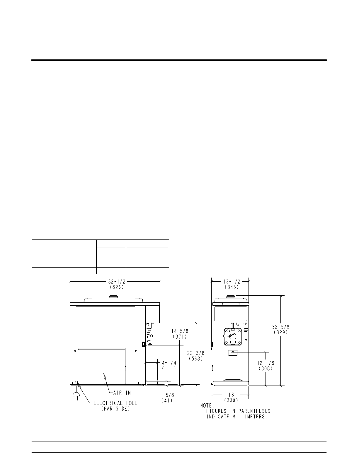
Clearance: Air Cooled Units
Minimum air clearances must be met to assure
adequate air flow for optimum performance. Failure
to allow for adequate clearance can reduce the
refrigeration capacity of the freezer and possibly
cause damage to the compressor.
Standard 428 units require a minimum of 6” (152
mm) of clearance on both sides of the freezer. It is
recommended to place the rear of the unit against
the wall.
For Indoor Use Only: This unit is designed to
operate indoors, under normal ambient
temperatures of 70_ 75_F (21_ 24_C). The
freezer has successfully performed in high ambient
temperatures of 104_(40_C) at reduced capacities.
This unit must NOT be installed in an area
where a water jet or hose can be used. NEVER use
a water jet or hose to rinse or clean this unit. Using a
water jet or hose on or around this equipment may
result in electrocution to the user or damage to the
equipment.
This unit must be installed on a level
surface to avoid the hazard of tipping. Extreme care
should be taken in moving this equipment for any
reason.
Two or more people are required to safely move this
unit. Failure to comply may result in personal injury
or equipment damage.
Uncrate the machine. Inspect the unit for damage.
Report any damage to the Taylor factory
immediately.
This piece of equipment is made in the USA and has
USA sizes of hardware. All metric conversions are
approximate and vary in size.
Installer Safety
In all areas of the world, equipment should
be installed in accordance with existing local codes.
Please contact your local authorities if you have any
questions.
Care should be taken to ensure that all basic safety
practices are followed during the installation and
servicing activities related to the installation and
service of Taylor equipment.
SOnly authorized Taylor service personnel
should perform installation and repairs on
the equipment.
SCord Connected Units: Only Taylor
authorized service personnel may install a
plug on this unit.
SAuthorized service personnel should consult
OSHA Standard 29CFRI910.147 or the
applicable code of the local area for the
industry standards on lockout/tagout
procedures before beginning any installation
or repairs.
SAuthorized service personnel must ensure
that the proper PPE is available and worn
when required during installation and
service.
SAuthorized service personnel must remove
all metal jewelry, rings, and watches before
working on electrical equipment.
THIS UNIT HAS MANY SHARP EDGES
THAT CAN CAUSE SEVERE INJURIES.
Examples:
Sscraper blades
Scondenser fins

7
Model 428 Introduction
Electrical Connections
In the United States, this equipment is
intended to be installed in accordance with the
National Electrical Code (NEC), ANSI/NFPA
701987. The purpose of the NEC code is the
practical safeguarding of persons and property from
hazards arising from the use of electricity. This code
contains provisions considered necessary for safety.
In all other areas of the world, equipment should be
installed in accordance with the existing local codes.
Please contact your local authorities.
Each unit requires one power supply for each data
label on the unit. Check the data label(s) on the
freezer for branch circuit overcurrent protection or
fuse, circuit ampacity, and other electrical
specifications.
Refer to the wiring diagram provided inside of the
electrical box for proper power connections.
FOLLOW YOUR LOCAL ELECTRICAL CODES!
CAUTION: THIS EQUIPMENT MUST BE
PROPERLY GROUNDED! FAILURE TO DO SO
CAN RESULT IN SEVERE PERSONAL INJURY
FROM ELECTRICAL SHOCK!
Note: This unit is provided with an equipotential
grounding lug that is to be properly attached to
either the rear of the frame or the under side of the
base pan near the entry hole for incoming power, by
the authorized installer. The installation location is
marked by the equipotential bonding symbol (5021
of IEC 604171) on both the removable panel and
the equipment's frame, as well as on the diagram.
SDO NOT operate the freezer with larger
fuses than specified on the data label.
SStationary appliances which are not
equipped with a power cord and a plug or
another device to disconnect the appliance
from the power source, must have an
allpole disconnecting device with a contact
gap of at least 3 mm installed in the external
installation.
SAppliances that are permanently connected
to fixed wiring and for which leakage
currents may exceed 10 mA, particularly
when disconnected or not used for long
periods, or during initial installation, shall
have protective devices such as a GFI, to
protect against the leakage of current,
installed by the authorized personnel to the
local codes.
SSupply cords used with this unit shall be
oilresistant, sheathed flexible cable not
lighter than ordinary polychloroprene or
other equivalent synthetic
elastomersheathed cord (Code designation
60245 IEC 57) installed with the proper cord
anchorage to relieve conductors from strain,
including twisting, at the terminals and
protect the insulation of the conductors from
abrasion.
Failure to follow these instructions may result in
electrocution or damage to the machine.
Beater Rotation
Beater rotation must be clockwise as
viewed looking into the freezing cylinder.
Disconnect all power to the unit. Failure
to follow this instruction may result in electrocution.
To correct rotation on a singlephase unit, change
the leads inside the beater motor by following the
diagram printed on the motor label.

8
Introduction Model 428
120628
Refrigerant
In consideration of our environment, Taylor proudly
uses only earth friendly HFC refrigerants. The HFC
refrigerant used in this unit is R404A. This
refrigerant is generally considered nontoxic and
nonflammable, with an Ozone Depleting Potential
(ODP) of zero (0).
However, any gas under pressure is potentially
hazardous and must be handled with caution.
NEVER fill any refrigerant cylinder completely with
liquid. Filling the cylinder to approximately 80% will
allow for normal expansion.
Use only R134a refrigerant that conforms to
the AHI standard 700 specification. The use of any
other refrigerant may expose users and operators to
unexpected safety hazards.
Refrigerant liquid sprayed onto the skin may
cause serious damage to tissue. Keep eyes and skin
protected. If refrigerant burns should occur, flush
immediately with cold water. If burns are severe,
apply ice packs and contact a physician
immediately.
Taylor reminds technicians to be cautious of
government laws regarding refrigerant recovery,
recycling, and reclaiming systems. If you have any
questions regarding these laws, please contact the
factory Service Department.
WARNING: R404A refrigerant used in
conjunction with polyolester oils is extremely
moisture absorbent. When opening a refrigeration
system, the maximum time the system is open must
not exceed 15 minutes. Cap all open tubing to
prevent humid air or water from being absorbed by
the oil.
Environmental Notices
______________________________
In consideration of our environment, Taylor proudly
uses only earth friendly HFC refrigerants. The HFC
refrigerant used in this unit is R404A. This
refrigerant is generally considered nontoxic and
nonflammable, with an Ozone Depleting Potential
(ODP) of zero (0).
However, any gas under pressure is potentially
hazardous and must be handled with caution.
If the crossed out wheeled bin symbol is
affixed to this product, it signifies that this product is
compliant with the EU Directive as well as other
similar legislation in effect after August 13, 2005.
Therefore, it must be collected separately after its
use is completed, and cannot be disposed as
unsorted municipal waste.
The user is responsible for returning the product to
the appropriate collection facility, as specified by
your local code.
For additional information regarding applicable local
laws, please contact the municipal facility and/or
local distributor.
NOISE LEVEL: Airborne noise emission does not
exceed 78 dB(A) when measured at a distance of
1.0 meter from the surface of the machine and at a
height of 1.6 meters from the floor.

9
Model 428 Systems and Controls
Section 2: Systems and Controls
SRefrigeration System
STorque Control

10
Systems and Controls Model 428
Refrigeration System

11
Model 428 Systems and Controls
Torque Control
Operation
When the unit is placed in the AUTO mode, the
beater motor is activated. After a three second
delay, the compressor starts. When the torque
sensor indicates that viscosity has been achieved, it
trips a microswitch and the compressor stops. The
beater motor continues to run for 20 seconds and
then stops.
If the torque sensor returns to the unsatisfied
position during the additional 20 seconds of beater
operation, the compressor will run again for an
additional 10 seconds (minimum) and will continue
until the torque sensor is satisfied. The beater motor
will run for 20 seconds.
If the torque sensor remains in the satisfied position
after a 7 minute cycle time has elapsed, the
refrigeration system will reactivate for 12 seconds or
until viscosity is satisfied.
Features
Mix Low / Mix Out
The Taylor Model 428 is equipped with a mix low /
mix out function. When the mix supply is low, the
sensor activates the MIX LOW light to indicate a
need for mix replenishment. When a mix out
condition is detected, the sensor activates the MIX
OUT light. The beater motor and compressor are
disabled at the completion of the draw.
Once the mix supply has been replenished, there is
a 30 second delay before the refrigeration system
continues.
Protection Fuse
There is an external fuse located on the control
board. The fuse protects the transformer from
damage in the event that the secondary side of the
board becomes shorted. When the fuse is open
(blown), all board functions are interrupted. The fuse
must then be replaced.

12
Systems and Controls Model 428
Notes:

13
Model 428 Troubleshooting
Section 3: Troubleshooting
SGeneral Troubleshooting Guide
SElectrical Troubleshooting Guide
STroubleshooting Torque Components

14
Troubleshooting Model 428
General Troubleshooting Guide
PROBLEM PROBABLE CAUSE REMEDY
1. No freezer operation with power
switch in the AUTO position.
a. Unit unplugged. a. Plug main power cord in the wall
receptacle.
b. Fuse blown or circuit breaker in the
OFF position.
b. Replace the fuse or place breaker
in the ON position.
c. The beater motor is out on reset. c. Place the control switch in the OFF
position and press the reset button
firmly. Place the power switch in
the WASH position and observe
the freezer's performance. Resume
normal operation.
2. With the power switch in the
AUTO position, the beater motor
runs, but the compressor does
not operate.
a. Tripped internal overload in the
compressor.
a. Allow the internal overload to cool.
Check for high head pressure,
refrigerant overcharge, stuck
pistons, or tight bearings.
b. Compressor is burned out. b. Replace the compressor.
c. Compressor is improperly wired. c. Check wiring against diagram on
compressor.
d. Low line voltage. d. Check the line voltage at terminal
block. Locate cause of voltage
drop.
e. Single‐phasing compressor
contactor.
e. Replace the compressor contactor.
3. Unit short cycles. a. Cycling on high pressure cut‐out.
Cut in: 404A: 340 PSI (2,344 kPa.)
Cut out: 404A: 440 PSI (3,034 kPa.)
a. Check the water supply (water‐
cooled units only) and make sure
the condenser is clean. Check for
potential refrigerant overcharge.
4. Compressor hums intermittently,
but will not start. Cycling on
overload.
a. Compressor is improperly wired. a. Check wiring against the diagram.
b. Low line voltage. b. Check the main line voltage and
locate voltage drop.
c. Relay contacts not closing. c. Check by operating manually.
Replace defective relay.
5. Product too stiff. a. Viscosity control is set too high. a. See the Torque Control section to
reset the control.
b. Torque Assembly incorrectly
assembled.
b. See the Troubleshooting Torque
Components section.
c. Inadequate mix in the hopper. c. Fill hopper with mix.
6. Product too soft. a. Viscosity control is set too low. a. See the Torque Control section to
reset the control.
7. Head pressure too low. a. Shortage of refrigerant. a. Locate and repair the leak.
Recover the refrigerant, evacuate,
and charge the system.
b. Water valve stuck open (water
cooled unit).
b. Clear or replace the valve.

15
Model 428 Troubleshooting
PROBLEM PROBABLE CAUSE REMEDY
8. Hot liquid line. a. Shortage of refrigerant. a. Repair leak and recharge system.
9. Frosted liquid line. a. Restricted dryer or tubing. a. Replace or remove restrictions.
10. No product being dispensed. a. Control switch is in the OFF position. a. Place the control switch in the
AUTO position.
b. Freeze‐up in the mix feed tube. b. Adjust hopper temperature by
readjusting the E.P.R. pressure.
c. Beater motor is out on reset. c. Place the control switch in the OFF
position and press the reset button
firmly. Place the power switch in
the WASH position and observe
the freezer's performance. Resume
normal operation.
d. Incorrect beater rotation. (Rotation
should be clockwise when viewed
from the front of the unit.)
d. Reverse any two of the three
incoming power lines (three phase
units only). For single phase units,
the motor must be rewired
according to the instructions on the
motor.
e. Circuit breaker out. e. Check breaker or fuse.
f. Faulty draw switch. f. Repair or replace switch.
g. Inadequate mix in the hopper. g. Fill the hopper with mix.
11. Scored freezing cylinder walls. a. Missing or worn front bearing on the
freezer door.
a. Install or replace front bearing.
b. Bent beater assembly. b. Replace beater and correct the
cause of insufficient mix in the
freezing cylinder.
12. Product not feeding into the
freezing cylinder.
a. Inadequate mix in the hopper. a. Fill the hopper with mix.
b. Freeze‐up in the mix inlet hole. b. Adjust hopper temperature.
13. Drive shaft stuck in the drive
coupling.
a. Mix and lubricant collected in the
drive coupling.
a. Brush clean rear shell bearing area
regularly.
b. Rounded corners of the drive shaft,
coupling, or both.
b. Replace worn component(s).
14. Excessive mix leakage through
the rear of the unit into the drip
pan.
a. Worn or missing drive shaft boot
seal.
a. Replace boot seal.
b. Inadequate lubrication of the drive
shaft boot seal.
b. Lubricate the boot seal according
to the Operator's Manual.
c. Worn rear shell bearing. c. Replace bearing.
d. Drive shaft works forward. d. Check gear alignment and scraper
blades. Make sure the beater is not
bent.
e. Wrong type of lubricant being used. e. Use lubricants recommended in the
Operator's Manual.

16
Troubleshooting Model 428
PROBLEM PROBABLE CAUSE REMEDY
15. Beater assembly works forward. a. Refrigerant shortage. a. Locate and repair leak.
b. Rear bearing unit is out of alignment. b. Align rear bearing unit.
16. Freezer door works loose. a. Handscrews are not tightly installed
or are damaged.
a. Tighten or replace handscrews.
b. Beater assembly works forward. b. See previous problem.
17. Low overrun. a. Bad scraper blades. a. Replace blades.
b. Mix feed tube is not installed. b. Install feed tube according to
instructions in the Operator's
Manual.
c. Beater rotates continually. c. Check for electrical short or faulty
power switch.
d. Long “ON" cycles. d. Make sure there is sufficient mix in
the hopper and that the condenser
is clean. Check the refrigerant
charge.
18. Leaking draw valve. a. Improper lubrication. a. Lubricate the draw valve according
to instructions in the Operator's
Manual.
b. Worn or nicked o‐rings on valve. b. Replace o‐rings.
c. Wrong lubricant being used. c. Use lubricants recommended in the
Operator's Manual.
19. Mix in the hopper is too cold. a. Temperature is out of adjustment. a. Adjust E.P.R. valve.
20. Mix in the hopper is too warm. a. Temperature is out of adjustment. a. Adjust E.P.R. valve.
b. Warm mix has been put in the
hopper.
b. Mix added to the hopper should be
below 40_F (4_C)
c. Hopper cover not in position. c. Install cover properly.
21. Compressor runs too long or
continuously.
a. Low refrigerant charge. a. Locate and repair the refrigerant
leak.
b. Worn or missing scraper blades. b. Replace scraper blades.
c. Inadequate air clearance. c. Provide adequate air clearance.
d. Incorrect beater rotation. d. Rotation should be counter‐
clockwise.
e. Faulty expansion valve. e. Replace valve.
f. Dirty or faulty fan assembly. f. Clean, repair or replace the fan
assembly.
Other manuals for 428
3
Table of contents
Other Taylor Freezer manuals
Popular Freezer manuals by other brands

Brandt
Brandt TA 110 NE operating instructions

Blizzard
Blizzard BR1SS Installation, operation & maintenance manual

Scotsman
Scotsman cCool 37FF installation instructions

Russell Hobbs
Russell Hobbs RH115 instruction manual

Frigidaire
Frigidaire FFC07C2CW0 Factory parts catalog

Haier
Haier DW-86L338J user manual

Zanussi
Zanussi ZFC233 Instruction booklet

AEG
AEG SCB618F6TS user manual

Arizona
Arizona SlimKool SK45AA owner's manual

Home
Home HME030366N manual

Baltimore Aircoil Company
Baltimore Aircoil Company S3000E Operating and maintenance instructions

Frigidaire
Frigidaire CHEST FREEZER FCFH 103 BW OPERATING AND INSTALLATION Manual