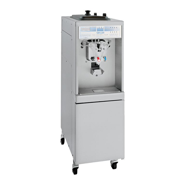
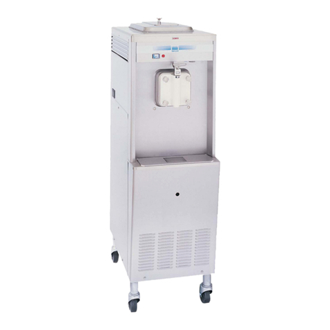
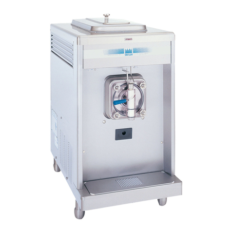
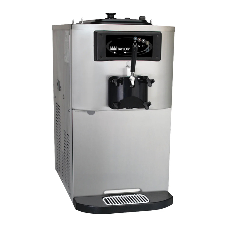
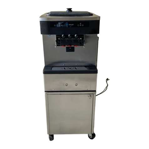
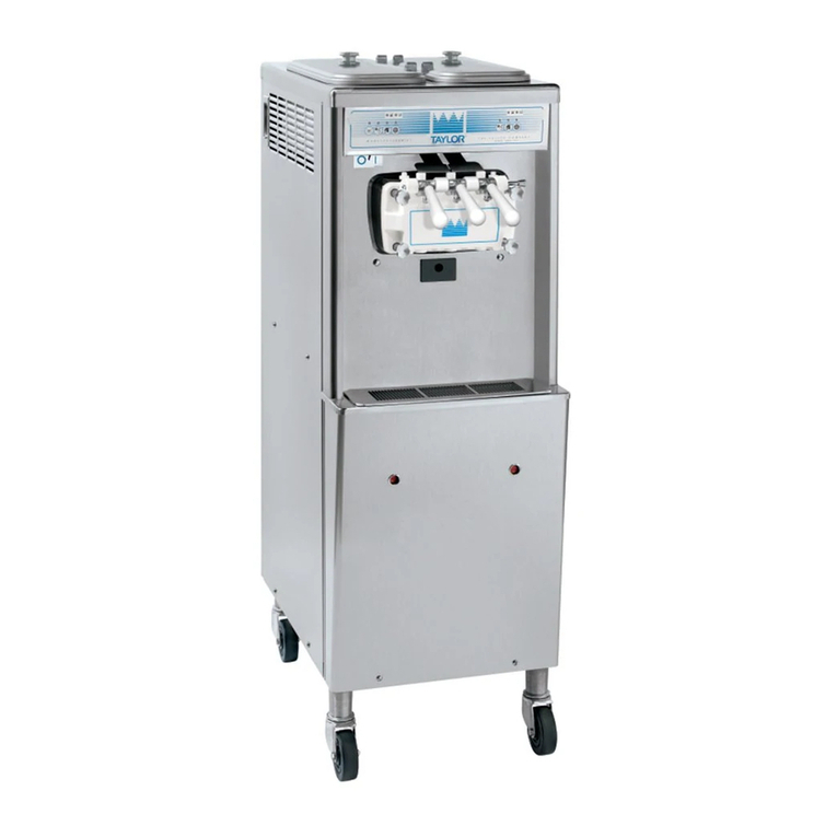
Taylor C712 User manual

SERVICE
MANUAL
Model C712 & C713
Soft Serve Freezers
6/15/05 (Original Publication)
(Updated 7/31/2018)
Original Service Instructions
062179-S

CAUTION: Information in this manual is intended to be used by authorized Taylor service technicians only.
Note: Continuing research results in steady improvements; therefore, information in this manual is subject
to change without notice.
Note: Only instructions originating from the factory or its authorized translation representative(s) are
considered to be the original set of instructions.
© June, 2005 Taylor Company
(Updated 7/31/2018)
062179-S
Any unauthorized reproduction, disclosure, or distribution of copies by any person of any portion of this work may be
a violation of Copyright Law of the United States of America and other countries, could result in the awarding of
Statutory Damages of up to $250,000 (17 USC 504) for infringement, and may result in further civil and criminal
penalties.
All rights reserved.
Taylor Company
750 N. Blackhawk Blvd.
Rockton, IL 61072

Table of Contents
062179-S i
Section 1: Introduction
Safety . . . . . . . . . . . . . . . . . . . . . . . . . . . . . . . . . . . . . . . . . . . . . . . . . . . . . . . . . . . . . . 1-2
Model C712 Specifications . . . . . . . . . . . . . . . . . . . . . . . . . . . . . . . . . . . . . . . . . . . . . . 1-4
Model C713 Specifications . . . . . . . . . . . . . . . . . . . . . . . . . . . . . . . . . . . . . . . . . . . . . . 1-6
Running Specifications . . . . . . . . . . . . . . . . . . . . . . . . . . . . . . . . . . . . . . . . . . . . . . . . . 1-8
General Installation Instructions . . . . . . . . . . . . . . . . . . . . . . . . . . . . . . . . . . . . . . . . . . 1-9
Environmental Notices . . . . . . . . . . . . . . . . . . . . . . . . . . . . . . . . . . . . . . . . . . . . . . . . 1-13
User Interface . . . . . . . . . . . . . . . . . . . . . . . . . . . . . . . . . . . . . . . . . . . . . . . . . . . . . . . 1-15
Section 2: Controls
Universal Control Programming . . . . . . . . . . . . . . . . . . . . . . . . . . . . . . . . . . . . . . . . . . 2-2
Power Interrupt . . . . . . . . . . . . . . . . . . . . . . . . . . . . . . . . . . . . . . . . . . . . . . . . . . . . . . 2-13
Pump Operation . . . . . . . . . . . . . . . . . . . . . . . . . . . . . . . . . . . . . . . . . . . . . . . . . . . . . 2-14
Timers . . . . . . . . . . . . . . . . . . . . . . . . . . . . . . . . . . . . . . . . . . . . . . . . . . . . . . . . . . . . .2-15
Beater Stir Cycles . . . . . . . . . . . . . . . . . . . . . . . . . . . . . . . . . . . . . . . . . . . . . . . . . . . . 2-16
Setting Viscosity . . . . . . . . . . . . . . . . . . . . . . . . . . . . . . . . . . . . . . . . . . . . . . . . . . . . . 2-17
Jumper Pin Charts . . . . . . . . . . . . . . . . . . . . . . . . . . . . . . . . . . . . . . . . . . . . . . . . . . . 2-18
Control Overview - UVC4 . . . . . . . . . . . . . . . . . . . . . . . . . . . . . . . . . . . . . . . . . . . . . . 2-20
Universal Control Board - UVC4 . . . . . . . . . . . . . . . . . . . . . . . . . . . . . . . . . . . . . . . . . 2-21
C712/C713 UVC4 Update Instructions . . . . . . . . . . . . . . . . . . . . . . . . . . . . . . . . . . . . 2-25
Refrigeration Schematic . . . . . . . . . . . . . . . . . . . . . . . . . . . . . . . . . . . . . . . . . . . . . . . 2-26
Refrigeration System Components . . . . . . . . . . . . . . . . . . . . . . . . . . . . . . . . . . . . . . . 2-27
Section 3: Troubleshooting
General Troubleshooting Guide . . . . . . . . . . . . . . . . . . . . . . . . . . . . . . . . . . . . . . . . . . 3-2
Electrical Troubleshooting Guide . . . . . . . . . . . . . . . . . . . . . . . . . . . . . . . . . . . . . . . . . 3-5
C712/C713 Electrical Troubleshooting Guide. . . . . . . . . . . . . . . . . . . . . . . . . . . . . . . . 3-6
Pump Style Freezer Troubleshooting . . . . . . . . . . . . . . . . . . . . . . . . . . . . . . . . . . . . . . 3-7
Bacteria Troubleshooting . . . . . . . . . . . . . . . . . . . . . . . . . . . . . . . . . . . . . . . . . . . . . . . 3-8
Section 4: Parts
Parts Warranty Explanation . . . . . . . . . . . . . . . . . . . . . . . . . . . . . . . . . . . . . . . . . . . . . 4-2
Model C712 Exploded View . . . . . . . . . . . . . . . . . . . . . . . . . . . . . . . . . . . . . . . . . . . . . 4-3
Operator Parts (Model C712) . . . . . . . . . . . . . . . . . . . . . . . . . . . . . . . . . . . . . . . . . . . . 4-6
Model C713 Exploded View . . . . . . . . . . . . . . . . . . . . . . . . . . . . . . . . . . . . . . . . . . . . . 4-8
Operator Parts (Model C713) . . . . . . . . . . . . . . . . . . . . . . . . . . . . . . . . . . . . . . . . . . . 4-11
Control A. - X67560-27 (Model C712). . . . . . . . . . . . . . . . . . . . . . . . . . . . . . . . . . . . . 4-13
Control A. - X67561-27-(Model C713) . . . . . . . . . . . . . . . . . . . . . . . . . . . . . . . . . . . . 4-15
Box A.-Cap & Relay - X6540227SP - (Model C712 & C713/Bristol). . . . . . . . . . . . . . 4-17
Box A.-Cap & Relay - X81081-27 (Model C713/Copeland) . . . . . . . . . . . . . . . . . . . . 4-18
Pump A.-Mix Simplified - X57029- (Model C712) . . . . . . . . . . . . . . . . . . . . . . . . . . . . 4-19
Door and Beater Assembly (Model C712) . . . . . . . . . . . . . . . . . . . . . . . . . . . . . . . . . 4-20

ii 062179-S
Table of Contents
Door and Beater Assembly (Model C713) . . . . . . . . . . . . . . . . . . . . . . . . . . . . . . . . . 4-21
Plate A.-Dec (Model C712). . . . . . . . . . . . . . . . . . . . . . . . . . . . . . . . . . . . . . . . . . . . . 4-22
Plate A.-Dec (Model C713). . . . . . . . . . . . . . . . . . . . . . . . . . . . . . . . . . . . . . . . . . . . . 4-23
Rail-Syrup - X63883-27 (Optional) . . . . . . . . . . . . . . . . . . . . . . . . . . . . . . . . . . . . . . . 4-24
Switch A.-Dual Lever - X69838 (Model C712 & C713). . . . . . . . . . . . . . . . . . . . . . . . 4-25
Actuator A.-Draw Switch - X69835 (Model C712 & C713) . . . . . . . . . . . . . . . . . . . . . 4-26
Blower A. X53725-27 (Model C712 & C713) . . . . . . . . . . . . . . . . . . . . . . . . . . . . . . . 4-27
Condenser A. - X68077-27G (Model C712 & C713) . . . . . . . . . . . . . . . . . . . . . . . . . 4-28
Accessories . . . . . . . . . . . . . . . . . . . . . . . . . . . . . . . . . . . . . . . . . . . . . . . . . . . . . . . . 4-29
Brushes (Model C712 & C713). . . . . . . . . . . . . . . . . . . . . . . . . . . . . . . . . . . . . . . . . . 4-30
Section 5: Parts List
Section 6: Wiring Diagrams

1-2
INTRODUCTION
Models C712/C713 Introduction
1
Safety
We at Taylor Company are committed to manufacturing
safe operating and serviceable machines. The many
built-in safety features that are part of all Taylor machines
are aimed at protecting operators and trained service
technicians alike.
This manual is intended exclusively for Taylor authorized
service personnel.
Per IEC 60335-1 and its part 2 standards, “This
appliance is to be used only by trained personnel. It is not
intended for use by children or people with reduced
physical, sensory, or mental capabilities, or lack of
experience and knowledge, unless given supervision or
instruction concerning the use of the appliance by a
person responsible for their safety.”
NOTICE! This manual is intended exclusively
for authorized Taylor service personnel.
CAUTION! DO NOT attempt to run the machine
unless you have been properly trained to do so. Failure
to do so can result in personal injury or machine damage.
WARNING! This machine must be properly
grounded! DO NOT operate this machine unless it is
properly grounded and all service panels and access
doors are restrained with screws. Failure to do so can
result in severe personal injury from electrical shock!
WARNING! Avoid injury.
•DO NOT attempt any repairs unless the main
power supply to the machine has been
disconnected.
•DO NOT operate the machine with larger fuses
than specified on the data label.
• Stationary machines which are not equipped
with a power cord and plug or other device to
disconnect the machine from the power source
must have an all-pole disconnecting device with
a contact gap of at least 0.125 in. (3 mm)
installed in the external installation.
• Machines that are permanently connected to
fixed wiring and for which leakage currents may
exceed 10 mA, particularly when disconnected,
not used for long periods, or during initial
installation, shall have protective devices to
protect against the leakage of current, such as a
GFI, and be installed by authorized personnel to
the local codes.
• Supply cords used with this machine shall be
oil-resistant, sheathed flexible cable, not lighter
than ordinary polychloroprene or other
equivalent synthetic elastomer-sheathed cord
(code designation 60245 IEC 57) installed with
the proper cord anchorage to relieve conductors
from strain, including twisting, at the terminals
and protect the insulation of the conductors
from abrasion.
•For Cord-Connected Machines: Only
authorized Taylor service technicians may
install a plug on this machine.
Failure to follow these instructions may result in
electrocution or damage to the machine.
IMPORTANT! This machine is provided with
an equipotential grounding lug that is to be properly
attached to the rear of the frame by the authorized
installer. The installation location is marked by the
equipotential bonding symbol (5021 of IEC 60417-1) on
the removable panel and the frame.

!

INTRODUCTION
1-3
Models C712/C713
Introduction
1
CAUTION! DO NOT remove the machine door
or any internal operating parts (examples: beater, scraper
blades, etc.) unless all control switches are in the OFF
position. Failure to follow these instructions may result in
severe personal injury from hazardous moving parts.
WARNING! This machine has many sharp
edges that can cause severe injuries.
Examples:
• Scraper blades
• Condenser fins
• Cup/cone dispenser (if applicable)
CAUTION! This machine must be installed on
a level surface to avoid the hazard of tipping. Extreme
care should be taken in moving this machine for any
reason. Two or more persons are required to safely move
this machine. Failure to comply may result in personal
injury or machine damage.
WARNING! Only install this machine in a
location where its use and maintenance is restricted to
trained personnel. Failure to comply may result in
personal injury.
WARNING! This machine must NOT be
installed in an area where a water jet or hose can be
used. NEVER use a water jet or hose to rinse or clean
the machine. Failure to follow this instruction may result
in electrocution.
NOTICE! Cleaning and sanitizing schedules
are governed by your federal, state, or local regulatory
agencies and must be followed accordingly. Please see
the cleaning section of this manual for the proper proce-
dure to clean this machine.
Important! Authorized service personnel must ensure
that the proper personal protective equipment (PPE) is
available and worn when required during installation and
service.
IMPORTANT! Access to the service area of
the machine is restricted to persons having knowledge
and practical experience with the machine, in particular
as far as safety and hygiene are concerned.
!
!
!

1-4
INTRODUCTION
Models C712/C713 Introduction
1
Model C712 Specifications
Freezing Cylinder
Two, 3.4 qt. (3.2 L)
Mix Hopper
Two, 20 qt. (18.9 L)
Beater Motor
Two, 1.5 hp
Refrigeration Machine
Two, approximately 9,500 BTU/hr compressors
Refrigerant R404A.
Electrical
Table 1-1
This machine may be manufactured in other electrical
characteristics. Refer to the local Taylor distributor for
availability. (For exact electrical information, always see
the data label of the machine.)
Air-Cooled
Clearance: A minimum of 3 in. (76 mm) is required
around all sides. Install the deflector provided to prevent
recirculation of warm air.
Water-Cooled
Water inlet and drain connections under the side of the
base, 1/2 in. FPT.
Dimensions
Width: 25-7/16 in. (646 mm)
Height: 60 in. (1524 mm)
Depth: 36-3/16 in. (919 mm)
Floor Clearance*: 4-3/4 in. (121 mm)
*Mounted on standard casters
Approximate Weights
Net: 777 lbs. (352 kgs)
Crated: 855 lbs. (388 kgs)
Volume: 68.4 cu. ft. (1.94 cu m)
Electrical Maximum
Fuse Size
Minimum
Circuit
Ampacity
Left Right Left Right
208-230/60/1 Air 35 35 27 25
208-230/60/1 Air, Syrup 40 35 28 25
208-230/60/1 Water 35 35 26 25
208-230/60/3 Air 25 20 19 17
208-230/60/3 Water 25 20 18 17
220-240/50/1 Water 30 25 22 20
380-415/50/3N~Air 12 10 11 9

INTRODUCTION
1-5
Models C712/C713
Introduction
1
Figure 1-1

1-6
INTRODUCTION
Models C712/C713 Introduction
1
Model C713 Specifications
Freezing Cylinder
Two, 3.4 qt. (3.2 L)
Mix Hopper
Two, 20 qt. (18.9 L)
Beater Motor
Two, 1.5 hp
Refrigeration Machine
Two, approximately 9,500 BTU/hr compressors
Refrigerant R404A.
Electrical
Table 1-2
This machine may be manufactured in other electrical
characteristics. Refer to the local Taylor distributor for
availability. (For exact electrical information, always see
the data label of the machine.)
Air-Cooled
Clearance: A minimum of 3 in. (76 mm) is required
around all sides. Install the deflector provided to prevent
recirculation of warm air.
Water-Cooled
Water inlet and drain connections under the side of the
base, 1/2 in. FPT.
Dimensions
Width: 25-7/16 in. (646 mm)
Height: 60 in. (1524 mm)
Depth: 36-3/16 in. (919 mm)
Floor Clearance*: 4-3/4 in. (121 mm)
*Mounted on standard casters
Approximate Weights
Net: 733 lbs. (333 kgs)
Crated: 810 lbs. (367 kgs)
Volume: 67.5 cu. ft. (1.91 cu m)
Electrical Maximum
Fuse Size
Minimum
Circuit
Ampacity
Left Right Left Right
208-230/60/1 Air 35 35 25 23
208-230/60/1 Air, Syrup 35 35 26 23
208-230/60/1 Water 35 35 25 23
208-230/60/3 Air 25 25 19 17
208-230/60/3 Water 20 20 17 15
220-240/50/1 Water 25 25 21 19
380-415/50/3N~Air 12 10 9 8
Other manuals for C712
3
This manual suits for next models
1
Table of contents
Other Taylor Freezer manuals

Taylor
Taylor 340 User manual

Taylor
Taylor 161 User manual

Taylor
Taylor 342 Tim Hortons User manual

Taylor
Taylor Taylormate 150 User manual

Taylor
Taylor Model C043 User manual

Taylor
Taylor 142 User manual

Taylor
Taylor 60 User manual

Taylor
Taylor 390 User manual

Taylor
Taylor Model C043 User manual

Taylor
Taylor 358 User manual

Taylor
Taylor H60 User manual

Taylor
Taylor C606 User manual

Taylor
Taylor Taylormate 152 User manual

Taylor
Taylor C707 User manual

Taylor
Taylor PH61 User manual

Taylor
Taylor C709 User manual

Taylor
Taylor 345 User manual

Taylor
Taylor 632 User manual

Taylor
Taylor 750 User manual

Taylor
Taylor Horizon 8756 User manual