TB Wood's Form-Flex HH Series User manual

WARNING: Cancer and Reproductive Harm - www.P65Warnings.ca.gov
Form-Flex® Single Flex Coupling
Type HH & FH All Sizes
Installation Instructions
P-5004-TBW
FORM 1174
Form 1174
Single Flex Coupling
Installation and Maintenance Instructions
TYPE HH & FH ALL SIZES
(HH)
Fig. 1
Fig. 2
(FH)
PARTS LIST
1. NUT (8)
2. WASHER (8)
3. FLEX ELEMENT (1)
4. BOLT (8)
5. HUB (2)
PARTS LIST
1. ADAPTER (1)
2. NUT (8)
3. WASHER (8)
4. FLEX ELEMENT (1)
5. BOLT (8)
6. HUB (1)
Proper care in installing and aligning will permit couplings to operate to full capacity, compensate for misalignment, and
provide very good service life.
1. Inspect shafts and hubs bores and make sure they are free from burrs. Check for the proper t of the keys to the shafts
and hubs.
2. Fit the couplings hub(s) so that the shaft end(s) is/are ush with the machined face of the ange. If the hub is bored for
interference t, the hubs should be heated then quickly positioned on the shaft. Do Not spot heat or heat above 300°F
as it may cause distortion.
3. Move the equipment to be connected into position. Set the gap to the required “D” dimension. See Fig. 1 or 2.
Form-Flex ®
P-5004-TBW Form 1174 8/18
www.tbwoods.com
440 North Fifth Avenue
Chambersburg, PA 17201 - USA
888-829-6637 • 717-264-7161
ASSEMBLY
4. Assemble the coupling using gures 1 or 2 as a guide. Do not drive or force bolts into position. All nuts must be tight-
ened to the value shown in Table I with lightly oiled threads.
TABLE I (Lightly oiled threads)
ALIGNMENT
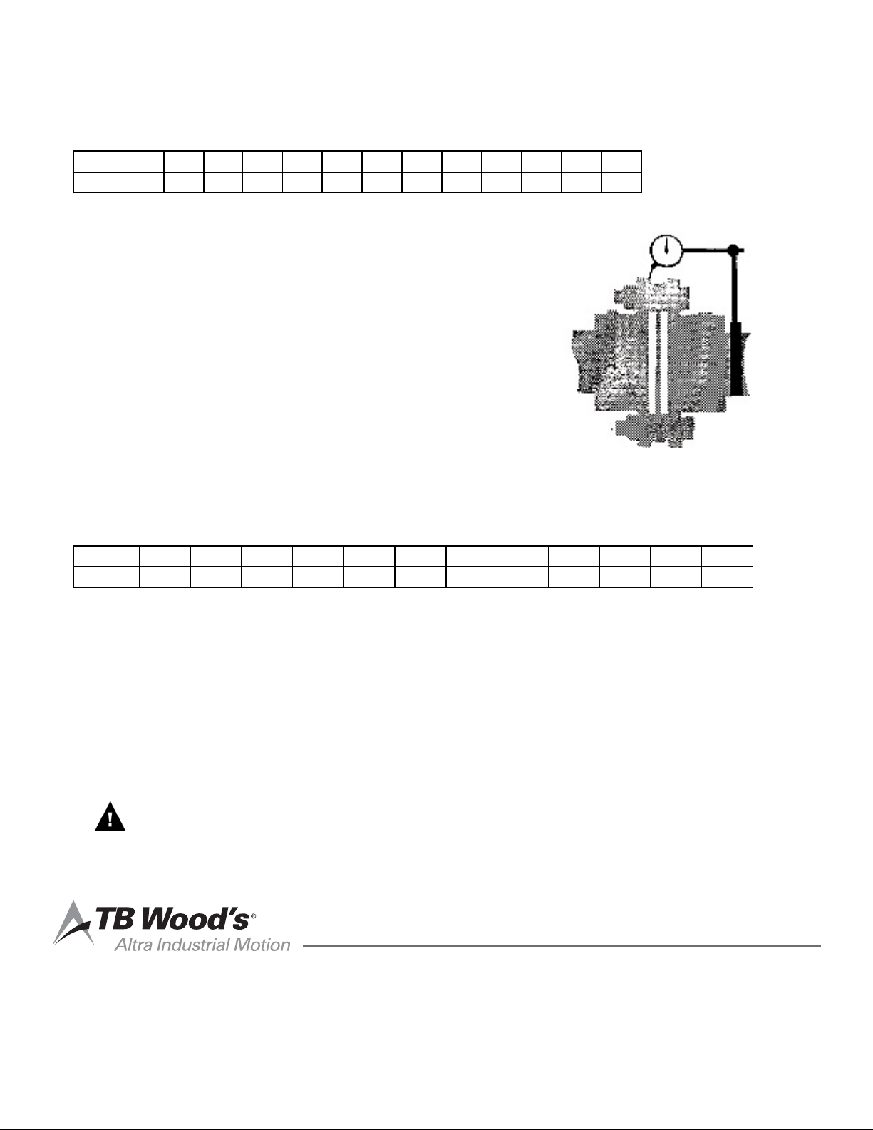
5. After preliminary alignment and complete assembly, secure a dial
indicator to one hub as shown in gure (3) and indicate face of the
other hub or adapter as shown. Indicator mounting is optional.
6. Rotate the coupling to nd minimum indicator reading. Set the
indicator for zero reading.
7. Again, rotate the coupling 360° to check misalignment.
8. Adjust position of connected equipment until indicator reading is
within the allowable variation shown in Table II.
Fig. 3
TABLE II Total indicator reading inches.
IMPORTANT: To ensure unlimited life re-check alignment after a short period (one to two hours)
of actual running. At this time also re-torque bolts and nuts to values to Table I. If
equipment is portable this should be done each time the equipment is moved.
WARNING
ROTATING EQUIPMENT IS POTENTIALLY
DANGEROUS AND MUST BE PROPERLY
GUARDED. THE USER SHOULD COMPLY
WITH APPLICABLE SAFETY CODES IN
ACCORDANCE TO OSHA STANDARDS.
TB Wood’s Incorporated
440 North Fifth Avenue
Chambersburg, Pennsylvania 17201-1778
Telephone: 888-TBWOODS or 717-264-7161
FAX: 717-264-6420
Website: www.tbwoods.com
Form 1174
REPLACEMENT PARTS
To order replacement parts it is necessary to furnish the complete part number(s) and the required part(s). Order
must be placed with your distributor.
SIZE 31 35 42 45 50 55 60 70 75 80 85 92
FT-LB 10% 40 70 125 150 210 320 450 575 830 1000 1400 1400
±
SIZE 31 35 42 45 50 55 60 70 75 80 85 92
TIR .004 .004 .005 .006 .006 .007 .008 .009 .010 .011 .012 .013
ASSEMBLY
4. Assemble the coupling using gures 1 or 2 as a guide. Do not drive or force bolts into position. All nuts must be tight-
ened to the value shown in Table I with lightly oiled threads.
TABLE I (Lightly oiled threads)
ALIGNMENT
5. After preliminary alignment and complete assembly, secure a dial
indicator to one hub as shown in gure (3) and indicate face of the
other hub or adapter as shown. Indicator mounting is optional.
6. Rotate the coupling to nd minimum indicator reading. Set the
indicator for zero reading.
7. Again, rotate the coupling 360° to check misalignment.
8. Adjust position of connected equipment until indicator reading is
within the allowable variation shown in Table II.
Fig. 3
TABLE II Total indicator reading inches.
IMPORTANT: To ensure unlimited life re-check alignment after a short period (one to two hours)
of actual running. At this time also re-torque bolts and nuts to values to Table I. If
equipment is portable this should be done each time the equipment is moved.
WARNING
ROTATING EQUIPMENT IS POTENTIALLY
DANGEROUS AND MUST BE PROPERLY
GUARDED. THE USER SHOULD COMPLY
WITH APPLICABLE SAFETY CODES IN
ACCORDANCE TO OSHA STANDARDS.
TB Wood’s Incorporated
440 North Fifth Avenue
Chambersburg, Pennsylvania 17201-1778
Telephone: 888-TBWOODS or 717-264-7161
FAX: 717-264-6420
Website: www.tbwoods.com
Form 1174
REPLACEMENT PARTS
To order replacement parts it is necessary to furnish the complete part number(s) and the required part(s). Order
must be placed with your distributor.
SIZE 31 35 42 45 50 55 60 70 75 80 85 92
FT-LB 10% 40 70 125 150 210 320 450 575 830 1000 1400 1400
±
SIZE 31 35 42 45 50 55 60 70 75 80 85 92
TIR .004 .004 .005 .006 .006 .007 .008 .009 .010 .011 .012 .013
This manual suits for next models
1
Table of contents
Popular Industrial Equipment manuals by other brands

Endress+Hauser
Endress+Hauser Proline t-mass 300 Special Documentation

Burkert
Burkert BBS-03 operating instructions

Siemens
Siemens SITOP UPS500S Ex operating instructions

SUHNER
SUHNER Sensornocken installation instructions

Husqvarna
Husqvarna 1-8DPF40 Operator's manual

Transforming Technologies
Transforming Technologies PTEC IN6430 instruction manual


ABB
ABB A255-L Assembly instructions

Hubbell
Hubbell RAFB4 Series installation instructions

Swagelok
Swagelok AHSU Set up and operating instructions

POMPE ROTOMEC
POMPE ROTOMEC ECOMIX E0 Series Use and maintenance manual

PERGO
PERGO SCHWAMMFIX POWER SPONGE 620P User & Safety Instructions

Fein
Fein VersaMAG VISE manual