Transforming Technologies PTEC IN6430 User manual

Model IN6430
Static Eliminators
Instruction Manual
Ionizing Air Gun
Model IN6430

Contents
1Description
IN6430 1
Features 1
Power Requirements 2
2Operation and Use
Environmental Conditions 2
Set-up and Placement 2
Mounting 3
Power and Gas Connection 3
3Maintenance
Periodic Maintenance 4
Cleaning Emitter Points 4
Emitter Point Replacement 5
Service 6
Troubleshooting 6
4 Specifications 7
5 Assembly and
Mounting Instructions 8
6Service and Warranty 12
7 IN6430 Line Drawing 13

Description
Ionizing Air Gun Model IN6430
The Model IN6430 68KHz AC ionizing air gun effec-
tively removes particle contamination, even on static sen-
sitive components The IN6430 easily connects to a com-
pressed air source and is compact and lightweight. Using
AC corona technology to make the air more conductive,
Ptec™ ionizers produce a balanced stream of positive and
negative air ions that never need calibration. The control-
ler connects to a clean dry air or nitrogen source and an
integrated disposable filter collects particles. The gun and
air hose are lightweight and easy to use.
About Ptec™ Technology
A specialized piezoelectric high voltage transformer
makes Ptec™ ionizers among the most reliable products
available. Ptec™ ionizers are designed to remain in bal-
ance and to alarm when the HV output affects perform-
ance. The model IN6430 ionizing air nozzle produces a
68KHz AC output of approximately 2200V and a continu-
ous stream of balanced air ions. Ionizers that use Ptec™
technology do not require calibration and only minimal
maintenance.
Features
On the gun of the IN6430 are two LEDs. The green
LED indicates that power is applied to the Ptec™ HV
transformers The red LED illuminates when an alarm con-
dition occurs. An on-off switch is provided on the controller
as well as a 100—240vac IEC input.
1

Features cont’d.
Complete point-of-use protection.
Rapidly decays static charges. (+1000V to 100V, < 2
sec. @ 6”, typical).
Excellent ion balance, 0 +30V.
Stable AC technology.
Ionization indicator light.
HV alarm (red) lights.
No periodic adjustments.
Durable, replaceable tungsten alloy emitter points.
Up to 75 PSI output, adjustable.
Optional filter.
Power Requirements
The Model IN6430 High Frequency AC ionizing air noz-
zle is internally powered by a DC switching power supply
that operates from 100-240 VAC 50/60 Hz IEC input. The
output of the supply is +24 VDC @ .5 AMP. Note: Ionizer
must be grounded.
Operation and Use
Environmental Conditions
The IN6430 can be operated in areas where humidity
is 20-70% RH (Non-condensing). Excess humidity may af-
fect ionizer performance. The temperature range for the
IN6430 is 65-78°F (18-25°C).
Set-up and Placement
Choose a location convenient to the work area and the air
supply. Determine if you will use the product with or without
an internal filter and attach the appropriate connector to the
hose assembly.
2

Mounting
No equipment or tools are necessary, except for
permanent mounting and air line. A permanent mounting
bracket, with screws for the controller, is included. See
mounting instructions.
Power and Gas Connection
Attach the IN6430 gun assembly to the controller. Af-
ter mounting the controller, attach the gas line. The
IN6430 comes with a 1/4” interchange connector and
alternative 1/4” quick release connector. Adjust oper-
ating pressure as required to maximum 75 psi.
Connect the IEC power cord to the controller and
plug it in an AC socket.
Make certain the outlet is grounded.
Turn the unit on and depress the trigger to start the
airflow and the corona process. The ionizer creates a
Caution
!
Do not use this ionizer in an explosive environ-
ment! Corona ionizers produce a weak plasma
that can cause ignition in explosive environ-
ments.
3
Caution
!
The IN6430 operates only with clean dry air
(CDA) or nitrogen (N2). Operator must provide
clean and filtered incoming gas to adequately
remove moisture, oil and particles from the
source supply.
Caution
!
The IN6430 is not designed to withstand high
air pressure. The product should be installed
with shutoff valve upstream. The output side of
the nozzle should always be at atmospheric pre-
seure.

continuous stream of positive and negative air ions
when activated.
The ionized airflow is directed through the nozzle tip
which feature OSHA relief holes. Charged objects in
the ionization area are rapidly neutralized .
A green light will illuminates to signal the IN6430 is
operating.
The red alarm indicator light illuminates in the event
of a problem with the high voltage power output.
Turn the power switch off when not in use for ex-
tended periods.
Maintenance
Periodic Maintenance
The only regular maintenance required for the
IN6430 is the periodic cleaning of the emitter point. Emit-
ter point cleaning affects the static decay ability of the
ionizer and is important for maintaining its optimal per-
formance.
Cleaning the emitter points
Contaminants will gradually accumulate on the tip
of the emitter points, depending in part, on frequency of
use. Periodic cleaning of the emitter points is necessary
to maintain the performance of the ionizer. If the emitter
points are dirty, clean them with a polyester or cotton
swab and IPA. Do not damage or loosen the emitter
points.
Caution
!
The only serviceable parts inside the ionizer are
the replaceable emitter points. Any unauthor-
ized service will void the warranty and may
result in additional repair fees.
4

Follow these instructions to clean the emitter point:
1. Turn off power and unplug ionizer.
2.
1.
Remove the output nozzle tip and ceramic insulator.
2. Moisten a swab in the IPA solution.
3. Swab or wipe the emitter point until it is free of
particles.
4. Make certain the emitter point is straight and undam-
aged.
5. Replace the output nozzle tip and insulator.
6. Make sure the emitter points are dry before powering the
ionizer again.
Emitter Point Replacement
The IN6430 uses tungsten alloy precision etched emit-
ter needles. Contact Transforming Technologies for infor-
mation about ordering replacement emitters. The part num-
ber for emitters is listed below:
Replacement part Part Number
IN6430 tungsten replacement emitters 22-6433
Because the IN6430 high voltage output is AC, emitter
erosion from the ionization process on the electrodes is
minimal. Unless physically broken or stressed, the IN6430
emitters should last the life of the ionizer.
Follow these instructions to remove the emitter points:
1. Turn off and disconnect the unit from the AC power.
2. Remove the output nozzle.
3. Unscrew the threaded emitter point using a needle nose
pliers.
4. Replace and tighten the new emitter using the same
tool. Do not over-tighten.
5

5. Make certain the emitter point is straight and undam-
aged.
6. Replace the output nozzle.
Assembling the Ionizing Gun
1. Determine if you will use the optional integrated filter
(FL0030). Screw the FA100 bypass into the gun/hose
assembly, if not using the filter. Screw the FL0030
and then the FA200 filter adapter into the gun/hose
assembly, if using the filter option.
2. Remove the filter cover from the controller.
3. Connect the gun/hose assembly to the controller. The
FA100 or FA200 must connect securely to the air
coupling inside the controller.
4. Connect the controller to the air supply using inter-
change connector or quick release connector.
Service
Ptec™ ionizers are reliable products with a long ser-
vice life. If you feel your unit is not operating properly,
turn off the unit and disconnect the power cord. Contact
Transforming Technologies’ Technical Support for repair
assistance.
Troubleshooting
The information below provides a reference for prob-
lems that may arise with your IN6430 ionizing air nozzle.
If you have other problems not covered below, please
contact Transforming Technologies’ Technical Support
for repair assistance
6

Problem Causes
Balance outside Emitter points are dirty, damaged
specifications. or not straight. Clean or replace
Alarm light activated Low HV output, call for repair
7
Specifications
Power Input AC 100V~240V, 50/60Hz
Power Outlet un-fused, 0.5A or 1.0A max.
Ion Emission AC, 68KHz
Balance +30 volts
Decay Time 1000V—100V, < 2 seconds @
12”
Temperature 66-78°F (19-25°C)
Humidity 20-60% RH (non-condensing
Air Pressure 20—75 PSI, CDA or N2
Indicators Power: Green LED, Alarm: Red
Controls On/off switch
Mounting Mounting holes on controller
Emitter Points Tungsten Alloy
Dimensions
Hand Unit 8.5"H x 4"W x 1"D, (21.6 x
10.2 x 2.5 cm)
Console 3.5"H x 6.25"W x 1.5"D, (8.9 x
15.8 x 3.8 cm)
Filter Option .01 micron filter (replaceable)*
*Note: Unit also may be operated without filter.
Weight
Hand Unit 12 oz. (.341 kg) with 9.5’ air
hose
Console 1 lb. (.45 kg)
Gas Input & Connection 20—75 psi, CDA or N2, 1/4” male
industrial interchange quick
disconnect or 1/4” quick release
tube fitting
Warranty 1-year limited warranty

Figure 1. Gun with FA100 (no filter) Figure 2. Gun with FA200 and FL0030
2. Standard Operation (no filter):
Insert one end of the filter bypass (FA100) with rubber washer
into hose assembly and twist clockwise. Twist clockwise until
tight. Assembled hose should look like figure 3.
Figure 3. Hose with FA100 (no filter)
Assembly
1. Overview: The IN6430 can be used with or without a filter at-
tachment. The product comes standard without the filter assembly
and uses the filter bypass unit (FA100) to connect the gun to the
console. The filter (FL0030) and filter assembly (FA200) are used
together when the filter is required and is purchased separately.
3. Filter Assembly: To attach filter, insert one end of the filter
with rubber washer into hose assembly and twist clockwise.
Place the Filter Assembly (FA200) with rubber washer on re-
maining end of filter and twist clockwise until tight. Assembled
hose should look like figure 5.
8
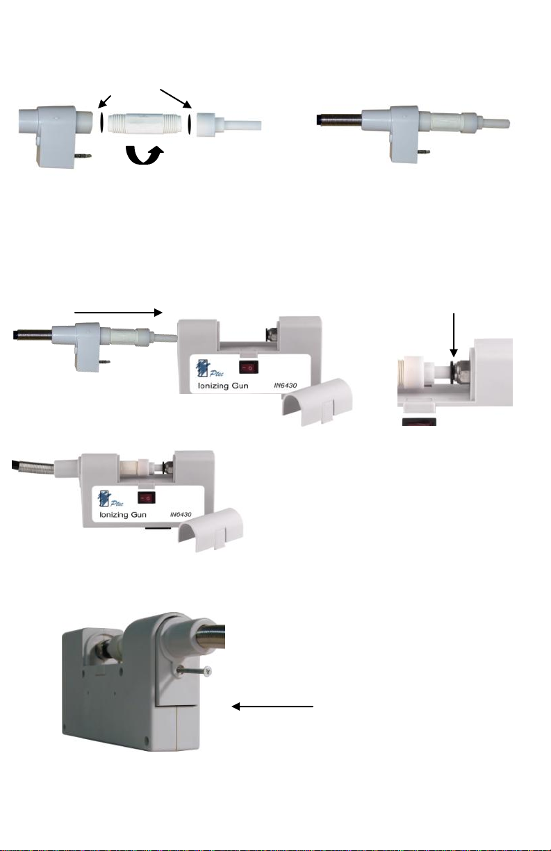
Assembly Cont.
Figure 4. Filter Assembly Figure 5. Filter Assembly Finished
Washers
5. Connect gun hose to base console.
Insert hose until the filter bypass unit (FA100) or the filter
assembly (FA200) locks into finger release button ( Figure
5.).
Figure 6. Finger
Release Button
Finger Release
Figure 7. Assembled Gun 6. Use locking screw to firmly
secure hose to base console.
Locking Screw
9
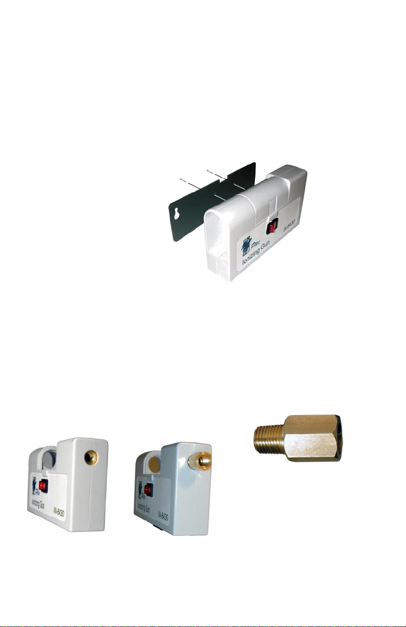
7. Mounting the gun: A mounting back plate and 2 screws
are included with the IN6430 . Mount to the IN6430 as pic-
tured. Then mount the back plate to the desired location.
8. Air attachment: Use Teflon tape with all pressurized
connections. Both finger quick release and industrial inter-
change connectors are provided.
Converter (included)
1/8 BSPT to 1/8 NPT Thread
Gun on the left with out Converter. Gun on the right with Converter
Mounting
10
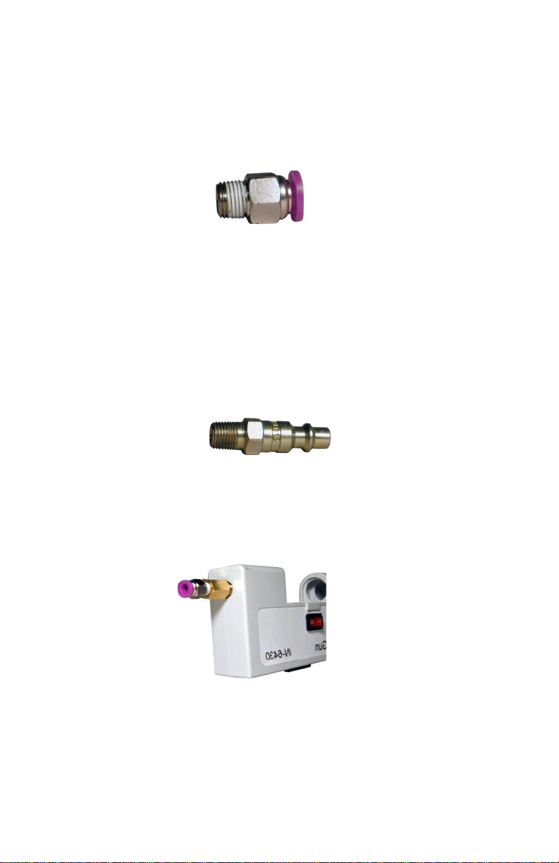
Industrial Interchange
(Included) 1/4 inlet, 1/8 NPT Thread
Option 2
Finger Quick Release
(Included) 1/4 inlet, 1/8 NPT Thread Size
Option 1
Gun with converter and quick release attachments
Air Inlet Options
11

Service and Warranty
Transforming Technologies, LLC provides a lim-
ited warranty for the Model IN6430 ionizing air noz-
zle. All new products are guaranteed to be free from
defects in material and workmanship for a period of
one (1) year from the date of shipment. Liability is
limited to servicing (after evaluating, repairing or re-
placing) any product returned to Transforming Tech-
nologies. The company does not warrant damage
due to misuse, neglect, alteration or accident. In no
event shall Transforming Technologies be liable for
collateral or consequential damages.
To receive service under warranty, please con-
tact Transforming Technologies Technical Support.
About Transforming Technologies
Since 1998, Transforming Technologies has
helped electronic manufacturing facilities to protect
their products and processes from the many serious
problems associated with static electricity.
Transforming Technologies offers a wide range
of unique and outstanding products to detect, pro-
tect, eliminate and monitor electrostatic charges.
Our products are integral components of an effec-
tive static control program.
12
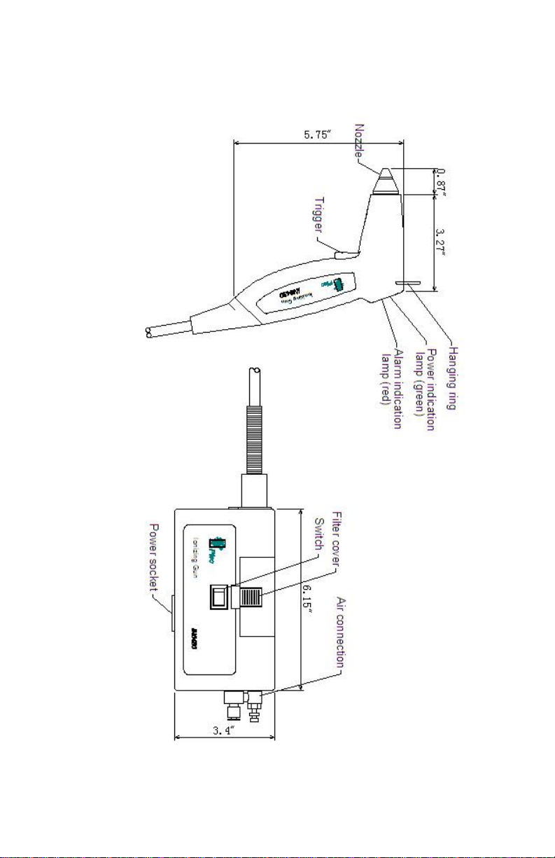
IN6430 Line Drawing
13

3719 King Rd | Toledo, OH 43617 | P: 419-841-9552 | F: 419-841-3241 | info@transforming-technologies.com
Table of contents
Other Transforming Technologies Industrial Equipment manuals

Popular Industrial Equipment manuals by other brands


KAUP
KAUP 3T458P operating manual

ABB
ABB HT607822 Operation manual

ABB
ABB HT844006 Operation manual

Alpha Technologies
Alpha Technologies Cordex 24-3.1kW Installation & operation manual

Giacomini
Giacomini K470H Series quick start guide

PAW
PAW SolarBloC midi Premium Assembly, installation and operation instructions