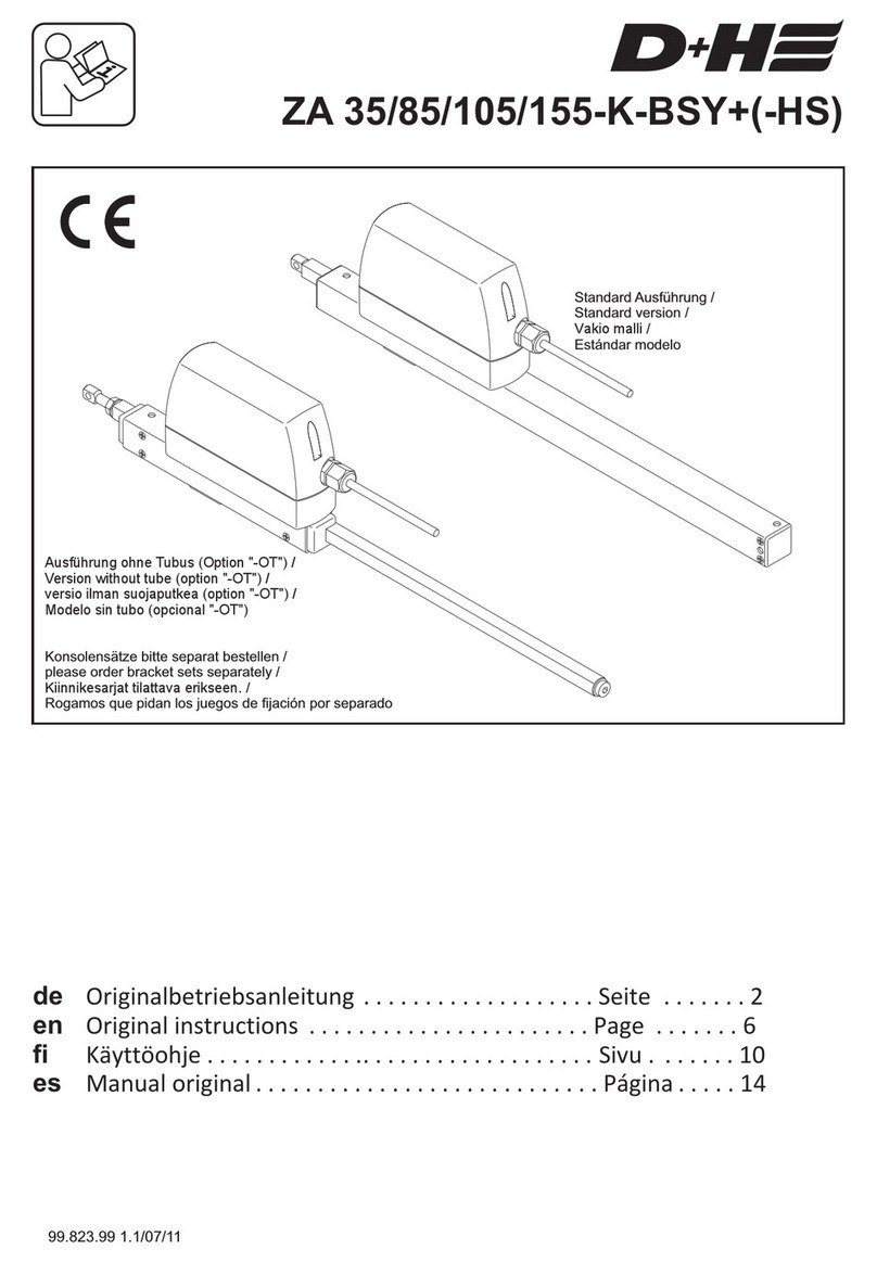
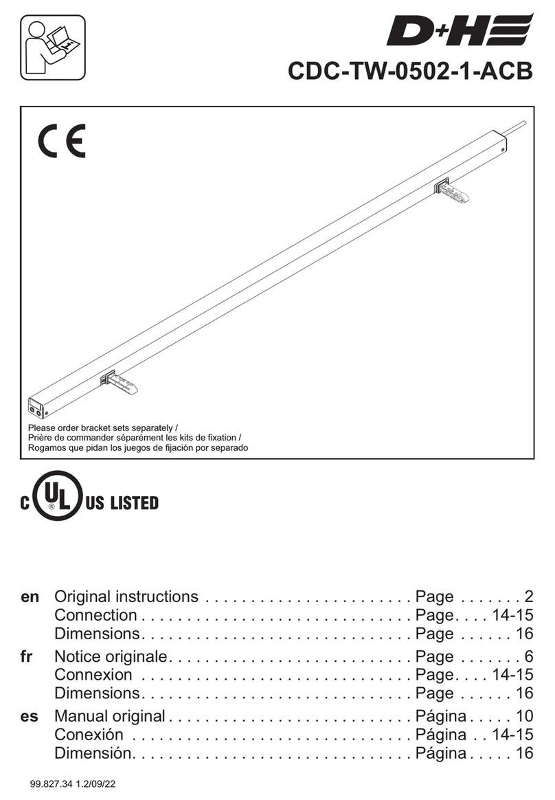
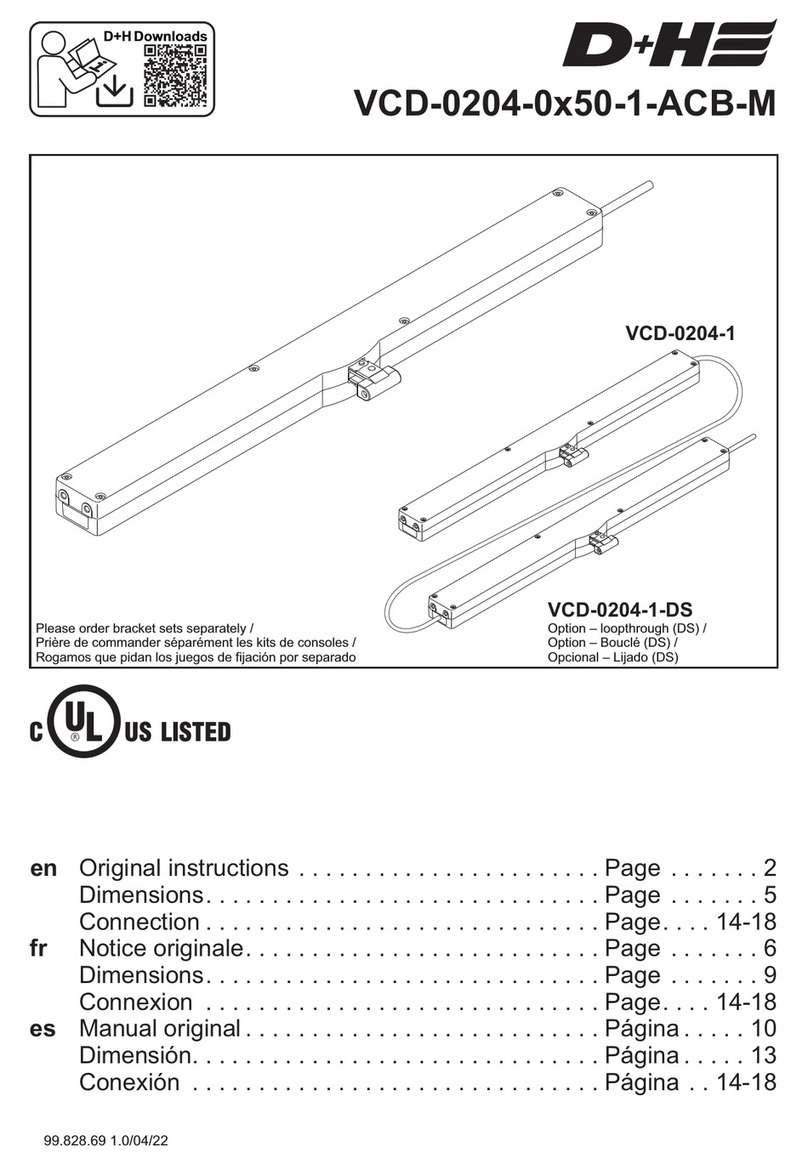
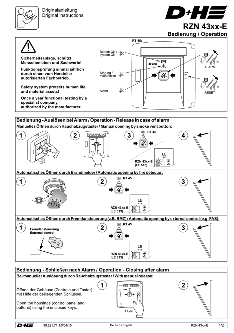
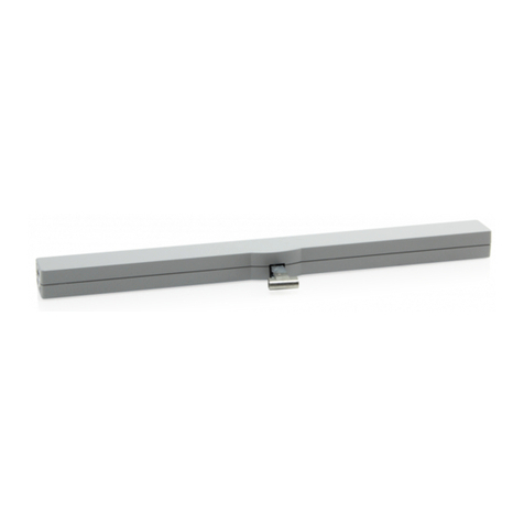
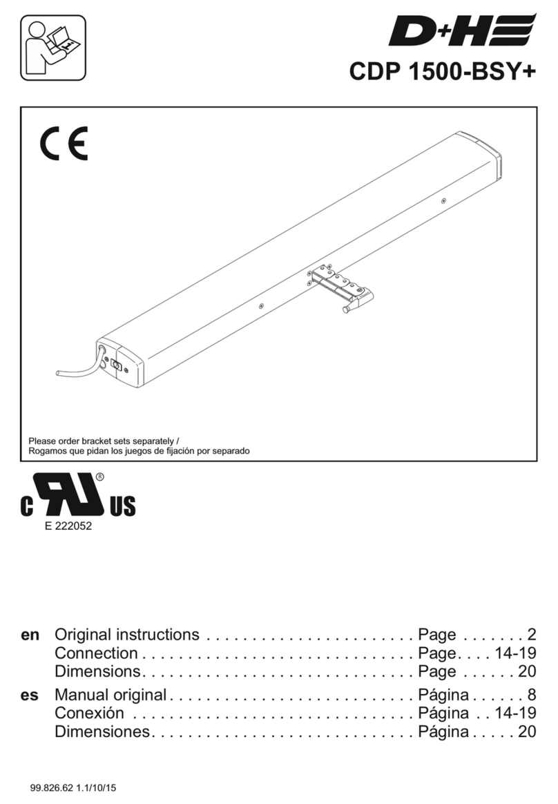
D+H KA 34-ACB User manual

KA 34-ACB / KA 54-ACB
99.828.64 1.3/05/20
Standard version
Mirrored version (Option "-L")
en Original instructions . . . . . . . . . . . . . . . . . . . . . . . Page . . . . . . . 2
Connection . . . . . . . . . . . . . . . . . . . . . . . . . . . . . . Page . . . . . . . 8
Please order bracket sets separately

Technical Data
2/12 KA 34-ACB / KA 54-ACB English English
Observe maximum pressure load of the chain!
Maximum pressure load of the chain is not
automatically identical with maximum pressure force
of the drive!
Pressure load diagram
KA 54-BSY+ KA 34-BSY+
100
200
300
400
500
600
700
800
500
400
300
200
100
0
max. Load (N)
Stroke / (mm)
Safety notes
Safety extra low voltage 24 V DC!
Do not connect directly to the mains supply!
- Connection has to be carried out only by an
authorized electrical specialist
- Danger of violent pressure in handaccessible area
- Keep away people from the operating area of the
drive
- Keep away children from the control
- Observe pressure load diagram of the chain!
- Use only in dry rooms
- Only for inside mounting.
Use rain detector with danger of rain
(e.g. at domelights or roof windows)
- This product may not be operated without the
covering stoppers, which are delivered with
bracket sets
- Just use unchanged original D+H parts
- Observe mounting instructions of bracket set!
Observe enclosed r ed safety slip!
Performance features
- ACB (Advanced Communication Bus) bus interface
with ModBus protocol for the connection to
compatible D+H control panels or direct integration
into building management systems, for example
- Microprocessor controlled synchro electronics
BSY + for a precise synchronous run of up to
8 drives
- Individually programmable (via software SCS)
- SHEV-high speed function (fast-running
feature in OPEN-direction)
- Protection system for the main closing edge
- Locking relief after closing
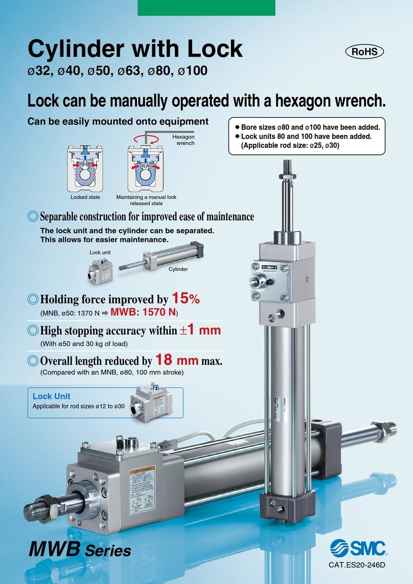
Drive unit with 2,5 m silicone cable. Dependent on
the type of window, different bracket sets are
available separately.
Extent of supply
Intended use
- Chain drive for electric opening and closing of
windows and flaps in the facade and roof area
- Operating voltage 24 V DC stabilized
- Useable for smoke ventilation as well as daily
natural ventilation
- Only for inside mounting
WARNING
Read all safety warnings, instructions, illustrations
and specifications provided with this product.
Failure to follow all instructions listed below may
result in electric shock, fire and/or serious injury.
Save all warnings and instructions for future
reference.
* Programmable with software SCS
Opening and Closing Ranges
Type
KA 34-ACB
Nominal current
1 A
Nominal stroke length*
600 mm, 800 mm
Nominal locking force
Service life
Duty cycle
Housing
Ingress protection
Temp. range
Fire stability
Ambient humidity
Emission sound pressure level
Additional functions*
approx. 2000 N
>20.000 double strokes
30 % (With cycle time 10 minutes)
Aluminium powdercoated (~ RAL 9006)
IP 32 th bracket sets)(With covering stoppers delivered wi
-5 ... +75 °C
30 min / 300 °C
≤ 90 %, not condensing
LpA 70 dB(A)≤
Closing edge protection = activated (3 repetitions of stroke);
Locking relief = activated (retraction lift max. 0,2 mm)
C3*
Nominal stroke -100 mm
300 N
7 mm/s
(16,1 mm/s)
O1*
C1* C2*
O2* O3*
23 mm
150 N
5 mm/s
(5 mm/s)
77 mm
150 N
5 mm/s
(5 mm/s)
23 mm
500 N
7 mm/s
(16,1 mm/s)
15 mm
500 N
7 mm/s
(16,1 mm/s)
Nominal stroke -38 mm
500 N
7 mm/s
(16,1 mm/s)
Range
Force
Speed
(SHEV high-speed)
KA 34-ACB / KA 54-ACB 3/12
99.828.64 1.3/05/2099.828.64 1.3/05/20
ACB bus interface
ACB is used for secure communication between the
drive and compatible D+H control systems. It
enables activation, diagnostics and configuration
with perfect position, directly from the control panel.
In this process, all status messages, such as the
OPEN and CLOSED signals, opening stroke and
drive errors, are transmitted to the control panel.
BSY+ synchronised electronics:
A synchronous group can contain up to 8 drives,
which communicate via bus. Each drive has its own
address, configurable with SCS.
The last drive of a synchronous group is the master,
which controls the other drives, the slaves.
Differences in forces between the drives of a group
are balanced by means of intelligent force and
position control. In the event that a drive
malfunctions, all the drives are automatically cut off.
Functional description

4/12
5/12
English English
Technical Data
* Programmable with software SCS
Opening and Closing Ranges
Type
KA 54-ACB HP800 / SB III
Nominal current
1,8 A
Nominal stroke length*
1200 mm
Nominal locking force
Service life
Duty cycle
Housing
Ingress protection
Temp. range
Fire stability
Ambient humidity
Emission sound pressure level
Additional functions*
approx. 2000 N
>10.000 double strokes
30 % (With cycle time 10 minutes)
Aluminium powdercoated (~ RAL 9006)
IP 32 (With covering stoppers delivered with bracket sets)
-5 ... +75 °C
30 min / 300 °C
≤ 90 %, not condensing
LpA 70 dB(A)≤
Closing edge protection = activated (3 repetitions of stroke);
Locking relief = activated (retraction lift max. 0,2 mm)
C3*
Nominal stroke -100 mm
800 N
7 mm/s
(17,2 mm/s)
O1*
C1* C2*
O2* O3*
23 mm
150 N
5 mm/s
(5 mm/s)
77 mm
150 N
5 mm/s
(5 mm/s)
23 mm
500 N
7 mm/s
(17,2 mm/s)
15 mm
500 N
7 mm/s
(17,2 mm/s)
Nominal stroke -38 mm
500 N
7 mm/s
(17,2 mm/s)
Range
Force
Speed
(SHEV high-speed)
Technical Data
* Programmable with software SCS
Opening and Closing Ranges
Type
KA 54-ACB
Nominal current
1,4 A
Nominal stroke length*
800 mm, 1100 mm, 1200 mm
Nominal locking force
Service life
Duty cycle
Housing
Ingress protection
Temp. range
Fire stability
Ambient humidity
Emission sound pressure level
Additional functions*
approx. 2000 N
>20.000 double strokes
30 % me 10 minutes)(With cycle ti
Aluminium powdercoated (~ RAL 9006)
IP 32 (With covering stoppers delivered with bracket sets)
-5 ... +75 °C
30 min / 300 °C
≤ 90 %, not condensing
LpA 70 dB(A)≤
Closing edge protection = activated (3 repetitions of stroke);
Locking relief = activated (retraction lift max. 0,2 mm)
C3*
Nominal stroke -100 mm
500 N
7 mm/s
(17,2 mm/s)
O1*
C1* C2*
O2* O3*
23 mm
150 N
5 mm/s
(5 mm/s)
77 mm
150 N
5 mm/s
(5 mm/s)
23 mm
500 N
7 mm/s
(17,2 mm/s)
15 mm
500 N
7 mm/s
(17,2 mm/s)
Nominal stroke -38 mm
500 N
7 mm/s
(17,2 mm/s)
Range
Force
Speed
(SHEV high-speed)
KA 34-ACB / KA 54-ACB KA 34-ACB / KA 54-ACB
99.828.64 1.3/05/2099.828.64 1.3/05/20

6/12 English
Shift of drive cable
The drive will be full configured by factory.
The drives must be reconfigured in case of
alterations (e.g. removing of drives
from existing set or integrating
a new drive) with SCS.
If after mounting the measure x is as bigger as
23 mm, null balance with software SCS is neccesary.
Closure Ranges will shift in relation to new zero
point.
Mount the drives mechanical stress-free.
With that, a better load distribution
is ensured on all the drives.
At vertical active pulling application (e.g. for a
skylight) the forces must be rearranged by software
SCS
Slave 1
Mounting informations
≥ 23 mm ?
X
Main closing edge
Beside closing edge
Beside
closing edge
Closing edge protection
In the "CLOSE" direction the drive has an active
protection for the main closing edge. If there is an
overload in the closing range 3 and 2, the drive runs
"OPEN" for 10 seconds, then "CLOSE" again. If after
three attempts closing is not possible, the drive
remains in this position.
In addition, the drive is equipped with passive
protection. The closing speed in closing range 2 and
1 is reduced to 5 mm/s.
Significantly greater forces can be
exerted at the secondary closing
edges. Danger of crushing hands and
fingers!
7/12
English
99.828.64 1.3/05/2099.828.64 1.3/05/20
Electrical devices, accessories, batteries and packa-
ging should be sorted for environmental-friendly
recycling. Do not dispose electrical devices and
batteries into household waste!
Only for EC countries:
According the European Guideline 2012/19/EU for
waste electrical and electronic equipment and its
implementation into national right, electrcal devices
that are no longer usable must be collected separa-
tely and disposed of in an environmentally correct
manner.
DisposalDeclaration of Conformity
We declare under our sole responsibility that the
product described under “Technical Data” is in
conformity with the following directives:
2014/30/EU, 2014/35/EU
Technical file at:
D+H Mechatronic AG, D-22949 Ammersbek
Dirk Dingfelder Maik Schmees
Member of the Board Authorized signatory, Technical Director
18.05.2020
Maintenance and cleaning
Maintenance work is only allowed when the device is in
a de-energized condition! Inspection and maintenance
has to be carried out according to D+H maintenance
notes. Only original D+H spare parts may be used.
Repair is to be carried out exclusively by D+H.
Wipe away debris or contamination with a dry, soft
cloth.
Do not use cleaning agents or solvents.
Guarantee
You will get 2 years guarantee for all D+H products
from date of verified handing over of the system up to
maximal 3 years after date of delivery, when
mounting and starting has been carried out by an
authorized D+H-distributor.
D+H guarantee is expired, with connection of D+H
components with external systems or with mixing of
D+H products with parts of other manufacturers.
Visual inspection:
Only one master drive is allowed.
The master always has the last address of all the
drives; this can be found on a sticker attached to
the drive. Slaves are numbered downwards from
the master, so that in a group of three drives, for
example, the master is no. 3, with a slave 2 and
slave 1 drive. Please note that this only applies in
the ex-factory configuration. As soon as the drives
are reconfigured with SCS, the ex-factory
addressing no longer applies.
Wiring:
Is the drive or drive group wired properly?
See connection plans.
Diagnostics with SCS software:
The SCS software and a BSY+ interface is
required for further troubleshooting or
configuration.
Troubleshooting
KA 34-ACB / KA 54-ACB KA 34-ACB / KA 54-ACB

8/12 English 9/12
English
(4)
Abzweigdose / Junction box /
Boîte de dérivation / Caja de conexión
BSY+
Master BSY+
Slave (s)
(1)
110 Ω
2 or 3 drives star-shaped
Group
Mot.a
ACB.a
Mot.b
ACB.b
CPS-M (AM)
(1)/(2)
110 Ω
(GN)
BSY+.b
(YE)
BSY+.a
(GY)
ACB.b
(OG)
ACB.a
(BN)Mot. b
(WH)Mot. a
KA-ACB
(GN)
BSY+.b
(YE)
BSY+.a
(GY)
ACB.b
(OG)
ACB.a
(BN)Mot. b
(WH)Mot. a
KA-ACB
(GN)
BSY+.b
(YE)
BSY+.a
ACB.b
ACB.a
(BN)Mot. b
(WH)Mot. a
KA-ACB
(GN)
BSY+.b
(YE)
BSY+.a
(GY)
ACB.b
(OG)
ACB.a
(BN)Mot. b
(WH)Mot. a
KA-ACB
BSY+
Slave 1
(4)
Abzweigdose / Junction box /
Boîte de dérivation / Caja de conexión
BSY+
Master 2
(1)
110 Ω
(3)
Group
Mot.a
ACB.a
Mot.b
ACB.b
CPS-M (AM)
(1)/(2)
110 Ω
Connection
Pin Assignment
Connection
BN (Mot. b)
OG (ACB.a)
GY (ACB.b)
GN (BSY+.b)
YE (BSY+.a)
WH (Mot. a)
Notes
(1) Termination:
The ACB segment must be terminated with 2 resistors (110 Ω).
The resistors must in each case be connected at the end of the cable.
(2) Integrated resistor
(3) Protect wire against short circuit
(4) Cable according to D+H table for layout of cables (See instructions for use of control panel)
(WH) weiss / white / blanc / blanco
(BN) braun / brown / brun / marrón
(OG) orange / orange / orange / naranja
(YE) gelb / yellow / jaune / amarillo
(GN) grün / green / vert / verde
(PK) rosa / pink / rose / rosa
(GY) grau / grey / gris / gris
2 up to max. 3 drives looped through
KA 34-ACB / KA 54-ACB KA 34-ACB / KA 54-ACB
99.828.64 1.3/05/2099.828.64 1.3/05/20

10/12 English 11/12
English
KA 34-ACB / KA 54-ACB KA 34-ACB / KA 54-ACB
99.828.64 1.3/05/2099.828.64 1.3/05/20
Connection
Master
Master
Slave
5 cm 1,5 cm
Master Slave
2 3
4
1
8
350
500
600
700
800
1000
1100
1200
1300
247,5
322,5
372,5
422,5
472,5
576,5
628,5
678,5
728,5
A B
421
496
546
596
646
750
802
852
902
H
Dimensions
B
173,5 mm A
40 mm
51 mm
H

D+H Mechatronic AG
Georg-Sasse-Str. 28-32
22949 Ammersbek, Germany
Tel.: +4940-605 65 239
Fax: +4940-605 65 254
E-Mail: [email protected]
www.dh-partner.com
© 2020 D+H Mechatronic AG, Ammersbek
Rights to technical modifications reserved
100 % Recycled paper 99.828.64 1.3/05/20
This manual suits for next models
2
Table of contents
Other D+H Industrial Equipment manuals
Popular Industrial Equipment manuals by other brands
Zimmer
Zimmer PowerStop PHE16X10LSAK-A Installation and operating instructions
Opex
Opex Falcon+ Operator's manual
Hardinge
Hardinge FlexC Low Profile Dead-Length Collet System Style... Installation instructions and parts list
Axminster Trade
Axminster Trade AT50LP Ultimate Edge Original instructions
Innova
Innova XTIRPA IN-8020 Instruction and safety manual
Kval
Kval ON-3V Service manual
