TBB NEMO Series User manual


NEMO series battery to battery Charger

NEMO series battery to battery Charger
CAUTION: THE NEMO MUST BE ISOLATED BEFORE SERVICING
MADE IN CHINA

NEMO series battery to battery Charger
Disclaimer
Unless specially agreed in writing, TBB Power Co.,Ltd.
▪Take no liability as to the accuracy, sufficiency or suitability of any technical or other
information provided in this manual or other documentation.
▪Assumes no responsibility or liability for loss or damage, whether direct, indirect,
consequential or incidental, which might arise out of the use of such information.
▪TBB offers standard warranty with its products, taking no responsibility for direct or indirect
loss due to equipment failure.
About this Manual
This manual describes our product features and provides instructions for installations. This
manual is for anyone intending to install our equipment.
General Instruction
Thanks for choosing our products and this manual is suitable for the Nemo range of battery
to battery chargers also known as DC-DC chargers.
This chapter contains important safety and operation instructions. Read and keep this User
Guide safe for later reference.

NEMO series battery to battery Charger
Contents
1. General Safety Instruction ............................................................................................... 1
1.1 Safety Instruction .................................................................................................... 1
1.2 General Precaution ................................................................................................. 1
1.3 Precaution regarding battery operation ................................................................... 1
2. Description of main functions ........................................................................................... 2
2.1 General Description ................................................................................................ 2
2.2 Principle Diagram ................................................................................................... 3
2.3 Model Information ................................................................................................... 3
3. Structure .......................................................................................................................... 5
3.1 Terminal and panel definition .................................................................................. 5
3.2 Structure dimension ................................................................................................ 7
4. Preparation and Configuration ......................................................................................... 8
4.1 Material list ............................................................................................................. 8
4.2 Location .................................................................................................................. 8
4.3 Battery type setting ................................................................................................. 8
4.4 Wiring and Fuse recommendation .......................................................................... 9
5. Installation and Connection ............................................................................................ 10
5.1 General advice...................................................................................................... 10
5.2 Connecting the power cable ................................................................................. 10
6. Operation ....................................................................................................................... 14
6.1 Double check ........................................................................................................ 14
6.2 LED Description .................................................................................................... 14
6.2.1 For DX and IDX series ................................................................................ 14
6.2.2 For DDX and IDDX series ........................................................................... 14
6.3 LEDs indicate the normal working status .............................................................. 16
7. FAQ ................................................................................................................................ 17
8. Specification .................................................................................................................. 18

NEMO series battery to battery Charger
1
1. General Safety Instruction
1.1 Safety Instruction
As dangerous voltages and high temperatures exist within the charger, only qualified and
authorized maintenance personnel are permitted to open and repair it. Please make sure
the charger is turned off before attempting to dismantle or open it.
This manual contains information concerning the installation and operation of the charger.
All relevant parts of the manual should be read prior to commencing the installation. Please
follow the local regulations regarding electrical installations.
Any operation against safety requirement or against intended use, manufacture, safety
standard, will be out of the manufacturer warranty.
1.2 General Precaution
To avoid fire and electric shock and poor performance, make sure all cables that are selected
meet the wiring recommendations as per table 4-3 and table 4-4. Ensure a good electrical
connection. Smaller diameter and broken or poor-quality cable should not be used. It is
always recommended to suitably fuse the input and output of the Nemo.
Never place unit directly above batteries, gases from a battery will corrode and damage
charger.
Do not place battery over charger.
1.3 Precaution regarding battery operation
Use plenty of fresh water to clean in case battery acid contacts skin, clothing, or eyes and
consult with doctor as soon as possible.
The battery may generate flammable gas during charging. NEVER smoke or allow a spark
or flame in vicinity of a battery.
Do not put any metal tool or object on the battery, spark and short circuit might lead to
explosion.
REMOVE all personal metal items such as rings, bracelets, necklaces, and watches while
working with batteries. Batteries can cause short-circuit current high enough to make metal
melt and could cause severe burns.

NEMO series battery to battery Charger
2
2. Description of main functions
2.1 General Description
Nemo battery to battery charger is a simple but perfect in vehicle charging solution. It draws
power from alternator to perform quick and reliable charging of auxiliary batteries while you
are driving or stationary via solar. Compatible with Euro6 vehicles, Nemo maintains charge
with a stable output even with variable voltage “smart alternators”, to ensure your battery
receives a full charge in the shortest time without concerns about overcharging or
undercharging which can reduce life cycle of your batteries.
DC-DC charging solution protects your auxiliary battery by regulating voltage and
controlling output current.
TBB premium II multistage charging algorithm for various battery chemicals including
LFP.
Built in automatic temperature and voltage compensated battery charging.
Support auxiliary battery (AGM, GEL and WET) low voltage (under 2V) detect before
the charger charging and LFP wake-up with continuous output.
Compatible with Euro 6 engine(variable voltage smart alternators).
Battery protection function prevents deep-discharge of starter battery.
Dual input model with built in solar charge controller (MPPT) is available for DDX\IDDX.
Model with 12Vdc input and 24Vdc output is available.
Compact and waterproof IP63 rated without fan for convenient installation.
Multiple units can be connected in parallel to increase output current.
Provides maintenance solar charge to starter battery when auxiliary battery is full.
Suitable for supporting loads up to maximum output rating while on the move.
E-Mark approval.
2-year warranty.

NEMO series battery to battery Charger
3
2.2 Principle Diagram
Alternator
starter battery
PV panel
IGN
Temperature
and voltage
compensated
DC/DC
MCU
Auxiliary
battery
LED
RS485
Figure 2-1 Functional block diagram of the charger
2.3 Model Information
Example: I D DX 12 30 x
Communication function
MPPT
Device family
Output rated voltage
Output rated current
Vehicle output voltage(ALT)
I:enable
D:with MPPT
Default:without MPPT
Default:disable
DX:DCDC converter
12:output rated voltage is 12V.
24:output rated voltage is 24V.
15:output rated current is 15A.
30:output rated current is 30A.
L:vehicle output voltage is 12V.
Default:same with output.
Figure 2-2 Ordering information scheme
Table 2-1 Model series
Model Alternator PV RS485

NEMO series battery to battery Charger
4
charger charger
DX1215, DX1230,DX2415, DX2415L ○
DDX1230, DDX2415, DDX2415L ○ ○
IDX1215, IDX1230,IDX2415, IDX2415L ○ ○
IDDX1230, IDDX2415, IDDX2415L ○ ○ ○
NEMO series battery to battery Charger
5
3. Structure
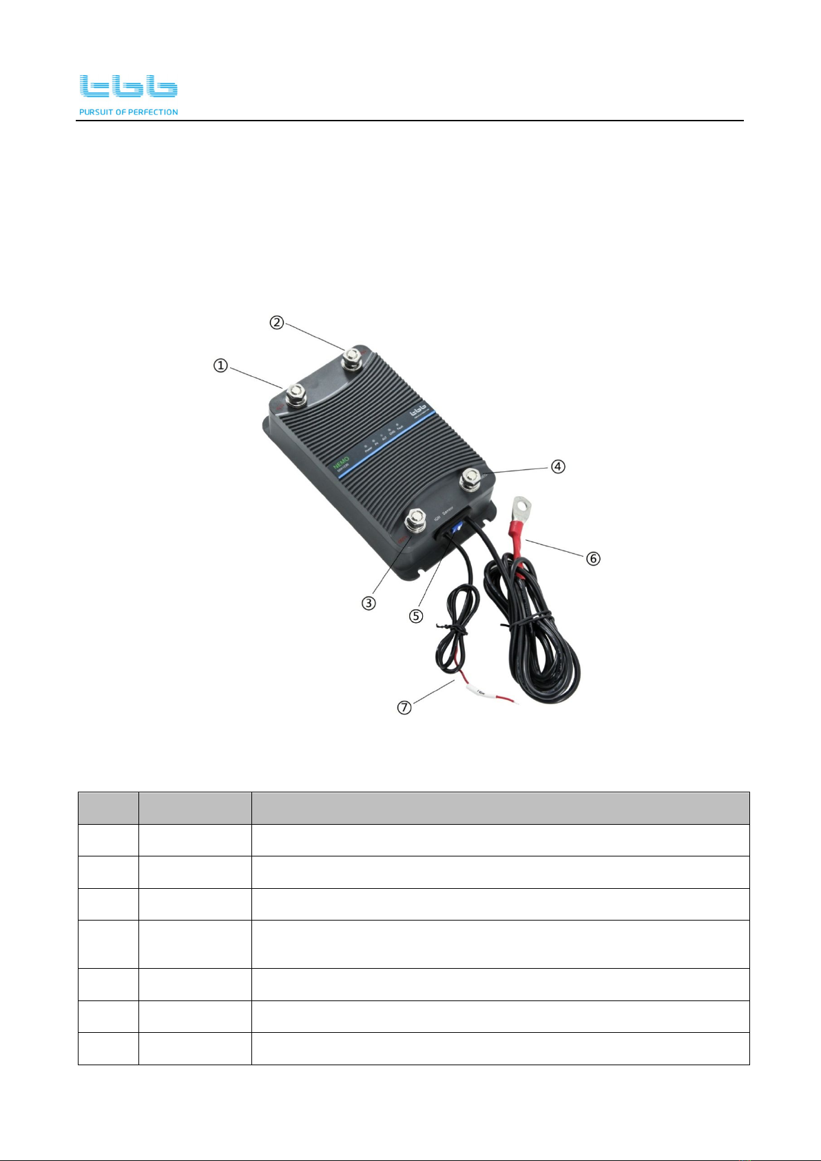
3.1 Terminal and panel definition
There are two different cable configurations available as per figure 3-1 and figure 3-2 for
DX and DDX models. They have no difference in function.IDX / IDDX models are for OEM
and have more adjustable settings via PC software (ask your dealer for more information
and refer to Figure 5-3 on page 12). The panel and terminal definition are as follow.
Figure 3-1 Charger model and cable for DX/DDX model
Table 3-1 Connectors or Terminals Description
NO. Definition Description
1 ALT+ Alternator IN + , Starter Battery +
2 PV+ PV IN+ (only available for DDX and IDDX)
3 OUT+ Aux battery+
4 NEG- Common Negative for PV-, Alternator/Starter battery-, Aux
battery-
5 Dip switch Battery type setting
6 Sensor Temperature and voltage sensor
7 IGN Ignition feedback wire

NEMO series battery to battery Charger
6
Figure 3-2 Charger model and extension cable
Table 3-2 Connectors or Terminals Description
NO. Definition Description
1 ALT+ Alternator IN +, Starter Battery +
2 PV+ PV IN+ (only available for DDX and IDDX)
3 OUT+ Aux battery+
4 NEG- Common Negative for PV-, Alternator/Starter battery-, Aux
battery-
5 Dip switch Battery type setting
6 IGN Ignition feedback wire
7 Sensor Temperature and voltage sensor
8 COM Communication – RS485(only for IDX and IDDX)
9 Extension
cable Temperature/Voltage, Ignition sensor and RS485 cable

NEMO series battery to battery Charger
7
3.2 Structure dimension
Figure 3-3 Structure dimension of the charger

NEMO series battery to battery Charger
8
4. Preparation and Configuration
4.1 Material list
The unit is supplied with the following materials. Please confirm the serial number on charger
is same to that on outer carton.
NEMO battery to battery charger.
User manual.
Sensor / Ignition / RS485 (model dependent for IDX and IDDX).
4.2 Location
Please install the equipment in a clean, cool location with good ventilation.
Working temperature: -20℃~+60℃.
Storage temperature: -40℃~+85℃.
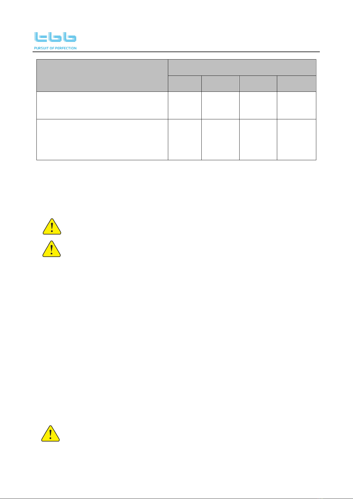
4.3 Battery type setting
Table 4-1 Switch status for battery type and charging voltage
Switch status Battery type
Charging Voltage (V)
Absorption Floating
12V 24V 12V 24V
OFF, OFF AGM 14.6 29.2 13.5 27
OFF, ON GEL 14.2 28.4 13.8 27.6
ON, OFF LFP 14.4 28.8 13.5 27
ON, ON WET 14.8 29.6 13.8 27.6

NEMO series battery to battery Charger
9
4.4 Wiring and Fuse recommendation
Please find the following recommended cable size and fuse rating.
We recommend that a fuse is installed on the input and output of the Nemo closest to the
battery.
Fuse recommendation
Table 4-2 Fuse recommendation
Model
Input Output
Max
current
fuse
Max
current
fuse
DX1230, DDX1230, IDX1230,IDDX1230 40A 50A 30A 40A
DX1215, IDX1215, DX2415, DDX2415,
IDX2415, IDDX2415 20A 25A 15A 20A
DX2415L, DDX2415L, IDX2415L, IDDX2415L 40A 50A 15A 20A
Wiring recommendation
Table 4-3 Input wiring recommendation
Model
Recommended wiring
1m 2m 5m 10m
DX1230,DDX1230,IDX1230,IDDX1230
DX2415L,DDX2415L,IDX2415L,
IDDX2415L
6mm2
or
AWG9
10mm2or
AWG7
16mm2
or
AWG5
25mm2 or
AWG3
DX1215, IDX1215, DX2415, DDX2415,
IDX2415, IDDX2415
4mm2
or
AWG11
6mm2 or
AWG9
10mm2
or
AWG7
16mm2 or
AWG5
Table 4-4 Output wiring recommendation
NEMO series battery to battery Charger
10
Model
Recommended wiring
1m 2m 5m 10m
DX1230, DDX1230,IDX1230,
IDDX1230
6mm2
or
AWG9
10mm2
or
AWG7
16mm2
or
AWG5
25mm2 or
AWG3
DX1215, IDX1215, DX2415, DDX2415,
IDX2415, IDDX2415, DX2415L,
DDX2415L, IDX2415L, IDDX2415L
4mm2
or
AWG11
6mm2 or
AWG9
10mm2
or
AWG7
16mm2 or
AWG5
5. Installation and Connection
For the user’s operation safety, cut off the power before installation.
Please double check the battery voltage matching the model installed.
5.1 General advice
Select a suitable place to install the battery to battery charger, ensuring adequate ventilation
to the charger’s metal body, free from excessive heat and vibration. The electronics are
enclosed in a sealed housing. However, the charger is NOT designed to be installed in a
location where water might short between terminals.
All cables installed must be fused. The fuse should be installed as close as possible to
the power source (battery).
Connections from the battery must be fused closed to the battery.
Use M5 screws to secure the charger in a solid surface.
5.2 Connecting the power cable
Please ensure the correct polarity when connecting. Reverse polarity will
burn the fuse or damage the charger and void warranty.
NEMO series battery to battery Charger
11
When installing this unit on Euro6 vehicle with variable voltage “smart
alternator”, please connect IGN wire.
For safety, please always connect ground (NEG.-) first and then connect the Aux battery
positive, starter battery positive and PV positive respectively.
1) Connect battery negative. Connect the negative power cable to the battery to battery
charger and connect the other end of negative cable to main battery negative terminal
or directly to the chassis, ensuring a good solid electrical connection.
2) Connect the auxiliary battery. Connect the positive power cable between terminals
marked OUT+ on battery to battery charger and the auxiliary battery positive terminal.
Ensure the in-line fuse is removed prior to connecting the cable and inserted afterwards.
3) Connect the starter battery. Connect the positive power cable between terminals marked
ALT+ on battery to battery charger and the starter battery positive terminal. Ensure the
in-line fuse is removed prior to connecting the cable and inserted afterwards.
4) Connect the PV. Connect the positive power cable between terminals marked PV+ on
battery to battery charger and the PV positive cable. Ensure the in-line fuse is removed
prior to connecting the cable and inserted afterwards.
5) Connect the ignition wire.
6) Connect the battery sensor.
7) Connect the RS485 communication cable (model dependent RS484 also used for
programming IDX/IDDX).
The MAX VOC PV input is 25VDC for 12V models and 50VDC for 24V
models(open circuit voltage).
Please double check the solar panel you are going to install matching the
maximum voltage of PV input.

NEMO series battery to battery Charger
12
Figure 5-1 Connecting diagram of the model in real installation
The built-in battery sensor includes the voltage and temperature detection of the auxiliary
battery. The detection is used to compensate the charging voltage. It must be connected at
the positive of the auxiliary battery.
Auxiliary Battery
Sensor
+-
Figure 5-2 Connecting diagram of the sensor cable

NEMO series battery to battery Charger
13
For IDX and IDDX models, RS485 cable can be connected to a PC monitor or a controller
to view some working information of the charger. The RS485 protocol can be obtained
from our sales team if needed, please contact your local distributor.
Monitor
RS485 A+
(Red)
RS485 B-
(Black)
RS485
Figure 5-3 Connecting diagram of the RS485 cable

NEMO series battery to battery Charger
14
6. Operation
6.1 Double check
Before operation, please ensure the following steps are ensured.
The battery voltage matches the charger model.
Polarity of cable connection is correct.
Voltage sensor is installed on the positive terminal of battery.
Ignition wire is connected for Euro 6 vehicles.
6.2 LED Description
6.2.1 For DX and IDX series
Figure6-1 Front panel of LED indication for DX and IDX series
6.2.2 For DDX and IDDX series
Figure 6-2 Front panel of LED indication for DDX and IDDX series

NEMO series battery to battery Charger
15
Table 6-1 Description of the LEDs status
LED name Color Status Description
Power green Solid ON Input normal
ALT green
Solid ON Alternator is charging the battery.
Slow Flashing Alternator input is good and
synchronized with PV charging.
Quick Flashing Alternator input is overvoltage.
CHG green
Flashing Nemo is charging the battery.
Solid ON Battery is charged.
OFF No charging
Fault red
Flashing Battery over-temp, charger over-temp
Solid ON Output overvoltage, battery internal
failure
PV green
Solid ON PV is charging the battery
Slow Flashing P
V input is good and synchronized with
alternator charging.
Quick Flashing PV input overvoltage
This manual suits for next models
14
Table of contents
Other TBB Batteries Charger manuals


Popular Batteries Charger manuals by other brands


Enerwatt
Enerwatt EWC612-1 user manual

Schumacher Electric
Schumacher Electric SL3 Series owner's manual

VOLTCRAFT
VOLTCRAFT UFC-1S operating instructions

WEG
WEG WEMOB-STATION-CCS-30kW Series Installation and operation manual

Power Saver
Power Saver BC-012-20A Service manual

hager
hager XEV6 Series quick start guide