TBB Bi1248-1200 User manual
Bi1248‐1200UserManual
TBBPowerCo.,Ltd
Bi-directional Converter Charger
Bi1248-1200
User Manual
Version:A1.0
Date:Dec.2019

Bi1248‐1200UserManual
TBBPowerCo.,Ltd
WARNING:FIREHAZARD
SUITABLEFORMOUNTINGONCONCRETEOROTHER
NON‐COMBUSTABLESURFACEONLY
CAUTION:THEDCANDACBREAKERMUSTHAVEBEEN
TURNEDOFFBEFORESERVICING
MADEINCHINA

Bi1248‐1200UserManual
TBB Power Co.,Ltd
D
Di
is
sc
cl
la
ai
im
me
er
r
Unlessspeciallyagreedinwriting,TBBPowerCo.,Ltd.
Takenowarrantyastotheaccuracy,sufficiencyofsuitabilityofanytechnicalorother
informationprovidedinthismanualorotherdocumentation.
Assumesnoresponsibilityorliabilityforlossordamage,whetherdirect,indirect,
consequentialorincidental,whichmightariseoutoftheuseofsuchinformation
TBBofferstandardwarrantywithitsproducts,takingnoresponsibilityfordirectorindirect
lossduetoequipmentfailure.
A
Ab
bo
ou
ut
t
t
th
hi
is
s
M
Ma
an
nu
ua
al
l
Thismanualdescribesourproductfeaturesandprovidesprocedureofinstallations.Thismanual
isforanyoneintendingtoinstallourequipment.
G
Ge
en
ne
er
ra
al
l
I
In
ns
st
tr
ru
uc
ct
ti
io
on
n
ThanksforchoosingourproductsandthismanualweresuitableforDC/DCBi‐directional
ConverterBi1248‐1200.
Thischaptercontainsimportantsafetyandoperationinstructions.ReadandkeepthisUserGuide
wellforlaterreference.
TheDC/DCBi‐directionalConverterBi1248‐1200needstobeinstalledbyprofessionalsandplease
payattentiontothefollowingpointspriortoinstallation:
1>Pleasechecktheinputvoltageorvoltageofbatteryissametothenominalinputvoltageofthis
unit.
2>Pleaseconnectpositiveterminal“+”ofbatteryto“+”inputofthisunit.
3>Pleaseconnectnegativeterminal“‐”ofbatteryto“‐”inputofthisunit.
4>Pleaseusetheshortestcabletoconnectandensurethesecureconnection.
5>Whileconnecting,pleasesecuretheconnectionandavoidshortcutbetweenpositiveterminal
andnegativeterminalofbattery,whichwillcausedamageofbattery.
6>Thisunitwillhavehighvoltageinside.Onlyauthorizedelectriciancanopenthecase.
7>ThisunitWASNOTdesignedtouseinanyliferetainingequipment.

Bi1248‐1200UserManual
I
In
nd
de
ex
x
1.GeneralSafetyInstruction..........................................................................................................................1
1.1SafetyInstruction...............................................................................................................................1
1.2GeneralPrecaution............................................................................................................................1
1.3Precautionregardingbatteryoperation.........................................................................................1
2.DescriptionofmainFunction....................................................................................................................2
2.1Productintroduction.....................................................................................错误!未定义书签。2
2.2Productprinciple...............................................................................................................................2
2.3Features...............................................................................................................................................3
2.4Namingrule........................................................................................................................................4
3.Structure........................................................................................................................................................4
3.1Productdrawinganddimensiondrawing.....................................................................................4
4.Pre‐installationConfiguration...................................................................................................................5
4.1Unpackinginspection........................................................................................................................6
4.2Installationrequirements..................................................................................................................5
4.3Cablepreparation..............................................................................................................................5
5.Installation....................................................................................................................................................5
5.1Installationrecommendationsandoperations..............................................................................6
5.1.1Installationdrawing................................................................................................................7
5.2Wiringrecommendation...................................................................................................................8
5.2.1Wiringdiagram........................................................................................................................9
5.3COMterminaldefinition................................................................................................................10
6.UsersInstructions......................................................................................................................................11
6.1Poweroncheckandinstructions...................................................................................................11
6.2Indicatordefinition..........................................................................................................................12
6.3DIPswitchdefinition.........................................................................................................................8
6.4Moduleworkingconditions...........................................................................................................12
6.5Servicebatterychargingcurve.......................................................................................................13
6.6Operatingtemperaturederatingcurve.........................................................................................14
7.TechnicalDataSheet..................................................................................................................................15

Bi1248‐1200UserManual
1
1. GeneralSafetyInstruction
1.1SafetyInstruction
AsdangerousvoltagesandhightemperatureexistwithinBi1248‐1200,onlyqualifiedand
authorizedmaintenancepersonnelarepermittedtoopenandrepairit.Pleasemakesure
Bi1248‐1200isturnedoffbeforeopenandrepairit.
ThismanualcontainsinformationconcerningtheinstallationandoperationofBi1248‐1200.All
relevantpartsofthemanualshouldbereadpriortocommencingtheinstallation.Pleasefollowthe
localstipulationmeantime.
Anyoperationagainstsafetyrequirementoragainstdesign,manufacture,safetystandard,andare
outofthemanufacturerwarranty.
1.2GeneralPrecaution
Donotexposetodust,rain,snoworliquidsofanytype,itisdesignedforindooruse.DONOT
blockoffventilation,otherwiseBi1248‐1200wouldbeoverheating.
Toavoidfireandelectricshock,makesureallcablesselectedwithrightgaugeandbeing
connectedwell.Smallerdiameterandbrokencablearenotallowedtouse.
PleasedonotputanyinflammablegoodsneartoBi1248‐1200.
NeverplaceBi1248‐1200directlyabovebatteries,gasesfromabatterywillcorrodeanddamageit.
DonotplacebatteryoverBi1248‐1200.
1.3Precautionregardingbatteryoperation
Useplentyoffreshwatertocleanincasebatteryacidcontactsskin,clothing,oreyesandconsult
withdoctorassoonaspossible.
Thebatterymaygenerateflammablegasduringcharging.NEVERsmokeorallowasparkorflame
invicinityofabattery.
Donotputthemetaltoolonthebattery;sparkandshortcircuitmightleadtoexplosion.
REMOVEallpersonalmetalitemssuchasrings,bracelets,necklaces,andwatcheswhileworking
withbatteries.Batteriescancauseshort‐circuitcurrenthighenoughtomakemetalmelt,andcould
causesevereburns.
Bi1248‐1200UserManual
2
2. DescriptionofmainFunction
2.1GeneralDescription
Bi1248‐1200isabi‐directionalconverterchargerforvehiclesorboatwhichhasdualbatterysystem
installed.Itwasdesignedtocharge48Vdcauxiliarybatteryona12Vdcchassis.Duetoits
bi‐directionaldesign,the12Vdcloadcanbepoweredasitusedtobe.
Upondrivingorengineon,throughthisdevice,theoutputof12Vdcalternatorcanbeusedto
charge48Vdcauxiliarybatteryandmeantimepowerthe12Vdcloads.Uponenginestop,this
devicewillconvert48Vdcinto12Vdc,poweringall12Vdcloads.
Traditionalalternator:Whenthedevicedetectsthatthestarterbatteryvoltageishigher
than13.3V,itwilltakespowerfromalternatortochargesthe48Vauxiliarybatterywitha
maximumchargingcurrentof25A.Uponthestarterbatteryvoltageislowerthan12.8V,
thisdevicewillstopworking.
Smartalternator/Euro6:Throughdipswitch,thisdevicecanbesettosmartalternator
mode.Afterchoosingthismode,IGNsignalorsimilarsignalwiremustbeconnected.
CombinedwithIGNsignalandvoltage,thedevicewilldecidethecharging.
Charging:IGNactiveandstarterbatteryvoltageishigherthan12.2V
Stopcharging:IGNactiveandthestarterbatteryvoltageislowerthan11.6V.
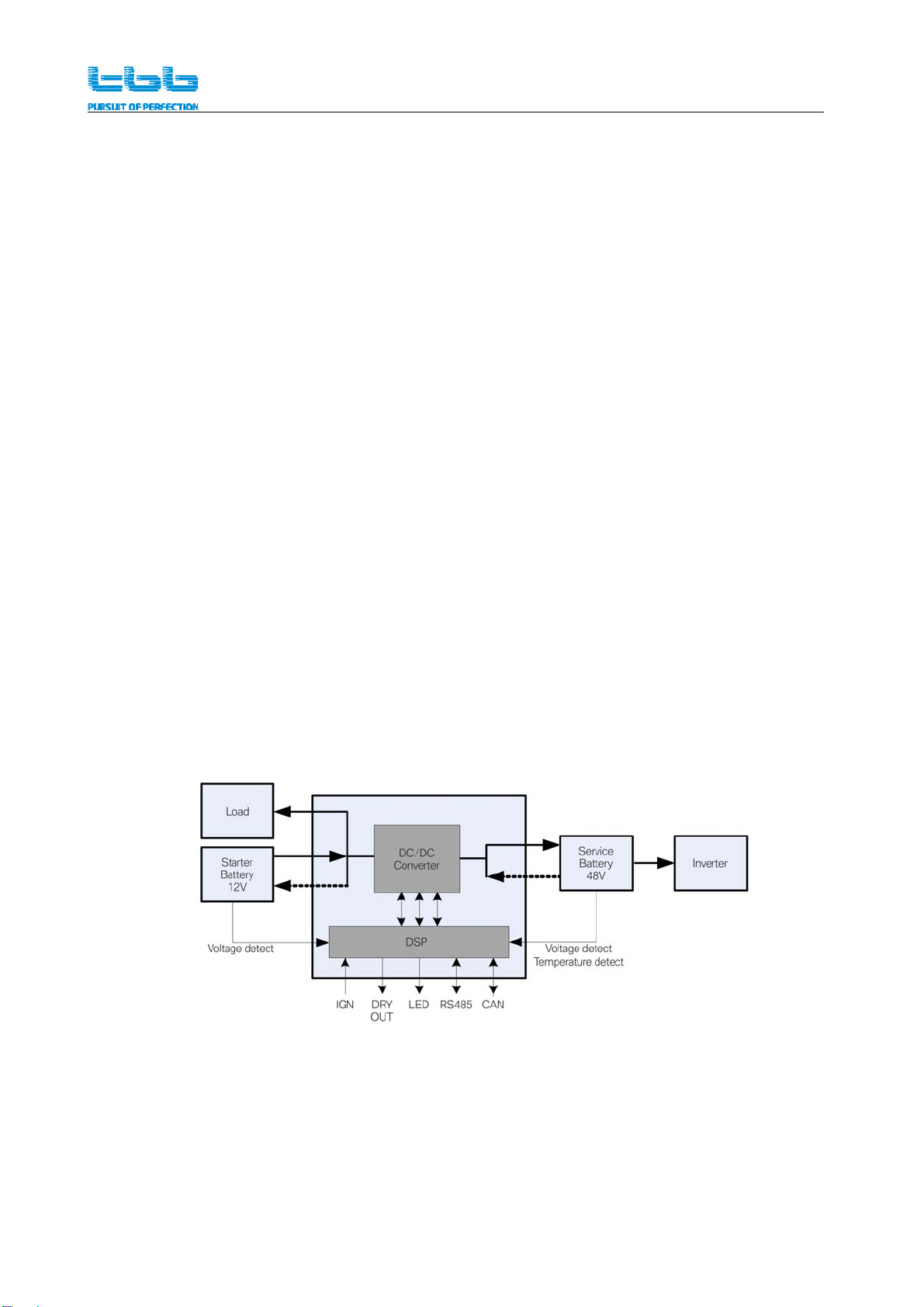
2.2Productprinciple
TheBi1248‐1200adoptsanon‐isolatedconversiontopologywithhighefficiencyupto94%or
above.AdoptingDSPcontrol,complexcontrolalgorithmscanbeachievedandmeantimefeaturing
highcontrolprecisionandfastresponsespeed.
Afterthestarterbatteryandtheservicebatteryareconnectedtotheunit,aswellastheIGNsignal,
theunitcanindependentlyimplementthechargeanddischargeandmaintainthereliable
operation.WithbuiltinisolatedRS485andCANcommunication,itcanbeusedforanysystem
withmonitoringandcontrolrequirement.

Bi1248‐1200UserManual
3
2.3Features
HighPowerin‐vehiclecharging,max1.2KWHcanbechargedperhour.
DSPcontrolwithfastandsophisticatedalgorithm
Non‐isolationdesignwithmaxefficiency94%
AlternatorInputrange11.6‐16Vdc,standingupto35Vdc
CanbeusedforEuro6withsmartalternator
Multiplebatterychemicalcanbechoseincludinglithiumbattery
TBBpremiumIImultiplestageschargingalgorithm
Builtinautomatictemperatureandvoltagecompensatedcharging
Thermalcontrolledfancooling
WithbuiltinRS485andCANcapability
Drycontactoutput,capacityof250Vac/28Vdc5A
Drycontactinput,forexternalcontroltopoweroffthedevice
Completeprotectionagainstoutputshortcircuit,outputovercurrent,over/lowvoltage,over
temperatureandoutputreversepolarity

Bi1248‐1200UserManual
4
3. Structure
3.1Dimension
306.3282.8
170
291.6
85
200
4-?5
301.6
Dimension:306.3*200*85mm
Weight:3kgs

Bi1248‐1200UserManual
5
4. Preparation
4.1Inspection
Afterunpacking,pleasecheckiftheunitisdamagedduringthetransportationandthereis
completesetofaccessories.
Usersmanual
Signalwire
4.2Installationrequirements
Storagetemperature‐40~+70°C
Workingtemperature‐25~+60°C,
Relativehumidity:5%‐95%,nocondensation
Coolingmethod:aircooling
Altitude:2000morless,meetingthederatingrequirementsofGB3859.2‐93
4.3CableandFusepreparation
Pleaserefertothetablebelowforcableandfusespecifications:
ModelConnectorNominal
CurrentRecommendedcableRecommende
dFuse
Bi1248‐120
0
12V+12Vdc100A length<2m,25mm²or3AWGand
above
Noextrafuse
requested
12V+andBAT‐ 12Vdc200A length<3m,35mm²or2AWGand
above250A
48V+andBAT‐ 48Vdc
25A
10mm²or7AWGandaboveNoextrafuse
requested
COM‐ 22AWG
Pleaseinstallacablefuseon12Vdcinputassafety.

Bi1248‐1200UserManual
6
5. Installation
Fortheuseroperationsafety,cutoffthepowerbeforeinstallation.
Pleasedoublecheckthattheinstalledbatteryvoltageis48Vdc
5.1Installationrecommendationsandoperations
ItisnecessarytoturnoffthepowerswitchorexternalcontrolsignaltopreventBi1248‐1200
fromworkingdueto,whichmaycausesparklingduringthewiringprocess.
PleaseselecttheappropriatelocationwithadequateventilationtoinstallBi1248‐1200,andfix
itwithM5screws.
Inordertoensuretheventilation,pleaseassureminimum10cmwithoutobstructionatboth
ends.And,minimum5cmatleftandrightside.
后
前
右
左
170
291.6
4-?5
≥5cm ≥5cm
≥10cm
≥10cm
Back
Left Right
Front
Bi1248‐1200UserManual
7
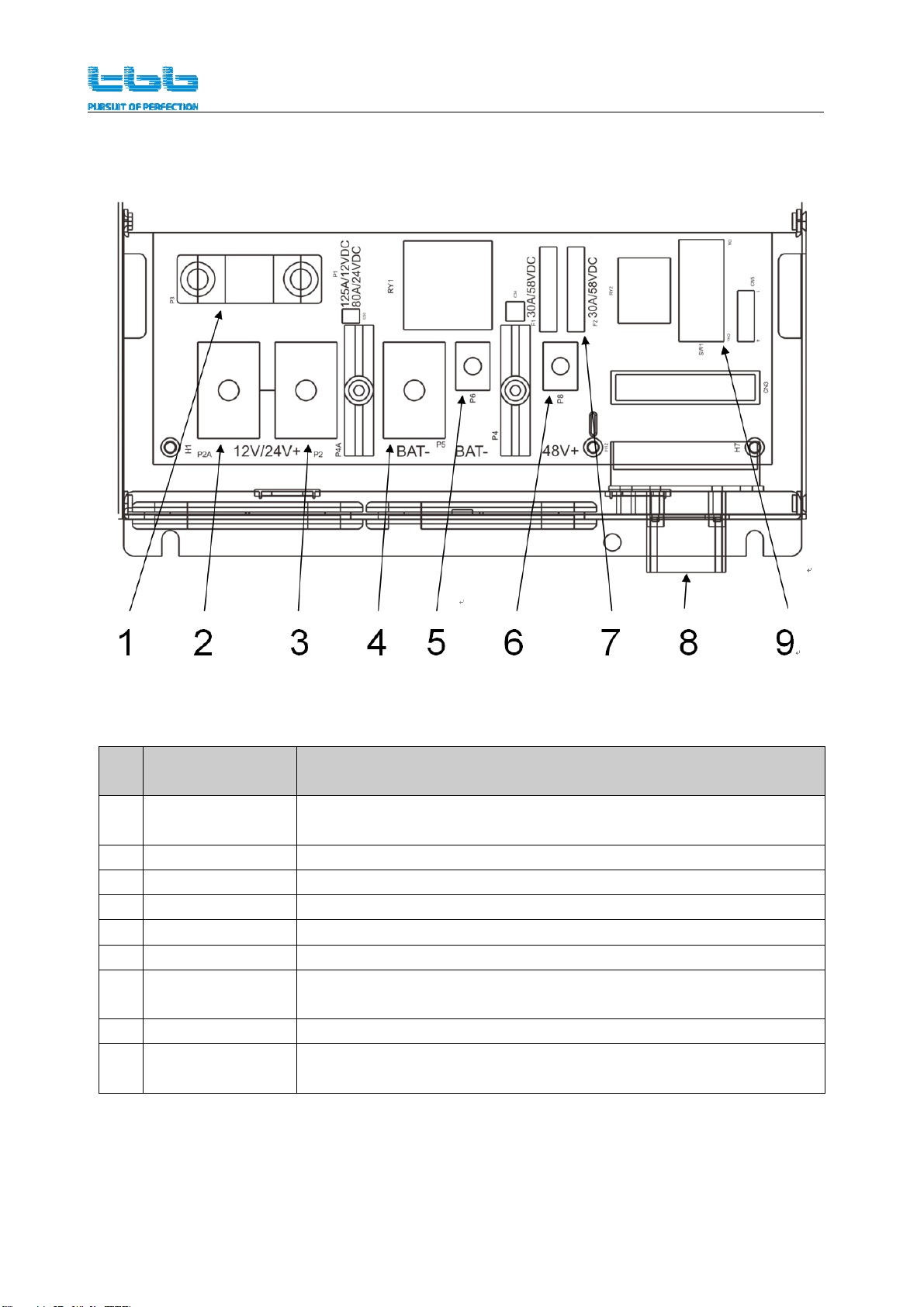
5.1Wiringdiagram
Figure5SchematicdiagramofthekeycomponentsofBi1248‐1200wiringcompartment
Table4Keymaterialsspecificationofwiringcompartment
No
.NameDescription
1Starterbattery
fuse125A/58VDC
2+12VterminalPositiveterminalfor12VDCloads,themaximumcurrentis100A
3+12VterminalPositiveterminalofstarterbattery,themaximumcurrentis200A
4‐BATterminalNegativeterminalofstarterbattery,themaximumcurrentis100A
5‐BATterminalNegativeterminalofauxiliarybattery,themaximumcurrentis25A
6+48VterminalPositiveterminalofauxiliarybattery,themaximumcurrentis25A
7COMVarioussystemsignalingwire:voltage,temperature,drycontact
etc.
8DIPswitch8‐digitDIPswitchforBi1248‐1200parametersetting
9auxiliarybattery
fuse2PCS,30A/58VDC

Bi1248‐1200UserManual
8
5.2DIPswitchdefinition
Theunitwiringcompartmenthasan8‐digitDIPswitchtosetupinformationsuchasbatterytypes,
stand‐alonemodeorsystemmode.
DIPswitchNo.DIPswitchstatusDefinitiontype
1,2BatteryType
setting
OFF,OFFAGM(default)
OFF,ONGEL
ON,OFFLFP
ON,ONOTHER
3Alternator
setting
OFFNormalalternator
ONSmartgenerator‐Euro6
4,5System
workingmode
OFF,OFFStand‐alonemode
ON,OFFN/A
OFF,ONN/A
ON,ONN/A
6
Communicatio
nprotocol
standard
OFFN/A
ONTBBstandard
7,8 X,XReserved,nofunctionnow
ForEuro6vehiclewithsmartalternator,toassuretherightcharging,itisimportantto
configurethedevice.

Bi1248‐1200UserManual
9
5.2Wiringinstruction
Forthecrimpterminalofthe12Vcable,usetheM8nutwithaflatwasherandaspring
washer.
Forthecrimpterminalofthe48Vcable,usetheM5nutwithaflatwasherandaspring
washer.
Donotoperatewithpoweron,theremightbedangerofshortcircuit,sparkingetc.
Polarityreversingoftheinputandoutputisstrictlyprohibitedanditisoutof
warranty.
ForEuro6vehiclewithsmartalternator,toassuretherightcharging,itisimportantto
configurethedeviceandconnectthisunitʹsIGNsignallinetotheIGNignitionsignalof
vehicleinstalled.
Forsafetyreasons,pleaseconnectthenegativeterminal(BAT‐)first,andthenconnectthe
positiveterminal48V+oftheauxiliarybatteryandthepositiveterminal12V+ofthestarter
batteryrespectively.
Connectoneendofthenegativecabletotheterminal“‐BAT”ofthisequipment,connectthe
otherendtothenegativebar,ornegativeterminalofstarterbatteryandthenegativeterminal
ofservicebattery.Negativebardshouldbeconnectedtothechassissecurely.
Connecttheterminalʺ+48Vʺtothepositiveterminalofthe48Vservicebatterywiththecable
specifiedfor48Vdc.
Connecttheterminalʺ+12Vʺtothepositiveterminalofstarterbatteryandalternatorwiththe
specifiedcablefor12Vdc.
Connectthevarioussamplingandcommunicationwires,includingstarterbatteryvoltage
sampling,servicebatteryvoltagesampling,batterytemperaturesamplinganddrycontact
signal.Seefollowingchapterfordetails.

Bi1248‐1200UserManual
10
5.3COMterminaldefinition
TheCOMterminalisforcommunicationsignal,voltagesamplingsignal,andadrycontactsignal.
Thepinsaredefinedasfollows.
Table5CommunicationterminaldefinitiononBIcharger
Pin
No.FunctionDescriptionDiagram
1IGNEngineignitionsignal
2VOL_BAT‐ Servicebattery
voltagesamplingline
3VOL_BAT+
4‐‐
5RS485‐ARS485communication
signal
6RS485‐B
7CAN‐HCANcommunication
signal
8CAN‐L
9DRY_DO_NO1Drycontactoutput,
normallyopencontact
10DRY_DO_NO2
11DRY_DI_NO1Drycontactinput,
normallyopencontact
12DRY_DI_NO2
13TEMP_BAT1Servicebattery
temperaturesampling
line
14TEMP_BAT1
15VOL_SBAT+Starterbatteryvoltage
sampling
16VOL_SBAT‐
Table6Wiredefinitiononplugsupplied
PinNo.WireColorFunctionDiagram
1BlackIGN
154 23678
9
12 1011141516
2BrownVOL_BAT‐
3RedVOL_BAT+
4‐ ‐
5OrangeRS485‐A
6YellowRS485‐B
7BlueCAN‐H
8WhiteCAN‐L
9GreenDRY_DO_NO1
10GreyDRY_DO_NO2
11PurpleDRY_DI_NO1
12Black‐White DRY_DI_NO2
13Black‐BlueTEMP_BAT1
14Black‐Green TEMP_BAT1
15Red‐BlackVOL_SBAT+
16Red‐WhiteVOL_SBAT‐

Bi1248‐1200UserManual
11
6. UsersInstructions
6.1CheckingandPowerOn
Pleasedoubleconfirmthealternatorvoltagematchingtheinputvoltageofthisdevice.Wrong
voltagemightdamagethedeviceanditisoutofwarranty.
Pleasedoublechecktheinputandoutputwasconnectedcorrectlytostarterbatteryand
auxiliarybatterycorrectly.
Pleasedoublecheckthepolarityofinputandoutput.Reversingpolarityoftheinputand
outputisstrictlyprohibited.
Checkifthevoltageandtemperaturecompensationlineshavebeenconnectedtothepositive
terminalofservicebattery.
Ifthegeneratorisasmartgenerator,confirmthattheDIPswitchisinthecorrectposition
accordingtoTable7.CheckiftheIGNwireisconnectedtotheIGNignitionsignalofvehicle
installed.
Checkiftheunitisinstalledfirmly.
Allabovecheckingturnontheengineandpressthepowerbutton,thecorrespondingLED
indicatorlightsupandthedevicewilldeliverchargingtoauxiliarybattery.
Turningofftheengine,thedevicewillconvert48Vdcinto12Vdctopowertheloadconnected.
Bi1248‐1200UserManual
12
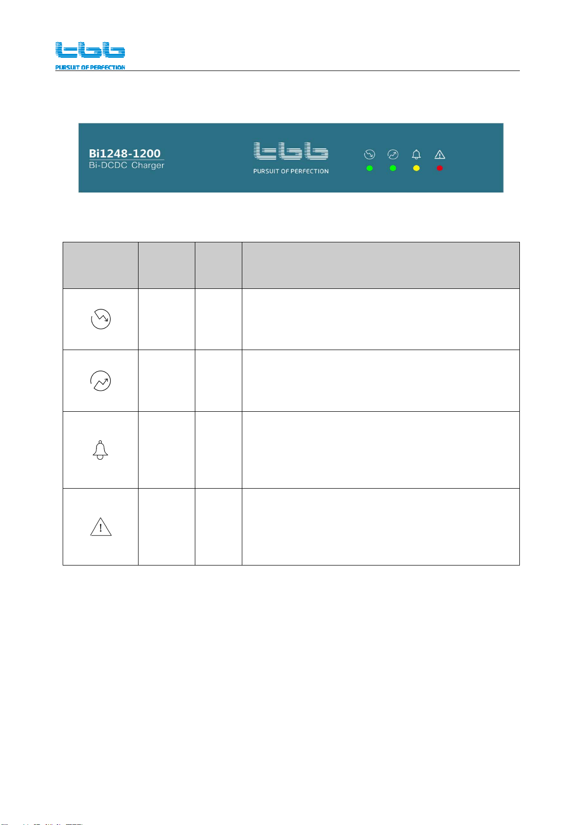
6.2Indicatordefinition
Figure6Bi1248‐1200indicatorfilmdiagram
Table6Bi1248‐1200indicatorstatusdescription
Indicator
Identificatio
n
Indicator
NameColorStatusDescription
Buck
modeGreen
On:48Vbatteryisnormal,48Vbatterycharges12V
battery
Flash:standby
Off:others
Boost
modeGreen
On:12Vbatteryisnormal,12Vbatterycharges48V
battery
Flash:standby
Off:others
AlarmOrange
Flash:overheatingoftheradiator,overtemperatureof
thebattery,overvoltageoftheservicebattery,
under‐voltageoftheservicebattery,lossof
communication,etc.
Off:others
FaultRed
Flash:Starterbatteryovervoltage,servicebattery
overvoltage,outputshortcircuit,outputovercurrent,
internalovertemperature,internalauxiliarypower
abnormality,etc.
Off:others
Bi1248‐1200UserManual
13
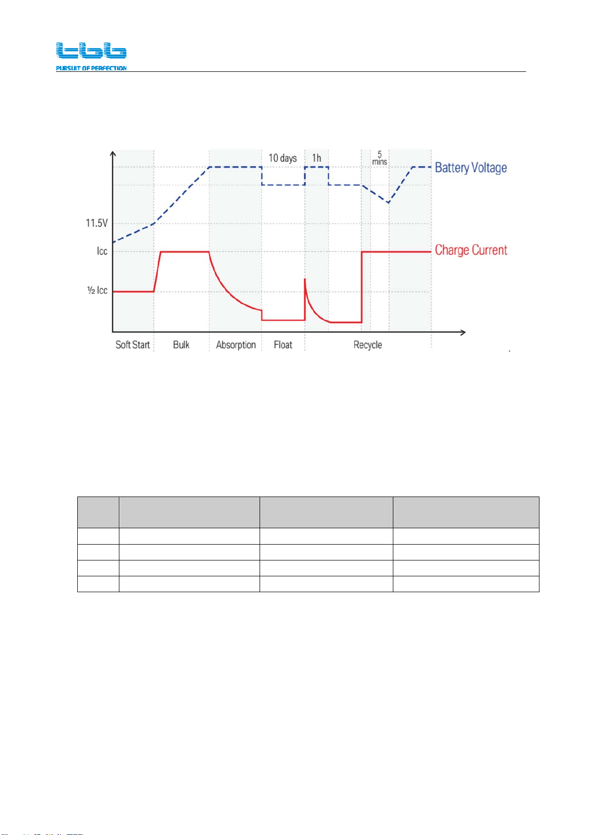
6.3Auxiliarybatterychargingcurve
Chargingcurve
Figure7TBBstandardbatterychargingcurve
Batterytypesandbulkcharging&absorptionchargingvoltage
Table8Servicebatterytypesandbulkcharging&absorptionchargingvoltage
No.BatterytypesBulkchargingvoltageAbsorptioncharging
voltage
1AGM57.6V54V
2GEL56.4V54.4V
3LFP57.6V54V
4Others56V54V

Bi1248‐1200UserManual
14
6.6Operatingtemperaturede‐ratingcurve
Thisdevicehasbuiltinintelligenttemperaturecontrolandwillreduceitsoutputpowerincaseof
highworkingtemperaturereached.
Figure8Bi1248‐1200internaltemperatureandoutputpowerderatingcurve
InternalTemperature( )℃
LoadRate(%)

Bi1248‐1200UserManual
15
7. TechnicalDataSheet
BI1248-1200
Working mode Booster mode Stepdown mode
Electrical
Input voltage 11.6~16V 42~60V
Max Input current 100A 25A
Output voltage Nominal 48Vdc, adaptive
charging 13Vdc
Charging
algorithm TBB premium II multi stage Constant Voltage
Max Output
current 25A 100A
Efficiency Max>94%,Full load>91%
Standby
consumption <2mA
Protection
Input overvoltage alarm: 14.9Vdc,protection:
16Vdc alarm: 59.6V,protection: 60Vdc
Output
overvoltage alarm: 59.6V,protection: 60Vdc alarm: 14.9Vdc,protection:
16Vdc
Over temperature 85℃85℃
Output
Shortcircuit Fuse Software
Electric Strength 2000V 2000V
Others
Working temp : -25℃- 60℃
Cooling Thermal control fan
Protection IP20
Dimension 282.8 x 200 x 85mm (LxWxH)
Installation Size 306.3 x 200 x 85mm (LxWxH)
Structure Powdered steel
Weight 3kgs

Bi1248‐1200UserManual
16
TBBPowerCo.,Ltd
Web:www.tbbpower.com
Tel:+86‐592‐5212299
Fax:+86‐592‐5796070
Email:service@tbbpower.com
Table of contents
Other TBB Batteries Charger manuals


