TBB BS1225-3 User manual


BS Smart battery charger
WARNING: HIGH VOLTAGE INSIDE
CAUTION: THE DC FUSE MUST HAVE BEENTURNED OFF BEFORE SERVICING
MADE IN CHINA

BS Smart battery charger
Disclaimer
Unless specially agreed in writing, TBB Power Co.,Ltd.
▪Take no warranty as to the accuracy, sufficiency of suitability of any technical or other information
provided in this manual or other documentation.
▪Assumes no responsibility or liability for loss or damage, whether direct, indirect, consequential or
incidental, which might arise out of the use of such information.
▪TBB offers standard warranty with its products, taking no responsibility for direct or indirect loss
due to equipment failure.
About this Manual
This manual describes our product features and provides procedure of installations. This manual is
for anyone intending to install our equipment.
General Instruction
Thanks for choosing our products and this manual were suitable for battery charger and Solar Mate
series MPPT.
This chapter contains important safety and operation instructions. Read and keep this User Guide
well for later reference.

BS Smart battery charger
Index
1. General Safety information ......................................................................................................1
2. Introduction...............................................................................................................................2
2.1 Features...............................................................................................................................2
2.1 Principle Diagram.................................................................................................................4
2.2 Naming Rules.................................................................................................................5
2.3 Product size..........................................................................................................................6
2.3.1 BS1225-3/BS1240-3/BS2412-3/BS2420-3 ..................................................................6
2.3.2 BS1210........................................................................................................................6
3. Installation.................................................................................................................................7
4. Operation...................................................................................................................................9
4.1 Front Panel...........................................................................................................................9
4.2 Side panel ..........................................................................................................................12
5. Inquiry and Configuration ......................................................................................................13
6. FAQ ..........................................................................................................................................16
6.1 Fault indicator.....................................................................................................................16
7. Specification............................................................................................................................17

BS Smart battery charger
1
1. General Safety information
Before using the charger, read all instructions and cautionary markings on the charger, the
batteries, and all appropriate sections of this manual.
Use BS battery charger only for its use as intended purpose.
Use BS battery charger only in well ventilated rooms. Do not expose the charger to rain, snow,
spray, or bilge water. To reduce risk of fire hazard, do not cover or obstruct the ventilation
openings. Do not install the charger in a zero- clearance compartment.
Always interrupt the power supply when doing repair work on the unit.
Recommend that all wiring is done by a certified technician or electrician to ensure adherence
to the local and national electrical codes applicable in your application.
Always check that existing wiring is in good condition and that wire is not undersized. Do not
operate the charger with damaged or substandard wiring.
Always use socket which are earthed and secured by earth leakage circuit breaker.
Batteries contain aggressive acids. Avoid the contact with the battery fluid agent. If a contact
with battery fluid agent should occur, then rinse the affected parts of the body or clothing etc.
with plenty cold water. It is imperative to seek medical treatment from a doctor with injuries
caused by acid.
DO NOT disassemble the charger by yourself, which may result in a risk of electrical shock or
fire. Always refer to professional electrician or our local distributor for support.
ALWAYS interrupt both theAC and DC connect when doing repair work.
DO NOT expose lead acid batteries to a lit cigarette, sparks or flames because they produce
flammable gasses and could explode.
NEVER charge NON-rechargeable battery.
Never try to charge a frozen battery. There is danger of explosion. In this case, place the
battery at a frost resistant location and wait until the battery has adapted to the ambient
temperature. Only by then, start the charging process.
This appliance can be used by children aged from 8 years and above and persons with reduced
physical, sensory or mental capabilities, or lack of experience and knowledge if they have been
given supervision or instruction concerning use of the appliance in a safe way and understand
the hazards involved. Children shall not play with the appliance. Cleaning and user
maintenance shall not be made by children without supervision.
Children should be supervised to ensure that they do not play with the appliance.
If the supply cord is damaged, it must be replaced by the manufacturer, its service agent or
similarly qualified persons in order to avoid a hazard.

BS Smart battery charger
2
2. Introduction
Batteries will be permanently damaged if they are overcharged or left discharged for a period of
time. The Trident range of smart battery chargers will continuously monitor and deliver the correct
charging profile for all battery types and conditions.The built in battery management software
ensures the batteries life expectancy is maximized.
Using the latest technology and our knowledge of batteries, the Trident range of smart battery
chaRgers are specifically designed for mobile and marine applications where on-board charging
is required.
2.1 Features
Active PFC featuring smaller and higher efficiency, max 88%
Multiple isolated outputs, including slave charger for starter battery
Automatically work as power supply or charger
Sophisticated TBB premium II multiple stages charging algorithm for lead acid battery
Suitable for lithium batteries.
Automatic temperature compensation charging.
Automatic voltage compensation charging
Programmable with software
Special silent design
TBB premium II multistage adaptive charging algorithm for lead acid battery
Fitted with multistage charging algorithm (bulk-absorption-float-recycle), BS battery charger is
designed to charge battery quickly and fully. Microprocessor controlled charging algorithm with
variable absorption charging timer guarantee the optional charging for batteries of different
discharged state.
Battrry Voltage
Charge Current
Soft Start Bulk Absorption Float Recycle
Icc
11.5V
10 days 1h 5
mins
½ Icc
Figure 1-1 charge pattern

BS Smart battery charger
3
Float charging and Recycle charging program guarantees your battery will be properly maintained
in the event of long-time fixed installation.
Battery temperature compensation
Battery temperature is a key factor in correct charging, the charging formula must be adjusted
(automatically and in real time) according to the actual battery temperature to ensure that
battery are fully charged but not overcharged or undercharged.
All charging voltages recommended by battery manufacture are in fact only applied at 20℃-
25℃.
The battery temperature and voltage sensor supplied with BS charger measures the
temperature of battery and automatically adjusts in real time to properly charge your batteries at
compensation rate of –4mv / ℃/ cell.
In case the battery temperature sensor is not present, BS charger will use 25℃as default
setting.
Voltage compensated charging
Through the battery temperature and voltage sensor, BS charger will automatically adjust its
output, compensating the voltage drop on the cable ensuring the correct charging current and
voltage is delivered the battery.
Charging current adjustable
Using the multifunctional smart button, user can choose the different charging current
according the battery capacity. We recommend the charging current set as 10%-20% of battery
capacity (I=0.1C/0.2C) for lead acid battery and 30% of battery capacity for lithium battery.
Slave battery charger for starter battery(In addition to 12V10A model)
Along with a powerful charger for stationery/service battery, BS battery charger also offers a
slave charger of max 3A to keep starter battery charged.
Special silent design
User-friendly special silent design. The fan of charger will stop working after the charging
current drop to a predetermined level for a period of them. And it will then automatically resume
working if internal temperature increases.
Using the Silent button on the remote control (optional accessory), the BS battery charger will
automatically to reduce the output of the charger and stop the fan.


BS Smart battery charger
5
2.2 Naming Rules
figure
explanation
Series name
BS
BS battery charger
Rated DC
voltage
12
12V
24
24V
Rated DC
current
10
10A
12
12A
20
20A
25
25A
40
40A
Rated AC input
N/A
220/230V
110
110V
Outputs
N/A
1+1 outputs (1 for starter battery)
3
2+1 outputs (1 for starter battery)

BS Smart battery charger
6
2.3 Product size
2.3.1 BS1225-3/BS1240-3/BS2412-3/BS2420-3
2.3.2 BS1210

BS Smart battery charger
7
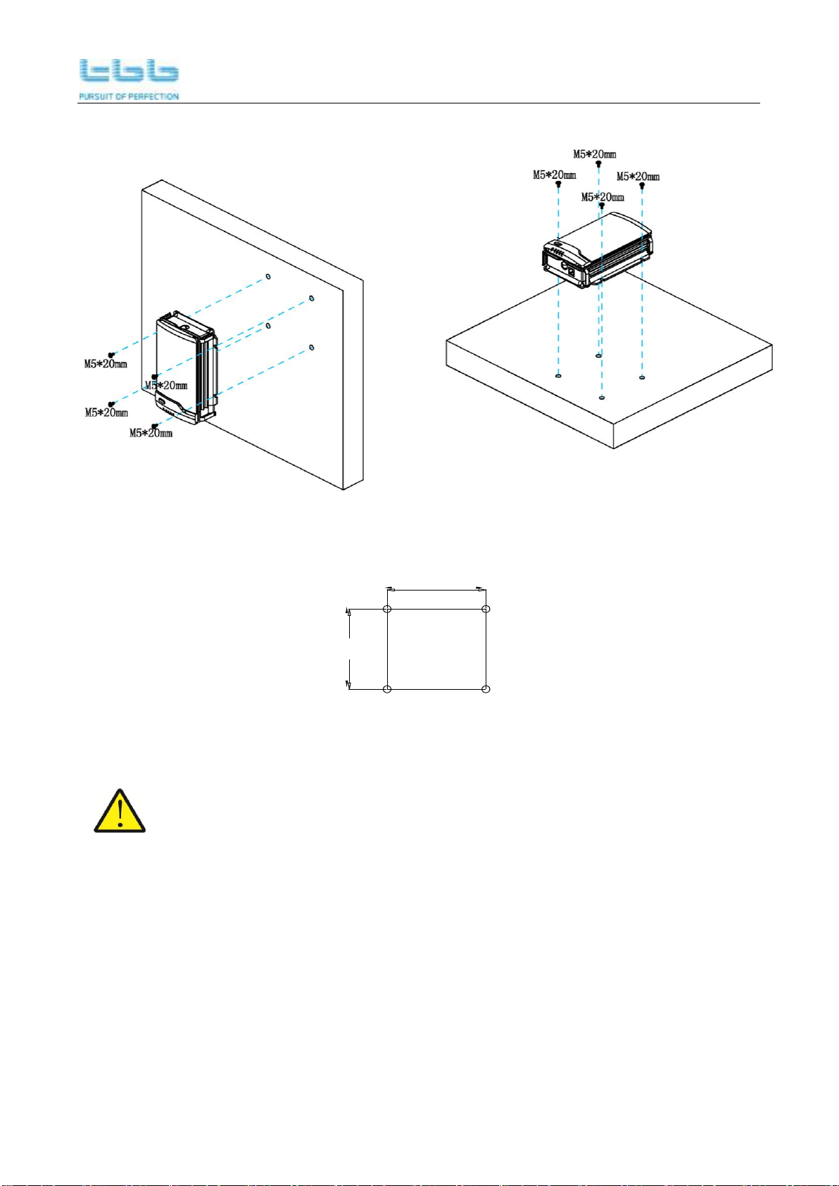
3. Installation
BS can be installed on a horizontal surface or vertically on a wall. Please see following instructions:
Hole size
BS1225-3/BS1240-3/BS2412-3/BS2420-3
BS Smart battery charger
8
Vertical Installation Horizontal Installation
Vertical Installation Horizontal Installation
M5*20mm Hole size
108
100
M5*20mm
M5*20mm
M5*20mm
M5*20mm
M5*20mm
M5*20mm
M5*20mm
Hole size
BS1210
Ensure clearance on both sides of BS unit upon installation. A recommended clearance
of 5cm on each side.

BS Smart battery charger
9
4. Operation
4.1 Front Panel
Figure 5-1 BS1225/BS1225-3/BS1240/BS1240-3
BS2412/BS2412-3/BS2420/BS2420-3
Figure 5-2 BS1210
LED2 ~ 5 represents different status of the units combined with the LED 1.
When LED1 is slow flashing, the BS charger is in the setting status.
When LED1 is quick flashing, the BS charger is in the fault indicator.
When LED1 is ON, they are the working status indicator.
No
LED
Color
Status
Description
1
LED 1
Green
ON
Charging status indication
Slow flashing (flash once every second)
Working mode setting
Blue
ON
Battery type indication
Slow flashing (flash once every second)
Battery type setting
Red
ON
Charging current indication
(In addition to 12V10A model)
Slow flashing (flash once every second)
Charging current setting
Quick flashing (flash twice every second)
Fault status indication

BS Smart battery charger
10
NO
LED
Color
Status
LED1 status
Description
2
LED2
Green
ON
ON, Green
Bulk charging
ON
ON, Blue
Battery type is AGM
ON
ON, Red
Charging current is 10A (12V40A)
Charging current is 10A (12V25A)
Charging current is 5A (24V20A)
Charging current is 3A (24V12A)
(In addition to 12V10A model)
ON
Quick flashing, Red
Output over voltage alarm
ON
Slow flashing, Blue
Battery type is set to AGM
ON
Slow flashing, Red
Charging current is set to 10A (12V40A)
Charging current is set to 10A(12V25A)
Charging current is set to 5A (24V20A)
Charging current is set to 3A (24V12A)
(In addition to 12V10A model)
3
LED3
Green
ON
ON, Green
Absorption charging
ON
ON, Blue
Battery type is GEL
ON
ON, Red
Charging current is 20A (12V40A)
Charging current is 15A (12V25A)
Charging current is 10A (24V20A)
Charging current is 6A (24V12A)
(In addition to 12V10A model)
ON
Quick flashing, Red
Battery charger over temp alarm
ON
Slow flashing, Blue
Set the battery type to GEL
ON
Slow flashing, Red
Charging current is set to 20A(12V40A)
Charging current is set to 15A(12V25A)
Charging current is set to 10A (24V20A)
Charging current is set to 6A(24V12A)
(In addition to 12V10A model)
4
LED4
Green
ON
ON, Green
Floating charging
ON
ON, Blue
Battery type is LFP
ON
ON, Red
Charging current is 30A (12V40A)
Charging current is 20A (12V25A)
Charging current is 15A (24V20A
Charging current is 9A (24V12A))
(In addition to 12V10A model)
ON
Quick flashing, Red
Output short circuit alarm
ON
Slow flashing, Blue
Set the battery type to LFP

BS Smart battery charger
11
ON
Slow flashing, Red
Charging current is set to 30A(12V40A)
Charging current is set to 20A(12V25A)
Charging current is set to 15A (24V20A)
Charging current is set to 9A (24V12A)
(In addition to 12V10A model)
5
LED5
Green
ON
ON, Green
Power supply mode
ON
ON, Blue
Battery type is WET
ON
ON, Red
Charging current is 40A (12V40A)
Charging current is 25A (12V25A)
Charging current is 20A (24V20A)
Charging current is 12A (24V12A)
(In addition to 12V10A model)
ON
Quick flashing, Red
Battery not connected or reverse polarity
alarm
ON
Slow flashing,
Green
Set to power supply mode
OFF
Slow flashing,
Green
Set to battery charger mode
ON
Slow flashing, Blue
Set the battery type to WET
ON
Slow flashing, Red
Charging current is set to 40A (12V40A)
Charging current is set to 25A (12V25A)
Charging current is set to 20A (24V20A)
Charging current is set to 12A (24V12A)
(In addition to 12V10A model)
NO
Label
Description
6
Charging state
7
Battery type
8
Charging Current(In addition to 12V10A model)

BS Smart battery charger
12
4.2 Side panel
Figure 4-3 BS1225/BS1225-3/BS1240/BS1240-3/
BS2412/BS2412-3/BS2420/BS2420-3
No.
Label
Description
1
Input
AC input socket
2
Starter Battery
Starter battery connector
3
Output
Service battery connector
4
Sensor
Battery temperature and voltage sensor connector
5
Monitor
Remote panel connector
6
Setting/Select
Setting button
Figure 4-4 BS1210
No.
Label
Description
1
Input
AC input socket
2
Output
Service battery connector
3
Sensor
Battery temperature and voltage sensor connector
4
Setting/Select
Setting button
BS Smart battery charger
13
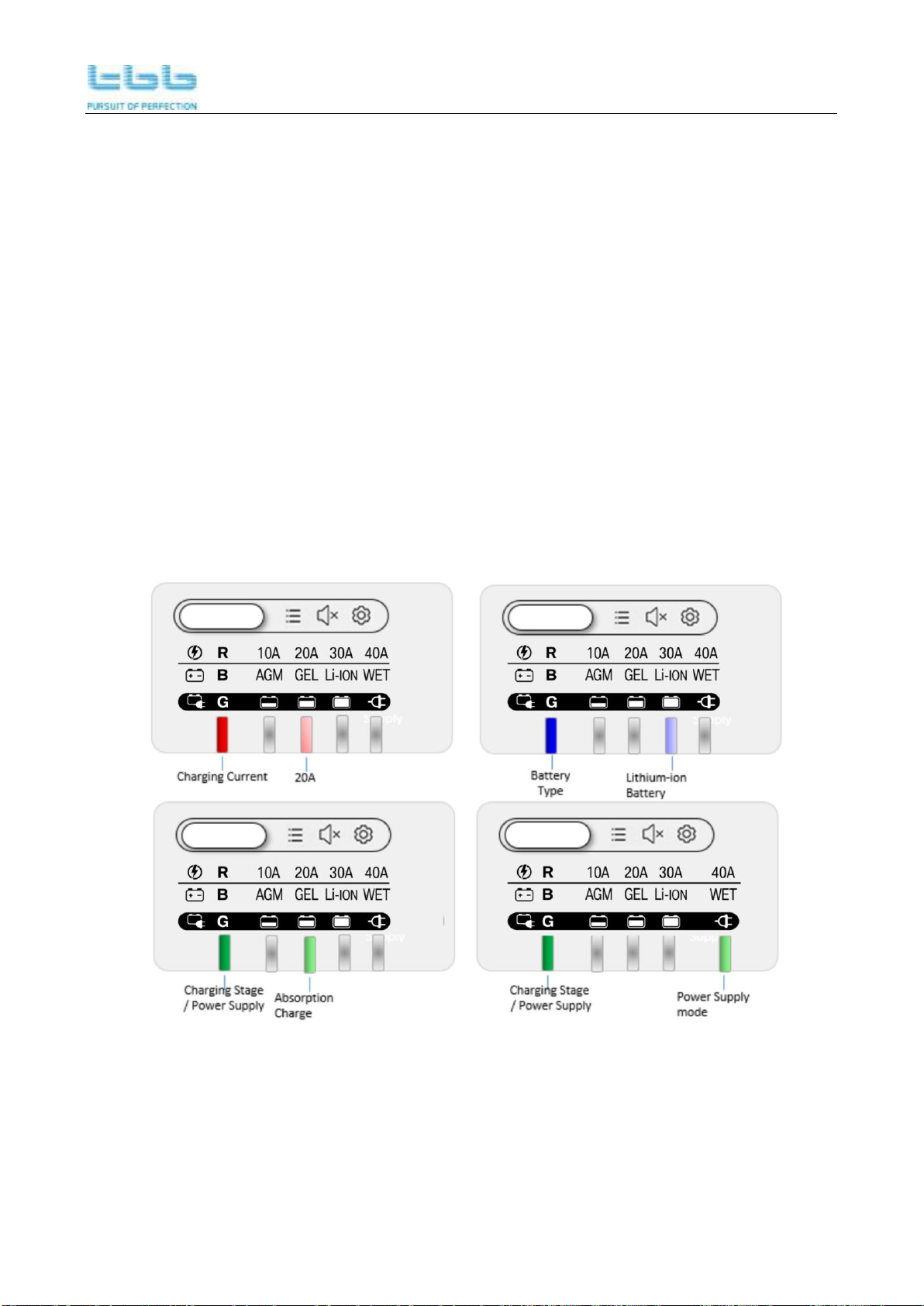
5. Inquiry and Configuration
There is a multifunction smart button for you to set the battery charger or check the settings. The
LED displays the charging status by default, you can check the battery type and output current
setting by short pressing the button.
Please follow the following steps to set the charger.
1. Please short press the button for entering into Battery Type Display mode or Charger Current
Display mode.
2. Then, long press the main button for 3s, you can enter into the setting mode.
3. By pressing the button, you can set the battery type or charger output current.
4. After the setting, please long press the button to confirm the setting.
As a reminder, different colors of LED are designed for various setting.
BLUE = battery type setting (AGM, GEL, LFP, WET)
RED = charging current setting (In addition to 12V10A model)
GREEN = working mode setting, battery charger or power supply
Examples
Figure 4-1 BS1225/BS1225-3/BS1240/BS1240-3
BS2412/BS2412-3/BS2420/BS2420-3

BS Smart battery charger
14
Figure 4-2 BS1210
When the LED1 is green, it is in the indication of charging status. You can also set this battery
charger into a power supply by pressing this button for 3sec entering into setting mode.
Status
LED 1
LED2
LED3
LED4
LED5
Green
Green
Bulk
Absorption
Float
Power supply
BS Smart battery charger
15
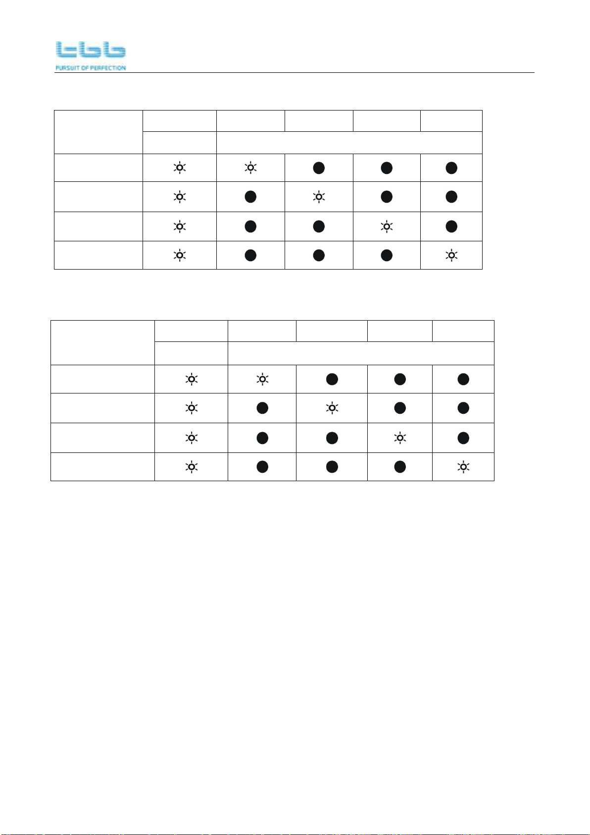
If the LED1 is blue, it is in the indication of battery type. You can also set the battery type after long
press the button for 3secs.
Battery type
LED1
LED2
LED3
LED4
LED5
BLUE
Green
AGM
GEL
LFP
WET
If the LED1 is red, it is in the indication of battery charger power. You can also set the power after
long press the button for 3secs. (In addition to 12V10A model)
Charging current
percentage
LED1
LED2
LED3
LED4
LED5
Red
Green
25%
50%
75%
100%

BS Smart battery charger
16
6. FAQ
6.1 Fault indicator
When the LED1 is red and flashing, it is fault indication. Please refer the below table for details. If
the user switch on the AC grid before the connection of battery, there will be “Battery not connected”
indication. To exit this alarm, short press the main button after well connecting the battery.
Fault
LED
LED2
LED3
LED4
LED5
Flash, Red
Green
O/P over voltage
Charger over temp
O/P short circuit
Battery not connected
or reverse polarity
This manual suits for next models
4
Table of contents
Other TBB Batteries Charger manuals


Popular Batteries Charger manuals by other brands

Leviton
Leviton evr-green EVR30-B1C installation guide

Universal Power Group
Universal Power Group 24BC8000-L-1 Specification sheet

Anywhere Cart
Anywhere Cart AC-MANAGE user guide

Galaxy Audio
Galaxy Audio ANY SPOT AS-DCTVMBP user guide

Xenotronix
Xenotronix MHTX7 Series user manual

IOTA
IOTA DLS SERIES owner's manual


InvisQi
InvisQi Invisible Wireless Charger User Instructions and Installation Guide

Halo
Halo Pocket Power 7800 operating instructions

Insignia
Insignia NS-GWU1303-C Quick setup guide

Mastervolt
Mastervolt CombiMaster 120V Series User and installation manual

Hama
Hama 14056 Operating instruction

Hitachi
Hitachi uc 3sfl Handling instructions