TBEI Rugby LR-26C User manual

TRUCK BODIES & EQUIPMENT INTERNATIONAL, Inc.
Website: www.rugbymfg.com
E-mail: [email protected]
Phone: 1-800-869-9162 036268
MODEL LR-26C, LR-623,
LR-28A, & LR-2355 HOIST
INSTALLATION AND
OPERATION MANUAL
To Be Filled In By Installer
HoistSerial#:
Pump Installation and
Operation Manual #:
InServiceDate:
Dealer:
Address:
City,StateZIP:
Dealer Phone Number:
Use this manual ONLY if installing or operating a model LR-26C, LR-623, LR-28A, or LR-2355 hoist. This
manual should be kept in the glove compartment of the truck for reference when needed.
Original Revision: January 18, 2007
Current Revision: C August 14, 2007

Model LR-26C, LR-623, LR-28A, & LR-2355 Hoist Installation and Operation Manual
Stock No. 036268
Page 2 of 27
"HYDRAULIC SYSTEM"
The hydraulic system supplied with a given hoist manufactured by TBEI-Rugby is made up of
components (pump, valves, reservoir, hoses, cylinder, etc.) that are designated to be compatible with
each other.
WARNING: If you substitute hydraulic components, it is your responsibility to BE SURE they are
compatible with the other components supplied by TBEI-Rugby. Incompatible
hydraulic components may cause failure of the hoist that, in turn, could damage the
vehicle, damage other property, and cause human injury or death.
All TBEI-Rugby's liability and warranty for a given hoist will be voided, if it is determined by TBEI-
Rugby, that substituted hydraulic components were incompatible with those supplied by TBEI-Rugby.
Several hoist parameters are given in the following table, these parameters are given as a general
guide. To ensure component compatibility, consult TBEI-Rugby.
HOIST MODEL
LR-26C
LR-623
LR-28A
LR-2355
“MAXIMUM”
HYDRAULIC FLOW
RATE (GPM)
9 GPM 18 GPM
“MAXIMUM”
PRESSURE FOR
RAISING PORTION OF
DUMP CYCLE (PSI)
3200 PSI 3200 PSI
“MAXIMUM”
PRESSURE FOR
LOWERING PORTION
OF DUMP CYCLE (PSI)
1000 PSI 1000 PSI
WARNING: Adjusting the hydraulic pressure to more than the recommended setting may cause the
hoist to fail during the dumping of a load. This could cause damage, serious injury, or
death. Never adjust the pressure on your own. Consult the manufacturer if the
hydraulic pressure is in question. Have only a qualified person set the hydraulic
pressure. Never adjust the pressure to more than the recommended amount.
NOTE: A manual for the hydraulic system is supplied separate from this manual. Refer to the
hydraulic system manual for details on the installation and operation of the hydraulic
system.

Model LR-26C, LR-623, LR-28A, & LR-2355 Hoist Installation and Operation Manual
Stock No. 036268
Page 3 of 27
"WARNINGS"
WARNING: Installing or operating this hoist without first understanding the proper installation and
operation procedures can lead to serious injury or death. Always read and understand
fully all installation and operation manuals before installing or operating this
equipment.
WARNING: Welding, oxy-fuel cutting, or grinding sparks can cause fuel to ignite that in turn can
lead to injury or death. Always take adequate steps to avoid ignition of fuel from fuel
tanks when welding, grinding, or oxy-fuel cutting during equipment installation.
WARNING: Heat from the truck's exhaust system can cause hydraulic component failure and may
lead to a fire that could cause injury or death. Always install equipment in locations
where heat from the exhaust system will not damage any hydraulic component.
WARNING: Being under a raised body can result in serious injury or death should the body
unexpectedly descend. Never position yourself or allow others to position themselves
under a loaded body. Always prop the unloaded body up using the body prop or body
props supplied. Remember body props are to be used only on an unloaded body.
When two props are provided, both props must be used.
WARNING: Malfunctioning equipment can cause property damage, injury or death. Always have
faulty equipment repaired before continuing its use. Consult the manufacturer if
required.
WARNING: Overloading of a body can cause vehicle or body component damage or an accident
which may cause injury or death. Never exceed the gross vehicle weight (GVW) or the
gross axle weight (GAW) rating of your vehicle.
WARNING: The inadvertent shorting of the vehicle's electrical supply can cause a fire or equipment
damage that could lead to injury or death. Always disconnect the vehicle battery prior
to installing, servicing, or repairing the power unit.
WARNING: Damage to brake lines during equipment installation, or installing bolts or equipment in
such a way that the line will rub and become damaged can lead to brake failure which
can cause an accident and can lead to severe injury or death. Always take adequate
steps to prevent brake line damage during installation and isolate brake lines from
installed equipment.
WARNING: Connecting the hoist to a hydraulic system with more pressure (psi) or flow (gpm) than
is recommended by the hoist manufacturer can cause the hoist to fail during the
dumping of a load. This could lead to damage, serious injury, or death. Be sure you
have the correct pressure and flow.

Model LR-26C, LR-623, LR-28A, & LR-2355 Hoist Installation and Operation Manual
Stock No. 036268
Page 4 of 27
&$
:%
0
$3352;
67$1'$5'
02817,1*
5(9(56(
02817,1*
5($5
+,1*(
FIGURE 1
IMPORTANT: NR stands for Not Recommended. Contact TBEI-Rugby Engineering before using in
an application listed as NR.

Model LR-26C, LR-623, LR-28A, & LR-2355 Hoist Installation and Operation Manual
Stock No. 036268
Page 5 of 27
TABLE A
LR-26C APPLICATION CHART
BODY
LENGTH OVERHANG
CAPACITY
40° DUMP
ANGLE
CAPACITY
45° DUMP
ANGLE
CAPACITY
50° DUMP
ANGLE
10’ 12” 18.5 TONS 16.8 TONS
10’ 0” 16.6 TONS 14.8 TONS 13.4 TONS
11’ 12” 18.4 TONS 16.5 TONS 14.9 TONS
12’ 24” 20.8 TONS 18.5 TONS 16.8 TONS
12’ 12” 16.6 TONS 14.8 TONS 13.4 TONS
12’ 0” NR 12.3 TONS 11.2 TONS
13’ 42” 27.7 TONS 24.7 TONS 22.4 TONS
13’ 30” 20.8 TONS 18.5 TONS 16.8 TONS
13’ 24” 18.4 TONS 16.5 TONS 14.9 TONS
14’ 42” 23.7 TONS 21.2 TONS 19.2 TONS
14’ 36” 20.8 TONS 18.5 TONS 16.8 TONS
14’ 30” 18.4 TONS 16.5 TONS 14.9 TONS
14’ 24” NR 14.8 TONS 13.4 TONS
14’ 12” NR 12.3 TONS 11.2 TONS
15’ 48” 23.7 TONS 21.2 TONS 19.2 TONS
15’ 42” 20.8 TONS 18.5 TONS 16.8 TONS
15’ 36” NR 16.5 TONS 14.9 TONS
16’ 48” NR 18.5 TONS 16.8 TONS
16’ 42” NR 16.5 TONS 14.9 TONS
LR-26C REVERSE STANDARD
M DUMP ANGLE M
102.25” 40° 104.25”
91.25” 45° 93.25”
82.50” 50° 84.50”
DUMP CLASS: 50
CONVERSION CLASS: E
7.13” Mounting Height
6” long beams recommended
Capacities are based on the following:
1. Water level non-diminishing loads.
2. The hydraulic relief pressure set at the maximum 3,200 psi (see page 2 of this manual).
IMPORTANT: Because of variations in applications, the data contained in this sheet is provided only
as a general guide.
IMPORTANT: NR stands for Not Recommended. Contact TBEI-Rugby Engineering before using in
an application listed as NR.

Model LR-26C, LR-623, LR-28A, & LR-2355 Hoist Installation and Operation Manual
Stock No. 036268
Page 6 of 27
TABLE B
LR-623 APPLICATION CHART
BODY
LENGTH OVERHANG
CAPACITY
40° DUMP
ANGLE
CAPACITY
45° DUMP
ANGLE
CAPACITY
50° DUMP
ANGLE
10’ 6” 19 TONS 18 TONS
11’ 18” 22 TONS 20 TONS
12’ 6” 18 TONS 16 TONS 14 TONS
13’ 18” 20 TONS 17 TONS 16 TONS
13’ 24” 22 TONS 19 TONS 18 TONS
13’ 42” 29 TONS 27 TONS
14’ 18” 18 TONS 16 TONS 14 TONS
14’ 30” 22 TONS 19 TONS 18 TONS
14’ 36” 25 TONS 22 TONS 20 TONS
16’ 18” 15 TONS 13 TONS 12 TONS
16’ 24” 16 TONS 14 TONS 13 TONS
16’ 42” 22 TONS 19 TONS 18 TONS
18’ 18” 13 TONS 11 TONS 10 TONS
18’ 30” 15 TONS 13 TONS 12 TONS
18’ 42” 18 TONS 16 TONS 14 TONS
LR-623 REVERSE STANDARD
M DUMP ANGLE M
117.75” 40° 119.00”
105.25” 45° 106.50”
95.25” 50° 96.50”
DUMP CLASS: 50
CONVERSION CLASS: F
8.13” Mounting Height
7” long beams recommended
Capacities are based on the following:
1. Water level non-diminishing loads.
2. The hydraulic relief pressure set at the maximum 3,200 psi (see page 2 of this manual).
IMPORTANT: Because of variations in applications, the data contained in this sheet is provided only
as a general guide.

Model LR-26C, LR-623, LR-28A, & LR-2355 Hoist Installation and Operation Manual
Stock No. 036268
Page 7 of 27
TABLE C
LR-28A APPLICATION CHART
BODY
LENGTH OVERHANG
CAPACITY
40° DUMP
ANGLE
CAPACITY
45° DUMP
ANGLE
CAPACITY
50° DUMP
ANGLE
12’ 12” 17.2 TONS
12’ 0” 15.7 TONS 14.4 TONS
13’ 12” 17.1 TONS 15.7 TONS
14’ 24” 18.9 TONS 17.2 TONS
14’ 12” 17.6 TONS 15.7 TONS 14.4 TONS
14’ 0” 15.0 TONS 13.5 TONS 12.3 TONS
15’ 36” 21.0 TONS 19.2 TONS
16’ 42” 23.5 TONS 21.0 TONS 19.2 TONS
16’ 36” 21.1 TONS 18.9 TONS 17.2 TONS
17’ 48” 23.4 TONS 21.0 TONS 19.2 TONS
17’ 42” 21.1 TONS 18.9 TONS 17.2 TONS
17’ 36” 19.2 TONS 17.1 TONS 15.7 TONS
18’ 48” 21.1 TONS 18.9 TONS 17.2 TONS
18’ 42” 19.2 TONS 17.1 TONS 15.7 TONS
LR-28A REVERSE STANDARD
M DUMP ANGLE M
144” 40° 146”
129” 45° 131”
118” 50° 120”
DUMP CLASS: 60
CONVERSION CLASS: F
8.13” Mounting Height
7” long beams recommended
Capacities are based on the following:
1. Water level non-diminishing loads.
2. The hydraulic relief pressure set at the maximum 3,200 psi (see page 2 of this manual).
IMPORTANT: Because of variations in applications, the data contained in this sheet is provided only
as a general guide.

Model LR-26C, LR-623, LR-28A, & LR-2355 Hoist Installation and Operation Manual
Stock No. 036268
Page 8 of 27
TABLE D
LR-2355 APPLICATION CHART
BODY
LENGTH OVERHANG
CAPACITY
40° DUMP
ANGLE
CAPACITY
45° DUMP
ANGLE
CAPACITY
50° DUMP
ANGLE
10’ 12” 25 TONS
11’ 12” 22 TONS
12’ 12” 20 TONS
16’ 24” 20 TONS 18 TONS 16 TONS
16’ 36” 24 TONS 22 TONS 20 TONS
18’ 24” 17 TONS 15 TONS 14 TONS
18’ 36” 20 TONS 18 TONS 16 TONS
18’ 42” 22 TONS 20 TONS 18 TONS
19’ 36” 18 TONS 17 TONS 15 TONS
19’ 40” 20 TONS 18 TONS 16 TONS
20’ 24” 15 TONS 14 TONS 12 TONS
20’ 30” 16 TONS 15 TONS 13 TONS
20’ 36” 17 TONS 15 TONS 14 TONS
20’ 42” 18 TONS 17 TONS 15 TONS
LR-2355 REVERSE STANDARD
M DUMP ANGLE M
115” 40° 117”
102” 45° 105”
93” 50° 95”
DUMP CLASS: 60
CONVERSION CLASS: G
8.13” Mounting Height
7” long beams recommended
Capacities are based on the following:
1. Water level non-diminishing loads.
2. The hydraulic relief pressure set at the maximum 3,200 psi (see page 2 of this manual).
IMPORTANT: Because of variations in applications, the data contained in this sheet is provided only
as a general guide.

Model LR-26C, LR-623, LR-28A, & LR-2355 Hoist Installation and Operation Manual
Stock No. 036268
Page 9 of 27
"INSTALLATION INSTRUCTIONS"
1. Mark the location for the rear hinge. This location should be immediately behind a truck cross
member, approximately 32" behind the center of the rear axle on single axle trucks. Refer to
Figure 1 and the charts for the specific hoist model you are installing.
NOTE: If a distance of 38" is exceeded between the rear hinge and the center of the rear axle,
additional reinforcement of the truck frame will be required.
2. Referring to Figure 2, cut a notch as shown.

Model LR-26C, LR-623, LR-28A, & LR-2355 Hoist Installation and Operation Manual
Stock No. 036268
Page 10 of 27
3. Position the rear hinge angle in the notch cut in Step 2. The rear hinge angle is 38 1/16" wide
and should be centered side to side in the notch as illustrated in Figure 3. Weld the rear hinge angle to
each of the truck chassis frame rails.
NOTE: This hinge assembly is designed for a truck longsill spacing of 34" and is not
recommended for any other width.
NOTE: The distance between the rear hinge shaft center and the saddle center is referred to as
the "M" dimension. In Table A & B, the "M" dimension for several dump angles are
tabulated.
0,1,080
0,1,080
)25:$5'029(0(170$,17$,1&/($5$1&(,17+,6$5($72$92,'
,17(5)(5(1&(%(7:((1+2,67$1'&52660(0%(5
127,&(29$/6$''/(78%(+$66/,')25:$5'
+2,67:,//6/,'($+($'$%287
+2,67326,7,21,1),567)(:'(*5((62)/,)7&<&/(
7+(6,=($1'6+$3(2)&52660(0%(56
6+2:1$5()25,//8675$7,21385326(621/<
6$''/(%5$&.(76+$9(%((15(029('
,17+(),*85(6)25,//8675$7,21385326(6
+2,67326,7,21,10,''/(2)/,)7&<&/(
+2,67326,7,21%()25(%(*,11,1*2)/,)7&<&/(
0$,17$,16+2:1',0(16,21672$//2:5220
)257+(+2,6772527$7()5((/<'85,1*/,)7
&<&/(
127,&(+2:7+(+2,670867%(,167$//('68&+
7+$77+(29$/6$''/(78%(,66/,'$6)$5
5($5:$5'$63266,%/(:+(17+(+2,67,6'2:1
WARNING: During the first degrees of the dump cycle, the hoist lower link will move forward if in
the standard mounting configuration. The lower link will move rearward if in the
reverse mounting configuration. Therefore, it is important to keep the areas illustrated
in Figure 4 open to allow this hoist movement. Failure to do this will cause the hoist to
not operate as intended and may damage the hoist and/or other truck components.
FIGURE 4

Model LR-26C, LR-623, LR-28A, & LR-2355 Hoist Installation and Operation Manual
Stock No. 036268
Page 11 of 27
NOTE: Moving the hoist rearward or forward along the truck frame will affect the hoist's
performance. A forward movement will reduce the dump angle and will increase
capacity while a rearward movement will increase the dump angle and reduce capacity.
NOTE: If an obstruction can not be cleared by moving the hoist forward or rearward, the hoist
may be reverse mounted as shown in Figure 1.
4. Locate the hoist on the truck frame, making sure to center the hoist right and left, and to square
the hoist with the truck frame. This hoist is designed to rest on the truck frame as shown in
Figure 1. A small portion of the hoist extends below the truck frame level. The hoist may
have to be moved forward or rearward to avoid obstructions below the frame level.
5. Slide a lock collar onto each lifting shaft. Slide a lifting shaft with collar into each end of the
hoist lifting tube. See Figure 5.
FIGURE 5
6. When the hoist is positioned, place a mounting angle under each side of the hoist saddle.
Secure each mounting angle to the truck frame by drilling three 17/32" dia. holes and installing
three 1/2" bolts, three 1/2" lock washers, and three 1/2" nuts. Torque all 1/2” fasteners to 90 ft-
lb. See Figure 6.
FIGURE 6
6$''/($66(0%/<
758&.)5$0(
02817,1*$1*/(
758&.)5$0(
187
%2/7
/2&.
:$6+(5

Model LR-26C, LR-623, LR-28A, & LR-2355 Hoist Installation and Operation Manual
Stock No. 036268
Page 12 of 27
7. Weld each saddle bracket to the corresponding mounting angle. See Figure 6.
NOTE: Do not weld the hoist or mounting angle to the truck frame.
NOTE: The hoist saddle must set directly on the truck frame. If rivet interference is
encountered, counter sink the rivet head into the hoist saddle.
8. Position and secure the liner (sleeper) to the truck frame. The LR-26C hoist requires at least 7
1/8" of clearance above the truck frame. As an example, if 6" long beams are on the truck
body, a liner of at least 1 1/8" will be required to gain enough room, 7 1/8", for mounting the
LR-26C. Similarly, a LR-623, LR-28A, or LR-2355 requires 8 1/8" of clearance.
9. Position the body with the long beams (just long beams if they are separate from the body)
onto the truck frame.
NOTE: A clearance of at least 2" is required between the truck cab and the closest point on the
truck body.
10. Position the rear hinge brackets against the long beams. Once in position, weld the rear hinge
brackets to the body long beams by welding all edges where the rear hinge bracket contacts the
long beam.
IMPORTANT: The saddle tube is oblong, allowing the hoist to slide front to back. This is part of
the anti-kickup design. Before performing the next step, the oval saddle tube must be
slid as far rearward as possible as shown in Figure 4. Failure to do this will cause the
"anti-kickup device" to function improperly, causing damage to the hoist, truck body,
and/or other truck components.
Model LR-26C, LR-623, LR-28A, & LR-2355 Hoist Installation and Operation Manual
Stock No. 036268
Page 13 of 27
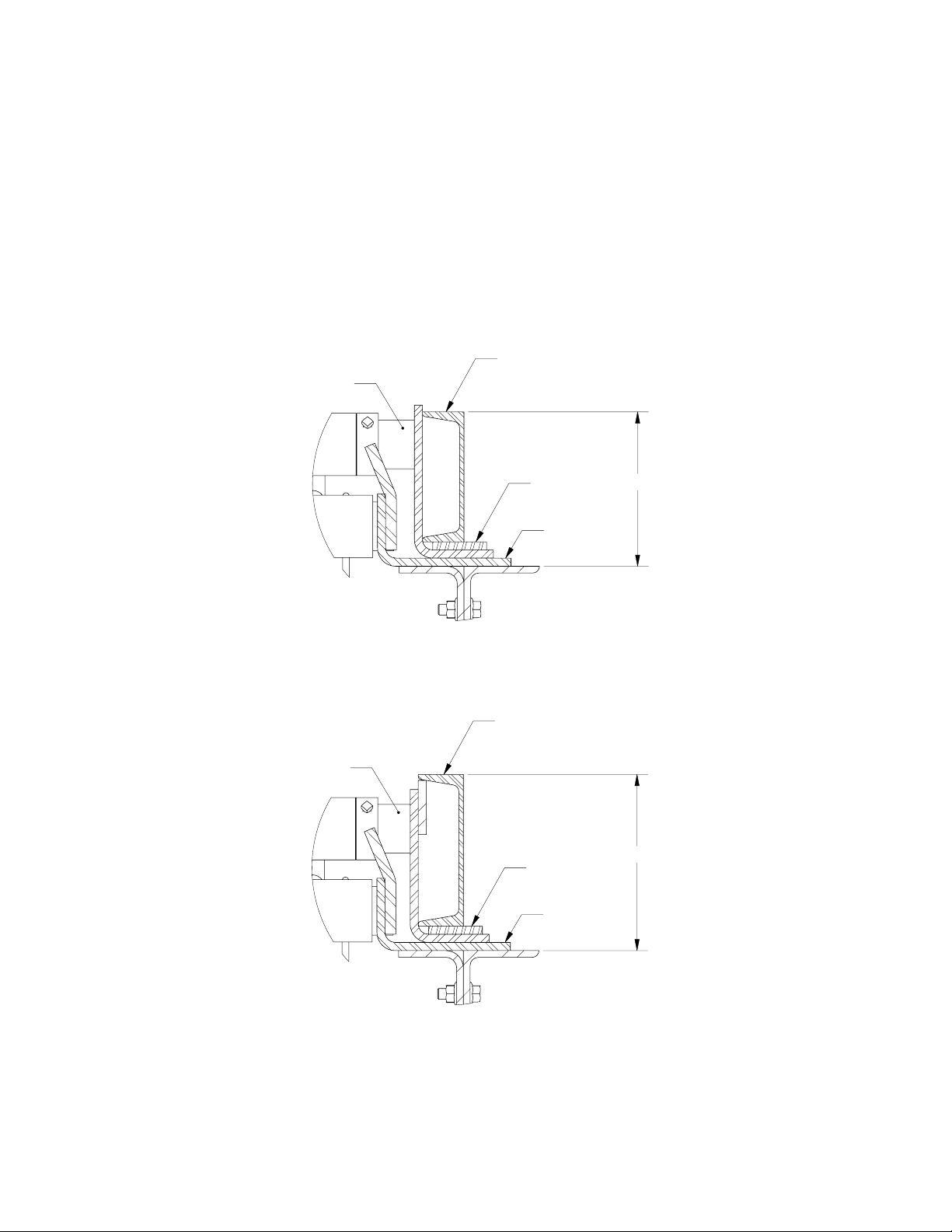
11. Position a lifting shaft sub-assembly and flats next to each channel long beam. Refer to figure
7. Slide each of the lifting shafts all the way against the inside of the long beam. Push the
hoist so that the oval saddle tube is slid as far rearward as possible (see Figure 4). Weld the
lifting shaft angles to secure the shaft to the long beam as shown in Figure 7. With the shaft
secured, slide the lock collars against the hoist lifting tube and lock them there by tightening
the setscrew (see Figure 5 and 7). Torque the setscrew to 24 ft-lb.
/,)7,1*6+$)7
68%$66(0%/<
6758&785$/&+$11(/
/21*6,//
[
[)/$7
+2,67
6$''/(
+2,6772%2'<$77$&+0(17'(7$,/)256758&785$/&+$11(//21*6,//
$1'02817,1*+(,*+7
/,)7,1*6+$)7
68%$66(0%/<
6758&785$/&+$11(/
/21*6,//
[
[)/$7
+2,67
6$''/(
+2,6772%2'<$77$&+0(17'(7$,/)256758&785$/&+$11(//21*6,//
$1'02817,1*+(,*+7
FIGURE 7

Model LR-26C, LR-623, LR-28A, & LR-2355 Hoist Installation and Operation Manual
Stock No. 036268
Page 14 of 27
12. Install all grease fittings. For grease fitting locations in the hoist, refer to Figure 12. Torque
each grease fitting to 70 in-lb. Grease all grease fittings on both the hoist and the rear hinge.
13. Install the body prop. Refer to the “BODY PROP” section of this manual.
14. Install the hydraulic system. Cycle the hoist several times to rid the hydraulic circuit of air.
IMPORTANT: Several different types of hydraulic components are used to power this hoist. All
hydraulic systems supplied by TBEI-Rugby have an installation and operation manual
included with them. For installation and operation information, refer to the Installation
and Operation Manual for your particular hydraulic components. BE SURE to read
and understand this manual and the installation and operating instructions included with
the hydraulic system before you attempt to operate this hoist.
WARNING: Installing or operating this hoist without first understanding the proper installation and
operation procedures can lead to serious injury or death. Always read and understand
fully all installation and operation manuals before installing or operating this
equipment.
NOTE: Before operating the hoist, read the "OPERATION" section of this manual
WARNING: If it is necessary to work on the hoist or body while in the raised position, ALWAYS
block the unloaded body up securely with the body prop or body props.
15. Place a complete operation manual in the glove compartment of the truck. This manual MUST
BE available for reference by the operator when needed.
WARNING: If the hydraulic system used to power this hoist was supplied by TBEI-Rugby, an
operation manual will be included with the hydraulic components. The operation
manual for this hydraulic system MUST BE supplied to the operator.
WARNING: If the hydraulic system used to power this hoist was supplied by someone other than
TBEI-Rugby, an operation manual for this hydraulic system MUST BE obtained and
supplied to the operator.
16. Install all decals. Refer to "DECAL LOCATION" section of this manual.

Model LR-26C, LR-623, LR-28A, & LR-2355 Hoist Installation and Operation Manual
Stock No. 036268
Page 15 of 27
"BODY PROP"
NOTE: In order to comply with paragraph 10 of Federal Regulation #1926.601, all TBEI-
Rugby hoists will be sold with one body prop. It is the responsibility of the installer to
determine whether one body prop is sufficient. The following information will help in
making that determination.
The body prop is designed for use only when the body is empty. The purpose of the
body prop is to hold an empty body in the raised position when performing
maintenance or inspection on the hoist, body, or any component that requires working
under an empty body.
Some applications may require 2 or more body props to support the empty body. To
determine how many body props your application requires, refer to the following
information.
WARNING: Being under a raised body can result in serious injury or death should the body
inadvertently descend. Never position yourself or allow others to position themselves
under a loaded body. Always prop the unloaded body up using the body prop/s
supplied. Remember, body props are to be used only on an unloaded body. When
two props are provided, both props must be used.
WARNING: Do not use body prop to support a loaded body!
WARNING: Do not perform maintenance under a raised body without first blocking the empty body
up with the body prop/s.
WARNING: Do not use a body prop that is bent or otherwise damaged. A damaged body prop will
have a reduced holding capacity, and may break when used to hold up the body. This
could cause serious injury or death. Replace a damaged body prop before using it.
WARNING: Be sure to install the body prop according to the “INSTALLATION OF BODY
PROP” section of this manual.
The following is a step by step procedure to determine how many body props are required for this
application.
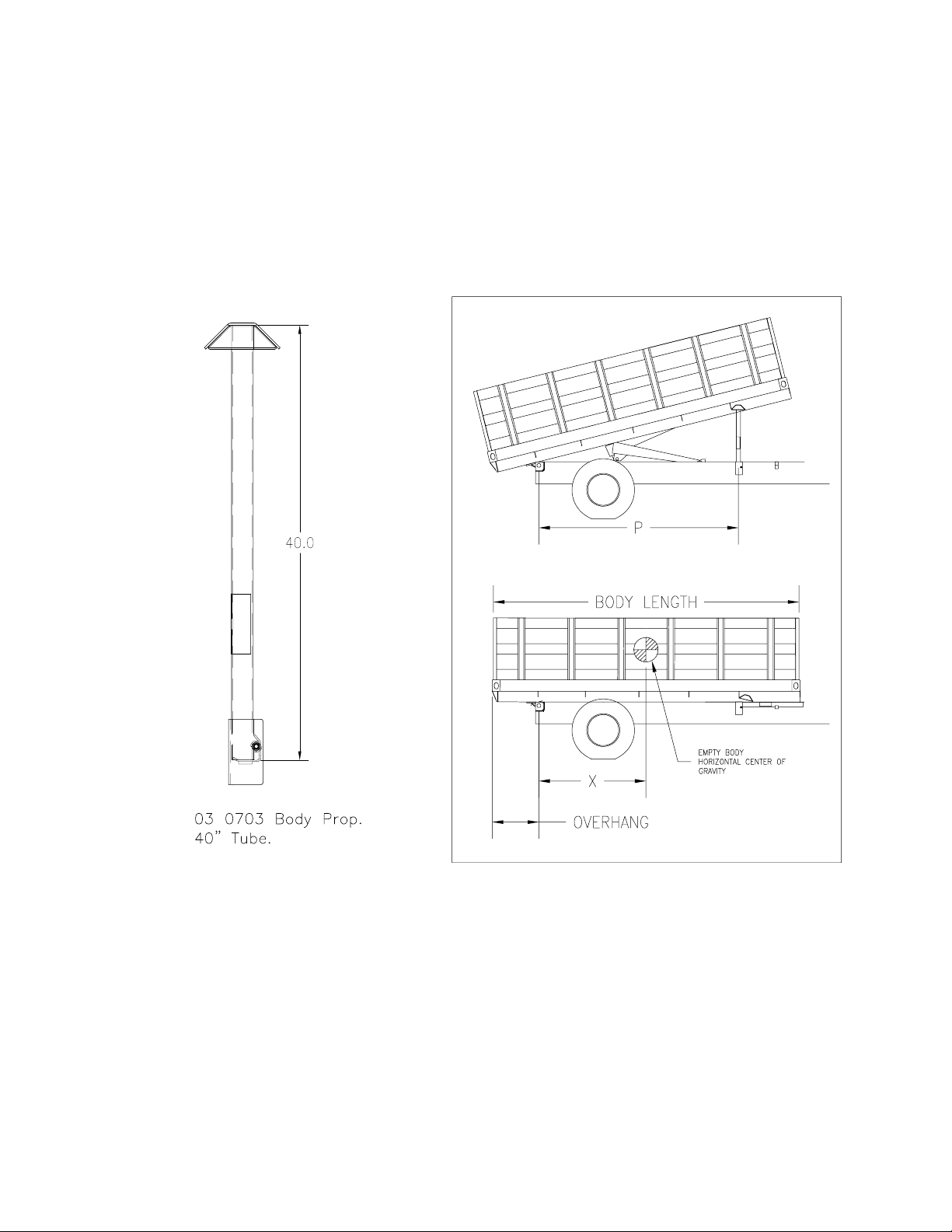
1. The TBEI-Rugby Part Number 03 0703 body prop is to be used with this hoist. Determine if
this is the body prop you have by referring to Figure 8.
2. Determine the "P" value referring to Figure 9. The "P" value is the horizontal distance between
the rear hinge and the prop.
Model LR-26C, LR-623, LR-28A, & LR-2355 Hoist Installation and Operation Manual
Stock No. 036268
Page 16 of 27
3. Determine the "X" value referring to Figure 9. The "X" value is the horizontal distance
between the body center of gravity and the rear hinge when the body is empty and down. Be sure to
include any items attached to the body such as toolboxes or other structures when determining the
center of gravity.
FIGURE 8 FIGURE 9
4. On the left side of Chart 1, pick the "P" value for your application. On the top of the same
chart, pick the "X" value for your application. Below the "X" value and to the right of the "P" value is
listed an amount of weight. This represents the maximum weight that the body can weigh and be
supported by only one body prop. If the body weights more than the amount listed, 2 body props will
be required. Contact TBEI-Rugby to order another body prop.
NOTE: If the body weighs more than 2 times the amount listed, another type of body prop
with more weight capacity will be required, as 2 body props will not support this
empty body.
Model LR-26C, LR-623, LR-28A, & LR-2355 Hoist Installation and Operation Manual
Stock No. 036268
Page 17 of 27
CHART 1
03 0703 BODY PROP CAPACITY
Distance Rear Hinge - Center of Gravity (X)
0-36 37-48 49-60 61-72 73-84 85-96 97-108 109-120 121-132 133-144
42-47 6,100 4,500 3,500 2,800 2,300 2,000 1,700 1,500 1,300 1,100
48-53 6,600 4,800 3,800 3,000 2,500 2,100 1,800 1,600 1,400 1,200
54-59 7,200 5,200 4,100 3,300 2,800 2,300 2,000 1,800 1,600 1,400
60-65 7,700 5,700 4,400 3,600 3,000 2,600 2,200 1,900 1,700 1,500
66-71 8,300 6,100 4,800 3,900 3,300 2,800 2,400 2,100 1,900 1,700
72-77 8,900 6,600 5,100 4,200 3,500 3,000 2,600 2,300 2,000 1,800
78-83 9,500 7,000 5,500 4,500 3,800 3,200 2,800 2,500 2,200 2,000
84-89 10,200 7,500 5,900 4,800 4,000 3,500 3,000 2,700 2,400 2,100
90-95 10,800 7,900 6,200 5,100 4,300 3,700 3,200 2,800 2,500 2,300
96-101 11,400 8,400 6,600 5,400 4,600 3,900 3,400 3,000 2,700 2,400
102-107 12,100 8,900 7,000 5,800 4,900 4,200 3,700 3,200 2,900 2,600
108-115 12,700 9,400 7,400 6,100 5,100 4,400 3,900 3,400 3,100 2,800
114-119 13,400 9,900 7,800 6,400 5,400 4,700 4,100 3,600 3,200 2,900
120-125 14,000 10,400 8,200 6,700 5,700 4,900 4,300 3,800 3,400 3,100
126-131 14,700 10,900 8,600 7,100 6,000 5,200 4,500 4,000 3,600 3,300
132-137 15,300 11,400 9,000 7,400 6,300 5,400 4,700 4,200 3,800 3,400
138-143 16,000 11,800 9,400 7,700 6,500 5,600 5,000 4,400 4,000 3,600
144+ 16,600 12,300 9,800 8,000 6,800 5,900 5,200 4,600 4,100 3,700
Distance Rear Hinge - Body Prop (P)
Maximum Body Weight per Body Prop
EXAMPLE: Using a 12' body that has an empty weight of 6,000 pounds. Body is installed with a
18" overhang. The prop is located 84" forward of the rear hinge. Assume the center of gravity
is 72" from the rear of the body. Subtract the overhang to get X=54". Using P=84-89, X=49-
60, the maximum body weight is 5,900 pounds. This application needs 2 body props.
Remember, this is an example only, and in no way means that this hoist is or is not acceptable
to use in this application.
Model LR-26C, LR-623, LR-28A, & LR-2355 Hoist Installation and Operation Manual
Stock No. 036268
Page 18 of 27
"INSTALLATION OF BODY PROP"
NOTE: The following steps are to be used as a guideline when installing the body prop. Since
trucks will vary according to their design it is not possible to be specific about every
aspect of the body prop installation.
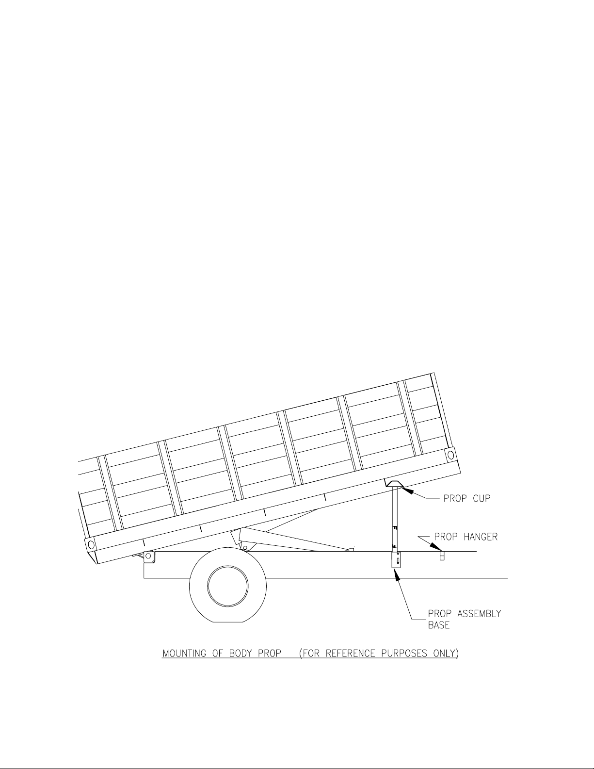
1. Once the TBEI-Rugby hoist has been installed, raise the hoist up and temporarily block the
body up. Position the prop assembly against the truck frame as illustrated in Figure 9.
2. Fasten the body prop assembly base to the truck frame.
3. Position and fasten the prop hanger to the truck frame. Hanger must be installed so that when
the body is down the body prop leg will not bounce out of the hanger.
4. Position and weld the prop cup on the body as illustrated in Figure 10.
NOTE: To raise and lower body prop, see the "OPERATION OF BODY PROP" section of
this manual.
FIGURE 10

Model LR-26C, LR-623, LR-28A, & LR-2355 Hoist Installation and Operation Manual
Stock No. 036268
Page 19 of 27
"DECAL LOCATION"
Two “DANGER” decals, as shown on this page are supplied with each hoist. These decals should be
positioned as shown in Figure 11. The part number of the “DANGER” decal is 03 6039.
FIGURE 11
WARNING: Missing or damaged decals can cause incorrect or unsafe operation of the hoist, which
can cause accidents, which may cause serious injury or death. If any decals are missing
or damaged, they must be replaced.
To obtain replacement decals, contact your TBEI-Rugby dealer or call 1-701-776-5722 or 1-800-869-
9162.
Model LR-26C, LR-623, LR-28A, & LR-2355 Hoist Installation and Operation Manual
Stock No. 036268
Page 20 of 27
"LUBRICATION"
IMPORTANT: All grease fittings should be greased at least twice annually. Refer to Figure 12 for
grease fitting locations. Failure to grease hoist will result in hoist failure. Hoist failure
due to lack of grease is not covered by the warranty.
IMPORTANT: Refer to installation and operation manual of the hydraulic system for hydraulic
system lubrication instructions.
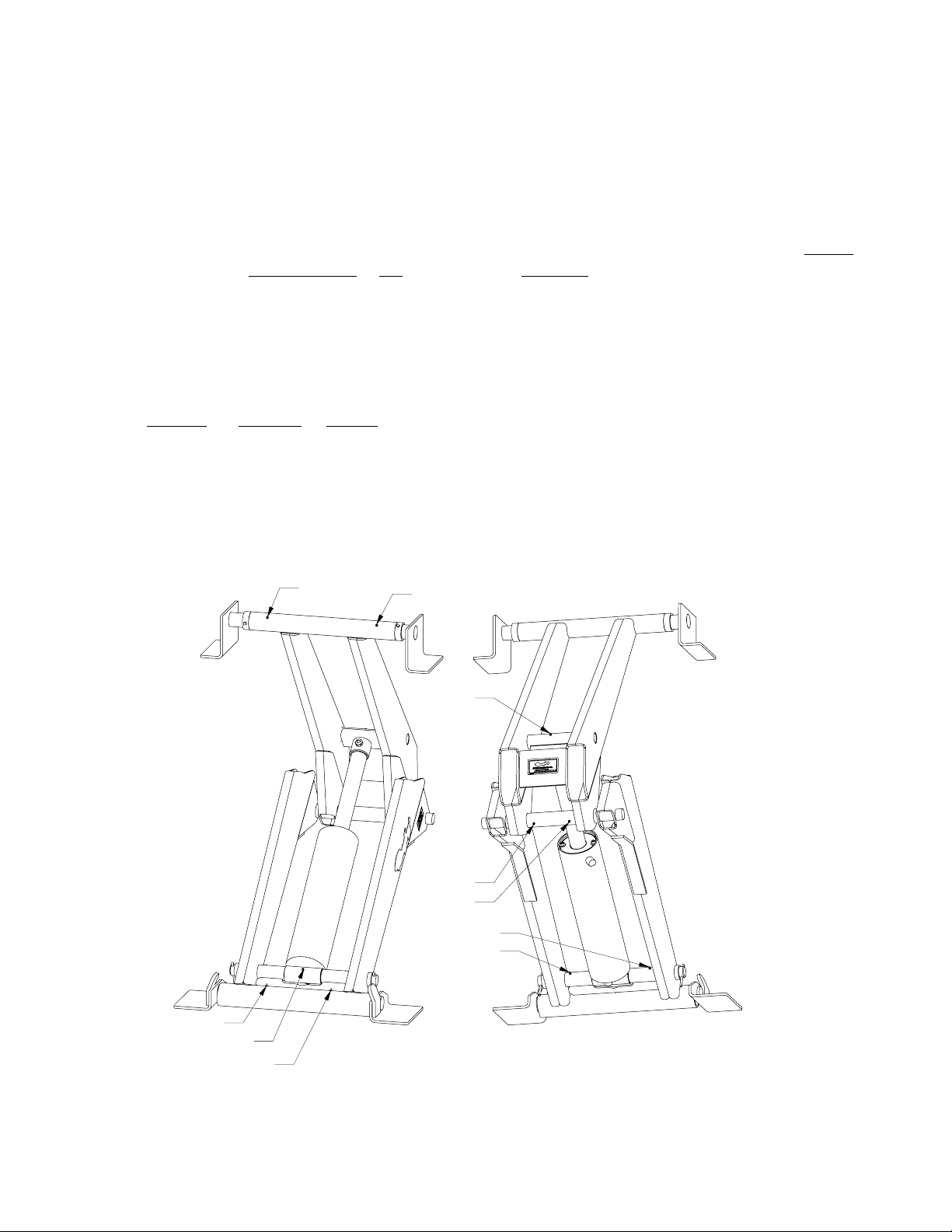
1. Grease all of the grease fittings in the hoist frame itself. Apply grease until excess grease can
be seen coming out the ends of the tubes. Refer to Figure 12 for grease fitting locations.
Replace any missing or broken grease fittings.
2. Grease the two grease fittings in the truck rear hinge.
3. Check oil level in the pump reservoir every time the oil is changed in the truck engine.
REMEMBER keep the oil clean. An annual oil change can prevent contaminants from
ruining your pump and hoist cylinder.
FIGURE 12A: LR-26C, LR-623, or LR-28A GREASE ZERK LOCATIONS
10 ZERKS TOTAL
This manual suits for next models
3
Other TBEI Chain Hoist manuals


Popular Chain Hoist manuals by other brands

Frequenz
Frequenz 400-100 instruction manual

Verlinde
Verlinde Stagemaker SR25 2508 M1 B owner's manual

Columbus McKinnon
Columbus McKinnon CM LODESTAR Operating, Maintenance & Parts Manual

ACCO Brands
ACCO Brands Accolift instructions

CarlStahl
CarlStahl CondorLift CLLH0008F user manual

AMH
AMH X5SL02250 manual


Verlinde
Verlinde Stagemaker SR25 owner's manual

Hubbell
Hubbell CHANCE 3011S Operating and service instructions

Bannon
Bannon 57065 owner's manual

Edbro
Edbro CX 11 Operator's manual

Coffing Hoists
Coffing Hoists ELC Series Operating, Maintenance & Parts Manual

CMCO
CMCO Yale VSIII 0,25/1 operating instructions