Frequenz 400-100 User manual

Instruction Manual
Frequenz400-100 / Frequenz400-140
REV:01


Contents
1. General Safety Information...........................................................................................3
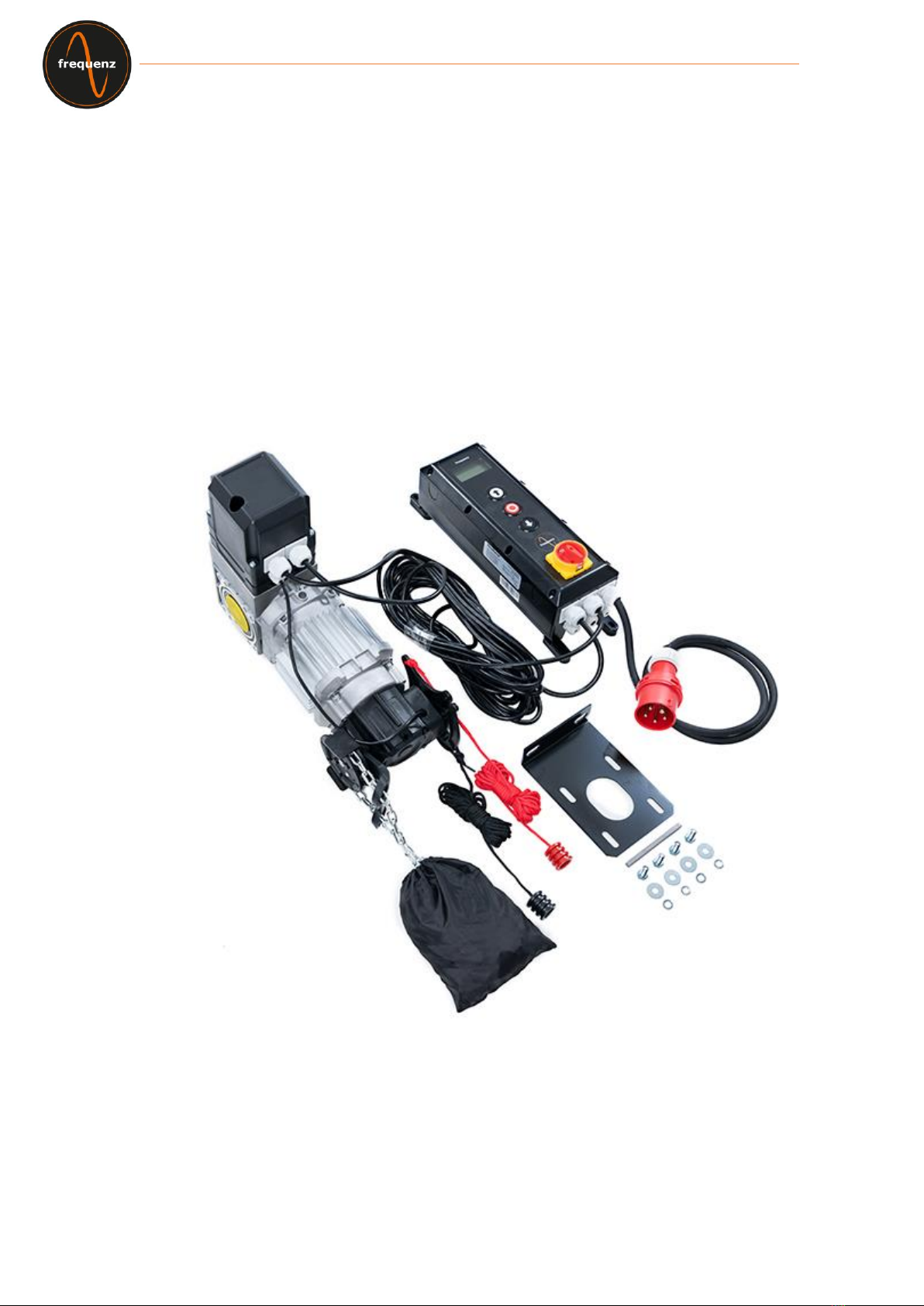
2. Product Description ......................................................................................................4
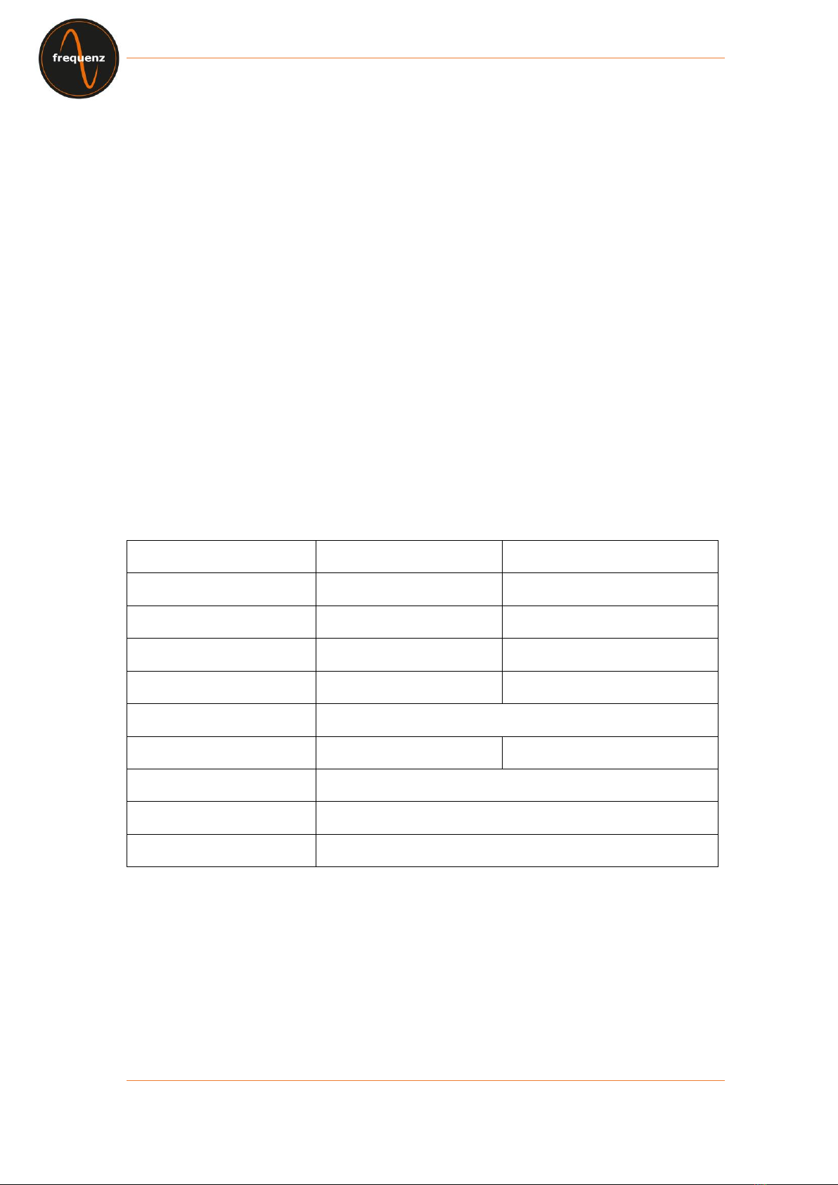
3. Technical Data ...............................................................................................................4
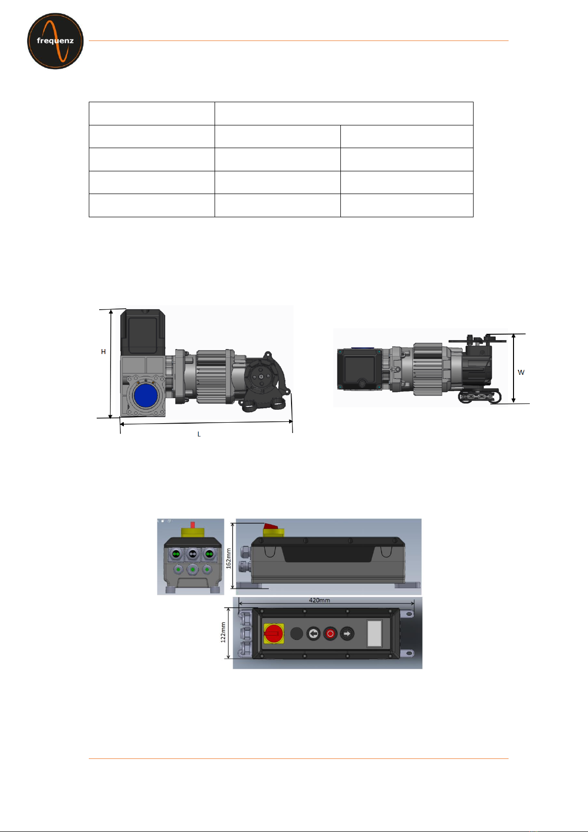
4. Drawing of appearance and dimension ......................................................................5
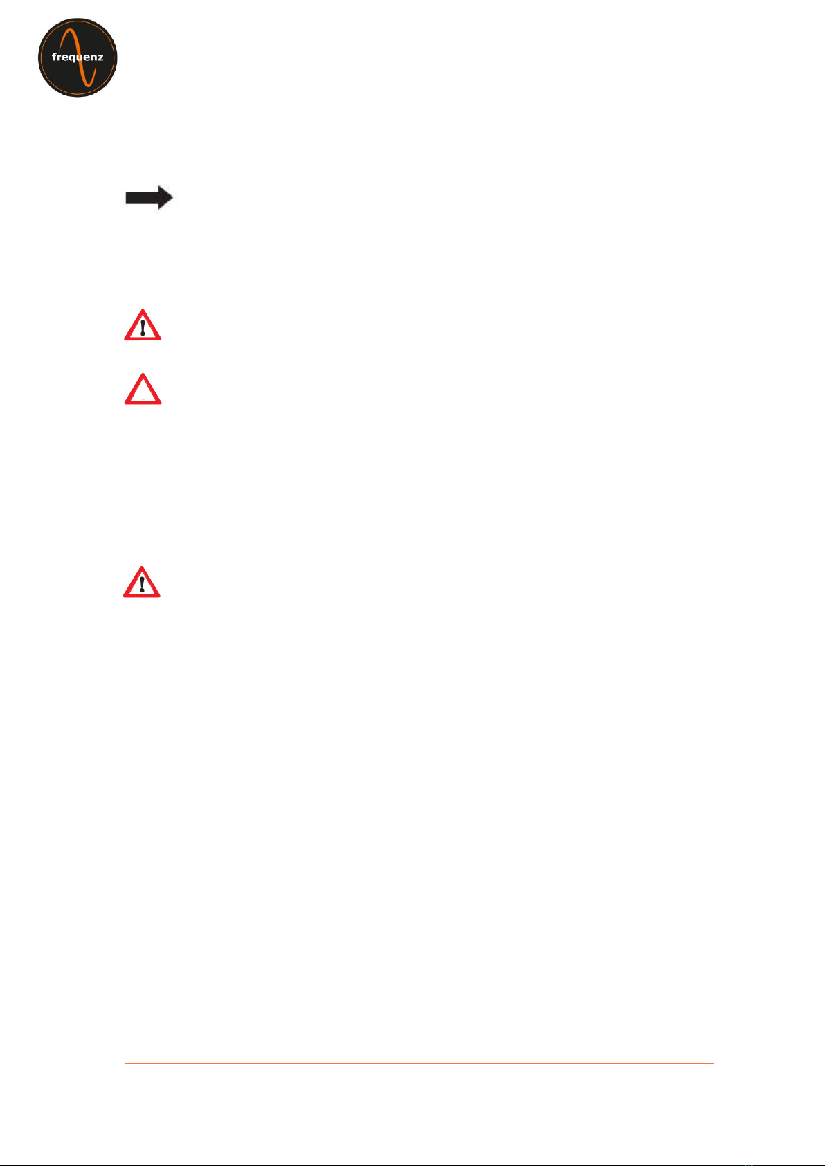
5. Warnings –Symbols .....................................................................................................6
6. Safety information of operation...................................................................................6
7. Safety information for installation...............................................................................7
8. Proper Use......................................................................................................................8
9. Scope of delivery...........................................................................................................8
10. Components introduction ........................................................................................9
11. Layout of control unit................................................................................................10
12. Installation..................................................................................................................11
13. Wiring..........................................................................................................................14
14. Operator Programming.............................................................................................19
14.1 Main Menu ................................................................................................................19
14.2 Set Password...........................................................................................................20
14.3 Load Settings...........................................................................................................21
14.4 Door Positions.........................................................................................................22
14.5 Safety Devices .........................................................................................................25
14.6 Operation Mode .......................................................................................................27
14.7 Inputs / Outputs.......................................................................................................28
14.8 Automatic Closing...................................................................................................30
14.9 Service......................................................................................................................31
14.10 Expert Settings ......................................................................................................32
14.11 Motor Settings........................................................................................................33
15. Error Code Table........................................................................................................34
16. EC Declaration of Incorporation ..............................................................................36

- 3 -
1. General Safety Information
⚫The door operator may only be used under the conditions described in these
instructions. Any other use will be considered improper usage and therefore
dangerous. The manufacturer is not liable for damage resulting from improper,
incorrect or inappropriate usage.
⚫Failure to observe the information contained in these instructions may lead to personal
or material damage. The instructions must be passed on to all future users and
operators of the door operator.
⚫Only use the door operator if no maintenance or adjustment measures are required to
do so. Disconnect the operator from the power supply for cleaning or maintenance.
⚫Only use the door operator if the entire area of movement is fully visible. During
operation, be aware of other people who may be within the operating range of the
product or who may enter this area. Do not drive or walk underneath the door while it
is moving.
⚫Do not use the door operator to lift up objects and/or people.
⚫Ensure that children are kept away from the area around the door.
⚫Children over the age of 8 and persons with reduced physical, sensory or mental
capabilities may operate the door operator when supervised or if they have been
instructed in the safe handling of the equipmentand are aware of the associated risks.
⚫Keep remote controls and/or other controls out of reach of children to prevent the
accidental activation of the door operator.
⚫Cleaning work on the door operator or the door or any maintenance measures may
only be performed by children when supervised.
Dispose the operator according to your local environmental regulations.
Electrical parts must not be disposed as domestic waste !

- 4 -
2. Product Description
The door operator has been developed for industrial doors.
The door operator can be equipped with the following additional safety devices, such as:
-Photocells,Light curtains,Safety edges
-Radar
-Loop detector
-Remote control,Push buttons,Pull switches
-Traffic light
The door operator is operated via the control unit.
You can choose different operating settings for the operator (e.g. automatic, semi-
automatic or hold to run).
3. Technical Data
Model
Frequenz 400-100
Frequenz 400-140
Rated Voltage/Frequency
400V 3-phase/ 50Hz
400V 3-phase / 50Hz
Rated input power in KW
0.8
1.1
Torque in Nm
100
140
Speed in RPM
30
30
Frequency converter
NA
Diameter hollow shaft in mm
25.44mm
25.44/31.75mm
Max cycles per hour
35c/h
Emergency release
Chain hoist
Limit setting of door travel
Digital encoder

- 5 -
4. Drawing of appearance and dimension
Hyper lift-model
Frequenz 400-100
Frequenz 400-140
Door operator L*W*H(mm)
431*180*280
488*180*280
Control box L*W*H(mm)
420*122*162
420*122*162
Packing L*W*H(mm)
573*510*200
573*510*200
Door operator
Control box

- 6 -
5. Warnings –Symbols
Note: Technical information must be observed
Fig. 1 Number of a figure
Caution: Warns of a risk to a person / risk of injury
Warning: Warns of a risk to material / risk of damage
6. Safety information of operation
The door may only operated if:
⚫Conformity in accordance with Machinery Directive 2006/42/EC was declared
following assembly.
⚫The door complies with the standards EN 12605, EN 12604 and DIN EN 13241-1.
⚫The door operator has been assembled in accordance with EN 12453, EN 12445 and
EN 12635.
⚫Any additionally installed safety equipment is functioning properly.
⚫There is an internally operated emergency release for garages that have no second
access.
⚫Any pass door set within the door is equipped with a safety device that prevents
switch-on while the door is open.
⚫The emergency release cannot be caught on any vehicle parts (e.g. roof structures).
⚫It is insured that the installation is conform with the national safety regulations.
Keep the instruction manual at a safe place!

- 7 -
7. Safety information for installation
Important:
The door must move easily and be functional and well-balanced in accordance with the
manufacturer's specifications.
It must be possible to open and close the door by hand easily.
Assembly must be carried out by trained and specialized personnel.
Electrical installation work must only be performed by authorized and specialized
personnel.
The suitability and bearing capacity of the supporting structure of the building in which the
door operator is to be installed must be checked and confirmed by expert personnel.
The door operator must be securely fastened at all the mounting points provided. The
mounting material must be chosen according to the material characteristics of the
supporting structure to ensure that a minimum tensile force of 900 N can be withstood.
If these requirements are not fulfilled, the door operator may fall down or the door may
move without control. This means there is a risk of personal injury or material damage.
When mounting the door operator, it must be secured by appropriate means against falling
until it is completely and safely attached.
Observe the relevant occupational health and safety regulations during the installation.

- 8 -
8. Proper Use
This door operator is suitable for use with balanced sectional doors and sectional
doors equipped with spring-break protection and/or safety catch.
The maximum dimensions given in the technical data must be complied with.
Before installing the door operator, any existing locking mechanisms for the door must be
disassembled or taken out of operation.
Use in an explosion-proof environment is not permitted.
Any other use above and beyond this is considered as improper use.
All of the below activities performed without the express written approval of the
manufacturer:
⚫Expansions or modifications
⚫Use of non-original replacement parts
⚫Performance of repairs by persons or operators that have not been authorized by the
manufacturer may result in the loss of the warranty.
No liability can be accepted for damages that result from the following causes:
⚫Technical defects on the door to be operated and structural deformations occurring
during operation
⚫Improper maintenance of the door
⚫Failure to observe the operating instructions
9. Scope of delivery
1
Door operator with emergency release (chain)
2
Control unit with main switch
3
Torque bracket
4
Assembly fasteners
5
External power cable with plug
6.
Signal cable
7.
Internal power cable

- 9 -
10. Components introduction
1
Motor
2
Emergency release (Chain)
3.
Gear box
4.
Emergency release deactivate cord
5
Emergency release activate cord
6
LCD display
7
“UP” button
8
“STOP” button
9
“DOWN” button
10
Main switch
11
Power plug
1
2
4
5
3
6
7
8
9
10
11

- 10 -
11. Layout of control unit
Frequenz 400V

- 11 -
12. Installation
The door operator shown is similar to sectional dooroperators type with chaindrive. Unless
described otherwise, the assembly steps also apply to high speed door operators with
crank.
Preparation for installation
Risk ofpersonal injury and/or material damage due toelectrical voltage. Have aspecialized
electrician open and close the cover for the motor controller.
Determine the installation location of the door operator
The door operator must be positioned 100% above the door drive shaft.
Make sure that neither the emergency manual operation chain nor crank
(depending on version) can impair the normal operation of the door (clearance)
and that they can be used at any time.
12.1 Install the torque bracket
Install the torque bracket (3) as shown in Fig. 1. Make sure that the drive shaft for the door
can extend at least 135 mm (dimension A) in the door operator to be installed.
Fig. 1

- 12 -
12.2 Install the feature key
Install the key (8) in the groove of the drive shaft for the door so that is secured against
movement in Fig2.
Fig.2
The door operator is heavy, which may falls and causes personal injury and/or material
damage. A suitable hoist must be used to bring it into the installation location.
⚫Do not supply power to the door operator yet. Do not connect any plugs.
⚫Position the drive shaft for the door operator such that it is suitable for the position of
the anti-twist device (key, position 8 in Fig. 2). To do this, turn the transmission via
the emergency operation.
⚫Grease the drive shaft for the door such that the door operator can be easily
connected.
12.3 Secure the door operator
Slide the door operator onto the door drive shaft (20)in Fig. 2. Secure the door operator
with the 4 screws and washers (13) in Fig. 3.
Fig. 3

- 13 -
12.4 Install the emergency release cord
⚫Secure the emergency release cord such that the emergency release can be activated
by using the red emergency release cord.
⚫The emergency release is activated when the chain wheel (3) has been moved by
pulling down the red emergency release cord in Fig. 4.
⚫Make sure that the emergency release can be deactivated again by pulling the black
cord.
Fig. 4
12.5 Check the emergency operation
Make sure that the door can be opened and closed without any problems by pulling on the
chain in Fig. 5.
Fig. 5

- 14 -
If the door can be opened and closed without any problems, this confirms the functional
reliability of the emergency operation. The door operator can be commissioned.
13. Wiring
Door Operator
400V Power input
Control Box
Power from Main Switch
Connect to Emergency
release sensor
Signal cable

- 15 -
13.1 Additional accessories wiring guideline
Note:
Must use NC mode safety devices.
Activate the connected devices in the menu SAFETY, Relays outputs and/or in the expert
settings.
Maximum current: 400 mA.
Push buttons (NO- Normally OPEN)
For opening and closing you can use different types of push buttons or key switches.
For defined OPEN please connect the button to terminal push buttons =>UP
For defined STOP please connect the button to terminal push buttons =>STOP
For defined CLOSE please connect the button to terminal push buttons =>DOWN
Light curtain
You can connect light curtain either to terminal SAFTEY 1 or SAFETY 2.Please connect
power supply according to light curtain`s manufacturers instruction and do function set in
menu“Safety Devices”→“SAFETY1”or “SAFETY2”→“Light curtain”.

- 16 -

- 17 -
Safety edges
You can connect safety edge either to terminal SAFTEY 1 or SAFETY 2.Please connect
power supply according to safety edge `s manufacturers instruction and do function set in
menu“Safety Devices”→“SAFETY1”or “SAFETY2”→“Safety-Edge”.
Photocell
You can connect Photocell either to terminal SAFTEY 1 or SAFETY 2.Please connect
power supply according to safety edge `s manufacturers instruction and do function set in
menu“Safety Devices”→“SAFETY1”or “SAFETY2”→“Photocell”.

- 18 -
Radar/ remote control / induction loop
For giving OPEN impulse you can use for example a radar device. This is going to be
connected to terminal Radio Remote Control.Please connect power supply according to
manufacturers instruction and do function set in menu“Inputs / Outputs”→“Radio
channels”. You also can connect to remote control or geomagnetic sensor device to
open/close the door.
Traffic light
For red-green traffic lights, you may set the function as below:
1). Inputs/Outputs→Relay Outputs→Relay1 or Relay2→Endposition→OpenEndposition
2). Inputs/Outputs → Relay Outputs→ Relay1 or Relay2 →Endposition→Not open
Push buttons / Pull switches
push buttons for impulse function (open-stop-close are connected at terminal Pull switch)

- 19 -
Interlocking of 2 operators
Interconnect two Door controllers to realize Airlock function: two doors may remain
Closing but can’t be Open status in the meantime. Which means only after one door is
closed then you can open another door.
You may set the functionas below:
1)RADIO REMOTE CONTROL setting:
Inputs/Outputs → Radio channels→ Channel1→ STOP(both doors need setting)
2)Relay setting:
Inputs/Outputs → Relay Outputs→ Relay 1 →Endposition→Not closed(both doors need
setting)
Other manuals for 400-100
1
This manual suits for next models
1
Table of contents
Popular Chain Hoist manuals by other brands

Daewoo
Daewoo DAHST Series user manual

Steinberg Systems
Steinberg Systems SBS-RT-500NN user manual

HADEF
HADEF 27/12 HR Installation, operating and maintenance instructions

VEVOR
VEVOR WX440-1 user manual

HADEF
HADEF 29/06E series Installation, operating and maintenance instructions

Ingersoll-Rand
Ingersoll-Rand Quantum QCH Series Product Maintenance Information