TBEI CRYSTEEL STINGRAY User manual

1643043B (401509) 2020-SEPT-241
STINGRAY
HOIST
CRYSTEEL’S
Web Site E-Mail Phone (507) 726-2728
Website: www.TBEI.com
E-mail: [email protected]
THIS MANUAL MUST BE INCLUDED WITH THE VEHICLE
AFTER COMPLETING THE INSTALLATION.

1643043B (401509) 2020-SEPT-2421643043B (401509) 2020-SEPT-243
DATE PURCHASED __________________________________________________________________
HOIST SERIAL NUMBER ____________________________________________________________
CYLINDER SERIAL NUMBER ______________________________________________________
DEALER __________________________________________________________________
ADDRESS __________________________________________________________________
PHONE __________________________________________________________________
FOREWORD
The Stingray twin cylinder underbody hoist is designed for use on single and tandem axle trucks with 12 to
28 foot bodies. The Stingray line provides hoists ranging from Model 1900 in NTEA class F to the Model
7700 in NTEA class L.
This manual contains the information needed for the proper installation and operation of these hoists.
These instructions are for standard installations using a self contained reservoir/valve unit. Study this
manual carefully before attempting to install or operate this product. Other hydraulic packages will come
with supplemental instruction sheets when needed. With the proper installation, use and regular mainte-
nance, Crysteel’s Stingray hoist will give many years of trouble free service.
When ordering parts, be sure to give serial number of hoist, pump, and cylinder. The serial number of the
pump is found on the plate on the pump. The serial number of the cylinder is stamped on the barrel of the
cylinder near the base. For future reference, copy these numbers NOW in the space provided above. Order
parts by number and description as given in the parts listing in this manual.
1. Engage PTO from cab and adjust engine speed to fast idle.
OPERATIONANDUSE
SOMEDO’SANDDON’TSFORSAFEANDLONGSERVICE
1. Usetheproperhydraulicuid.KEEPITCLEAN.Remembertochangeitregularly.
2. ALWAYS operate the hoist from inside the cab of the truck.
3. If the hydraulic hose connections are correct, the hoist should raise when the hoist control
lever is pulled back, hold when the lever is in the center detent, and lower when the lever
is pushed forward.
4. To raise the hoist, pull the control lever back. To hold the body in a raised position, place
the control lever in its center detent position. To lower the hoist, push the control lever
forward.
5. ALWAYS return the hoist control lever to its center detent position after each use.
6. Whenthehoistcylinderreachestheendofthestroke,oilwillowthroughtheautomatic
bypass valve built into the piston inside the cylinder and return to the reservoir.
7. It is advisable to run the PTO to “power down” or lower the hoist because this will act as
an hydraulic lock to hold the hoist in the lowered position. It is not necessary to do this,
however,becausethereservoirhassucientcapacitywhetherornotthehoistispowered
down.Youwillbenetfromtheadvantagesofthedoubleactinghoistonlyifyoupower
down.
8. To make use of the hydraulic lock feature, place the hoist control lever in the center hold
position after the hoist is powered down. This places the pressure on the valve, where it
belongs, not on the pump.
9. DO NOT LEAVE THE PTO IN GEAR WHILE TRANSPORTING. THIS CAN CAUSE
SEVERE DAMAGE TO THE PTO OR HYDRAULIC PUMP.
10.Thehydraulicsystemshouldbedrained,ushedandrelledwithproperhydraulicuid
atregularintervals.CAUTION:NEVERusehydraulicBRAKEFLUIDinthehydraulic
system.
11.Afteraddingorreplacingthehydraulicuid,cyclethehoistseveraltimestoremoveair
from the cylinders and hydraulic hoses.
2. Lubricateallgreasettingsevery100cyclesoreverytwomonths.Infrequentorinsu-
cient lubrication will cause hoist failure and possibly injury or death.
3. ALWAYS carefully block up the body, using the body prop, before working under it.
4. Do not “race” the engine when unloading.
5. Do not load the hoist beyond its capacity.
6. DO NOT tamper with the hydraulic relief valve. This will void the warranty. It can cause
severe damage to the hoist and cylinder.
7. Never leave the PTO in gear while transporting. It could ruin the hydraulic pump, the PTO
or the transmission.
8. Checkallboltsandttingsregularly.Keepthemtight.Seetableonpage5fortorqueval-
ues.
9. Alwaysoperatehoistonarmandlevelsurface.
10. Always make sure area around truck is clear and safe for hoist operation and dumping.
1643043B (401509) 2020-SEPT-2441643043B (401509) 2020-SEPT-245
TABLE OF CONTENTS
FOREWORD 2
SOME DO’S AND DON’TS FOR SAFE AND LONG SERVICE 3
OPERATION AND USE 3
INSTALLATION INSTRUCTIONS 6
COMPLETE CYLINDER INSTALLATION 6
MOUNT REAR HINGE 6
LOCATEHOISTONTRUCKFRAME 7
MOUNTHOISTTOTRUCKFRAME 9
MOUNT GEAR PUMP 9
MOUNT RESERVOIR/VALVE ASSEMBLY 9
INSTALL REMOTE VALVE CONTROL 10
INSTALL HOSES - 1900 11
INSTALL HOSES - 4400 SINGLE-ACTING 11
INSTALL HOSES - 5500, 6600 & 7700 SINGLE-ACTING 12
INSTALL HOSES - 4400 DOUBLE-ACTING 12
INSTALL HOSES - 5500, 6600 & 7700 DOUBLE-ACTING 13
ADD HYDRAULIC OIL 14
MOUNT BODY 14
INSTALL BODY GUIDES 15
INSTALL BODY PROP 15
GREASE HOIST 16
BLEED CYLINDERS - SINGLE ACTING 17
INSTALL DECALS 17
PARTS LISTS 19
INSTALLATION INSTRUCTIONS
GENERAL INFORMATION
It is a good idea to look through these installation instructions before beginning to mount the hoist and
hydraulic system.
When welding, protect the truck’s electrical, air and brake systems by disconnecting, removing or cover-
ing.Tightenallnutsandboltstoaconsistentlevel.Usethefollowingtablefortorquevalues.
Size Grade2Torque Grade5Torque Grade8Torque
1/4-20 3-4 lb-ft 6-7 lb-ft 10-11 lb-ft
1/4-28 4-5 lb-ft 8-9 lb-ft 11-12 lb-ft
5/16-18 8-9 lb-ft 14-15 lb-ft 21-22 lb-ft
5/16-24 9-10 lb-ft 15-16 lb-ft 21-22 lb-ft
3/8-16 17-18 lb-ft 24-26 lb-ft 37-40 lb-ft
3/8-24 19-20 lb-ft 28-30 lb-ft 40-43 lb-ft
1/2-13 38-42 lb-ft 60-65 lb-ft 90-100 lb-ft
1/2-20 43-47 lb-ft 70-75 lb-ft 95-105 lb-ft
5/8-11 75-80 lb-ft 122-130 lb-ft 180-190 lb-ft
5/8-18 85-90 lb-ft 145-150 lb-ft 200-210 lb-ft
3/4-10 132-140 lb-ft 220-230 lb-ft 315-330 lb-ft
3/4-16 152-160 lb-ft 250-260 lb-ft 355-370 lb-ft
Thefollowingabbreviationsareusedindescribinghydraulicttings.
ORBM O-Ring Boss - Male Thread
NPTM Pipe - Male Thread
NPTF Pipe - Female Thread
JICM JIC 37° - Male Thread
JICF JIC 37° - Female Thread
1643043B (401509) 2020-SEPT-2461643043B (401509) 2020-SEPT-247
INSTALLATION INSTRUCTIONS
COMPLETE CYLINDER INSTALLATION
Placethehoistupsidedownontheoor.Thecyl-
inders have been installed in the cylinder mounting
sleeves. They need to be bolted to the crossheads.
On DOUBLE-ACTING CYLINDERS the head
ports should be toward the center of the hoist for
hoist models 4400 through 7700. Lift the base
end of the cylinders to align the cylinders with
the crossheads. (The hoist may need to be opened
slightly to do this.) Bolt the cylinders to the cross-
heads using 3/8 x 1 1/2 cap screws, lock washers
and hex nuts. Check the cylinder mounting screws;
they should be tight.
On SINGLE-ACTING CYLINDERS bolt the
cylinders to the crosshead using 3/8 x 1 1/2 cap-
screws, and hex locknuts. (The hoist may need to
MOUNT REAR HINGE
The rear hinge must be located as close as pos-
sible behind the rear spring hanger. This will be 32
to 36 inches behind the center of the rear axle on
single axle trucks and 42 to 50 inches behind the
center of the tandem on tandem axle trucks. Mark
the rear of the truck frame for notching as shown.
Notch the truck frame as marked. Make sure the
rearhingeissquarewiththetruckframeandatthe
correct height. The top surface of the rear hinge
bracketshouldbeushwiththetopoftheangle
mounting brackets of the hoist frame. Securely
weld the rear hinge to the truck frame. Cap the end
of the truck frame with 1/4” thick plate (not sup-
plied) and weld all around to the truck frame and
rear hinge angle.
Place the gussets in the corners formed by the
truck frame rail and the rear hinge frame angle.
Raise the front end of the gusset so it touches the
topangeofthetruckframerail.Besurethatthe
gusset does not interfere with the rear hinge opera-
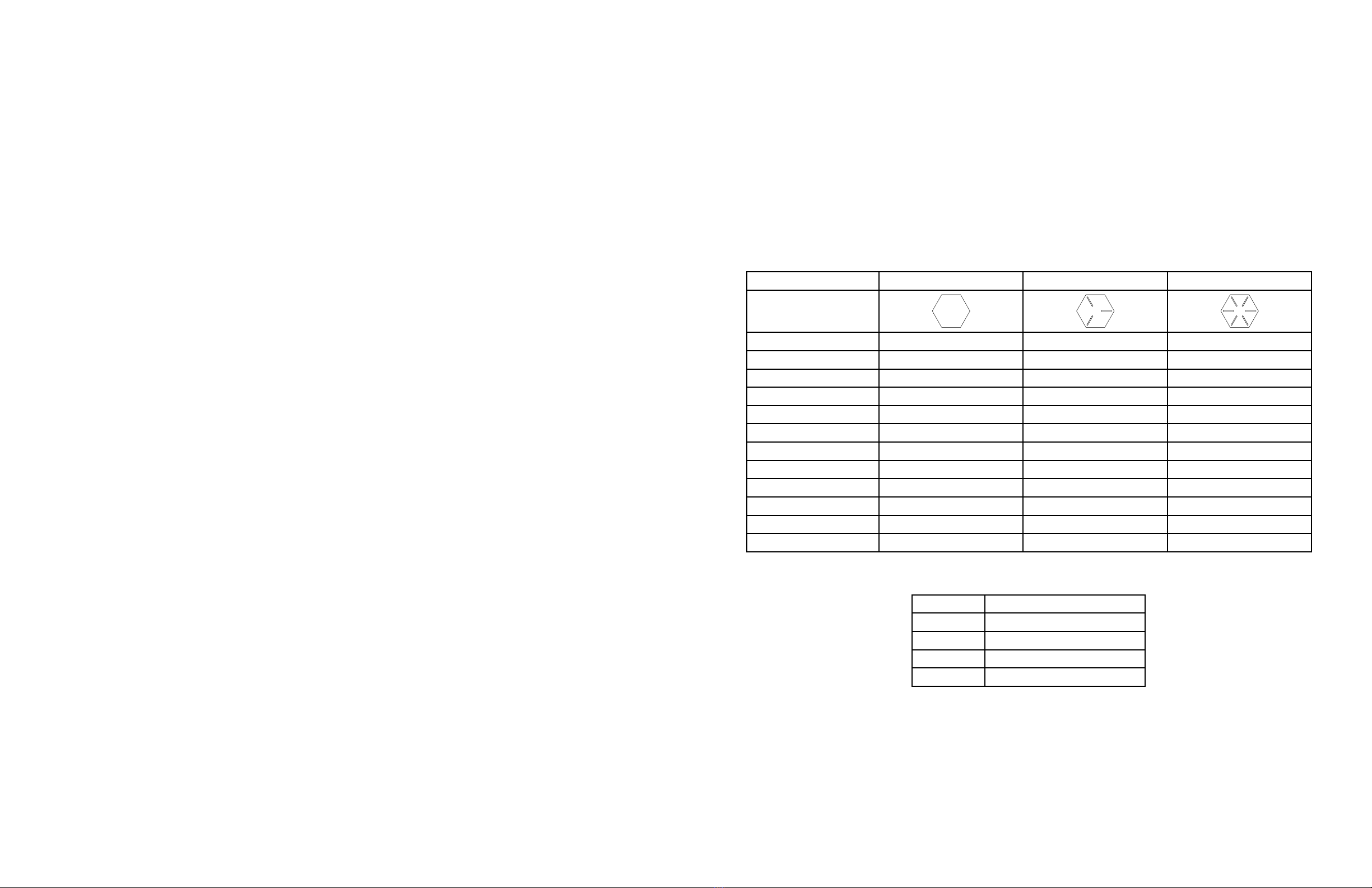
Find the “D” dimension in TABLE 1, on page 6, for the hoist model and desired dump angle. Using this
dimension, measure forward from the center of the rear hinge and mark the truck frame. Place the hoist on
the truck frame. (See Fig. 2) Center the front cross tube of the hoist over the mark on the truck frame. Be
sure to allow enough room for the cylinders to swing as the body is raised. Make sure the hoist is centered
onandsquarewiththetruckframe.Theanglemountingbracketsmustrestatonthetruckframe.Ifriv-
ets are encountered in the truck frame, and the hoist cannot be moved to clear them, countersink the rivet
heads into the brackets. The rear end of the main hoist frame is designed to rest on a crossmember in the
truck frame. If no crossmember exists to support the hoist frame, add one.
Note:Insomecasesthehoistmaytthetruckframebetterifitismountedreversedor“backwards”as
shown in Figure 3. When mounting the hoist “backwards” be sure to measure to the front crosstube of the
hoist as shown in Figure 3 and to allow enough room for the cylinders to swing as the body is raised.
be opened slightly to do this.) Check the cylinder
mounting screws, they should be tight.
NOTE: NO CROSSBRACING allowed within cylinder swing clearance area. Crossbracing will lead to
interference with the working operation of the hoist. ( Fig. 2 and 3 on the Tandem Axle Trucks.)
tion. Securely weld the gussets to the rear hinge,
thetruckframerailandthetopangeofthetruck
frame rail.
LOCATEHOISTONTRUCKFRAME
D"
33"
TANDEM AXLE TRUCKS
SINGLE AXLE TRUCKS
STANDARD HOIST MOUNTING
D"
45"
RIVETSTRIPS
12" MAXIMUM
CYLINDER SWING
CLEARANCE NEEDED
STANDARD HOIST MOUNTING
FIG. 2

1643043B (401509) 2020-SEPT-2481643043B (401509) 2020-SEPT-249
MOUNTHOISTTOTRUCKFRAME
Center the mounting angles under the angle mount-
ing brackets on the hoist. Clamp them in place and
mark the truck frame for drilling, using the mount-
ing angles as guides. (See Fig. 4)
MODEL
DUMP ANGLE
40º 45º 50º 55º
1900 113” 97” 88” 81”
4400 136” 123” 111” 102”
5500 171” 153” 140” 128”
6600 191” 171” 156” 143”
7700 208” 186” 169” 155”
TABLE1
CAUTION:WHEN DRILLING THE
TRUCK FRAME BE CAREFUL
OF BRAKELINES, WIRING, ETC,
INSIDE THE TRUCK FRAME.
Drill 21/32 inch holes in the truck frame and bolt
the mounting angles in place using 5/8 x 1 3/4 cap
screws, lock washers and hex nuts. Securely weld
the angle mounting brackets to the mounting an-
gles.
MOUNTGEARPUMP
ThegearpumphasanSAE`B’mountingconguration,a13-toothsplinedshaftandafour-boltmount-
ingange,andisassembledforrotationineitherdirection.NOTE:Thispumpwillmountdirectlyto
Chelsea’soutputtype`XK’orMuncie’soutputtype`D’.CrysteelManufacturingrecommendsaPTOratio
of 100-120%. This assures a minimum pump operating speed of 600 RPM. Bolt the gear pump to the PTO
outputangeusing1/2x11/4”capscrewsandlockwashers.
MOUNTRESERVOIR/VALVEASSEMBLY
The reservoir/valve assembly should be mounted on the same side of the truck as the pump with the ex-
posed end of the valve spool toward the front. Bolt the mounting angles to the reservoir/valve assembly
using3/8x 1capscrews,atwashers, lockwashersandhex nuts.Placethevalve/reservoir assembly
inside the truck frame and raise it as high as possible. See Fig. 5. (There is no drive line to align and the
reservoir should be higher than the pump for reliable performance.) Make sure there is enough clear-
ance for the truck drive line and hot exhaust pipes. THE ENGINE EXHAUST MUST NEVER BLOW
DIRECTLY ONTO THE RESERVOIR/VALVE ASSEMBLY. Clamp the mounting angles to the truck
frame and mark the truck frame for drilling using the pump mounting angles as guides.

1643043B (401509) 2020-SEPT-2410 1643043B (401509) 2020-SEPT-2411
INSTALLREMOTEVALVECONTROL
CAUTION: WHEN DRILLING THE TRUCK FRAME BE CAREFUL OF
BRAKELINES, WIRING, ETC. INSIDE THE TRUCK FRAME.
Drill 17/32” holes in the truck frame and bolt the reservoir/valve assembly in place using 1/2 x 1 3/4” cap
screws, lock washers and hex nuts.
Temporarily assemble the valve control head to the pedestal using 5/16 x 2 1/4” machine screws and hex
nuts.Placethisassemblyontheoorofthecab.Makesurethereisenoughroomtooperatethevalvecon-
trolandthegearshiftleverandtoadjusttheseat.Checkbelowtheoorforobstructionsandcablerouting.
Relocatethevalvecontrolifnecessary.Marktheoorusingthepedestalasatemplateanddrill1/4”holes
for the mounting screws and a 3/4” hole for the control cable. Assemble the control cable to the valve
control head and assemble the valve control head and cover to the pedestal using 5/16 x 2 1/4” machine
screws,lockwashersandhexnuts.Insertthecontrolcablethroughtheholeintheoorandmountthe
pedestaltotheoorusing5/16x3/4”self-tappingscrews.Makesurethevalvecontrolleverisinitscenter
detentposition.Keepthecontrolcableawayfromhotexhaustpipesandrotatingdriveshafts.Thecontrol
cable should not have any sharp bends or kinks in it (these will make the control harder to operate).
Install the 3/4” hex jam nut onto the valve end of the control cable and turn past the threads. Insert the end
of the cable through the bonnet clamp. Install the bonnet onto the control cable and turn it past the threads
also. Install the 1/4” hex jam nut and terminal eye on the core rod of the cable. Lock the terminal eye to
the core rod using the hex jam nut. Place the terminal eye in the slot of the valve spool; insert the short pin
through the valve spool and terminal eye and secure it in place with the cotter pin.
Threadthebonnetontotheendofthecablesoitrmlytouchestheendvalve.(Donotoverorunder
tighten the bonnet as either would move the valve spool out of its neutral position.) Remove two cap
screws from opposite corners of the seal retainer plate. Slide the bonnet clamp onto the bonnet and secure
ittothevalveusingthe1/4x11/4”capscrews,lockwashersandatwashers.Lockthebonnettothe
cable using the 3/4” hex jam nut. See Fig. 6.
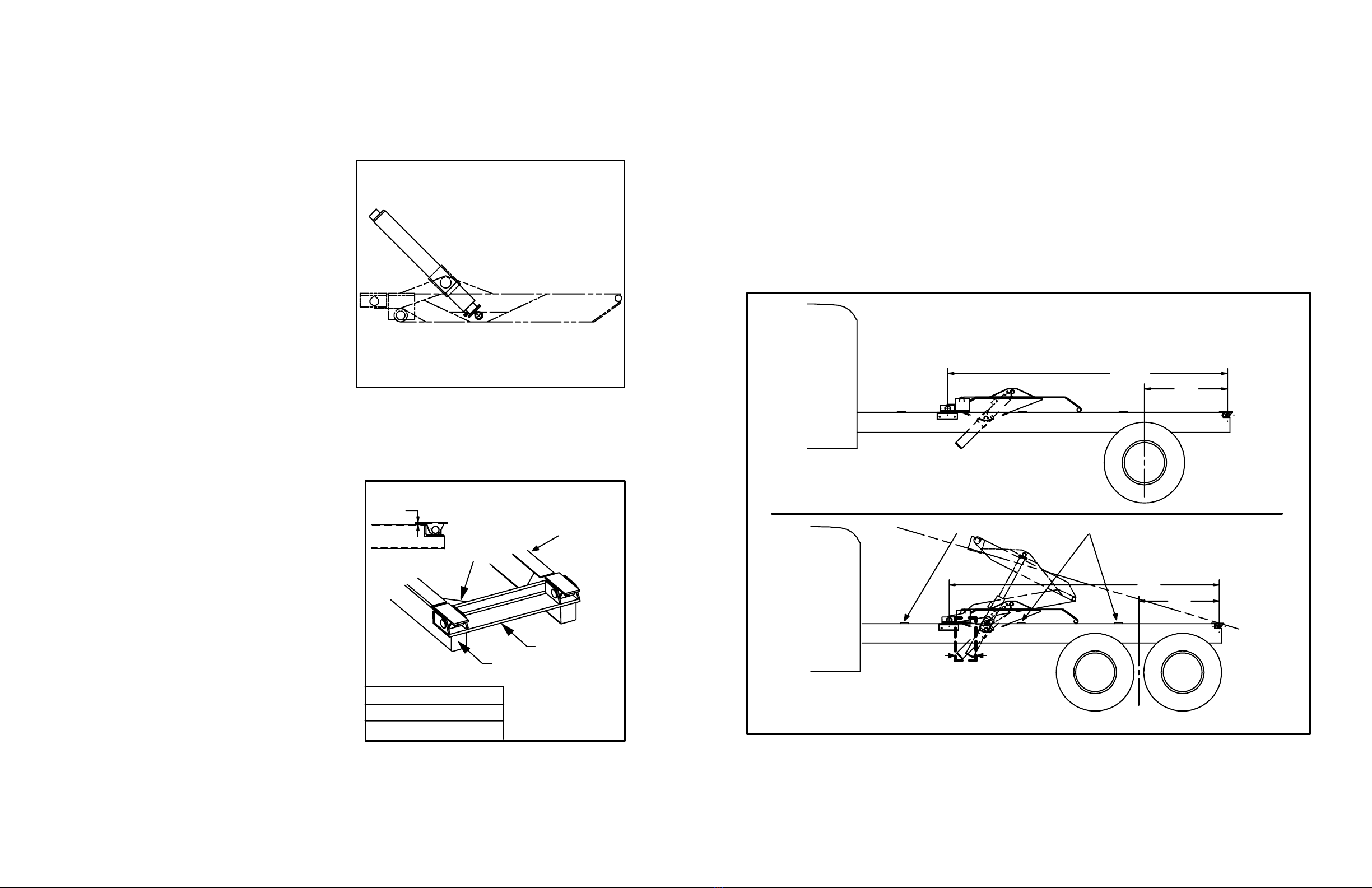
INSTALLHOSES-1900
Study Fig. 7 very carefully before connecting the hoses. Install a 3/4’’ 90° street elbow and a 3/4” hose
barb in the suction port on the bottom of the reservoir. Install a 1 1/16 ORB x 3/4” hose barb in the suction
port on the pump and install the suction hose. Secure the suction hose in place using hose clamps. Install
a 1 1/16 ORB x 7/8 ORB adapter in the pressure port of the pump and install a 90° swivel adapter in the
`IN’ port on the control valve. Install the 72” long 1/2” hose from the pump to the valve.
Install 90° swivel adapters in the work ports of the control valve and the ports on the base end of the cyl-
inders; install straight swivel adapters in the ports on the rod end of the cylinders. Connect 18” long 3/8”
hoses from the rod end ports of the cylinders to a swivel nut tee; connect a 60” long 3/8” hose from this tee
to the ‘A’ port on the control valve. Connect 18” long 3/8” hoses from the base end ports of the cylinders
to a swivel nut tee; connect a 60” long 3/8” hose from this tee to the ‘B’ port on the control valve. This
will raise the hoist when the control lever is pulled back and lower it when pushed forward. Secure the 18”
long hoses to the cylinder mount using the tie straps provided.
NOTE: The `A’ port is the `power-down’ port and has a pressure of only 500-1000 PSI at engine idle; the
`B’ port has full system pressure.
Study Fig. 8 very carefully before connecting the hoses. Install a 1 1/4’’ 90° street elbow and a 1 1/4”
hose barb in the suction port on the bottom of the reservoir. Install a 1 5/16 ORB x 1 1/4” hose barb in the
suction port on the pump and install the suction hose. Secure the suction hose in place using hose clamps.
Install a 1 5/16 ORB x 1/2 NPT adapter in the pressure port of the pump and install a 90° swivel adapter
in the `IN’ port on the control valve. Install the 72” long 1/2” hose from the pump to the valve.
Install 90° swivel adapters in the ‘B’ work port of the control valve and the ports on the base end of the
cylinders. Connect a 60” long 1/2” hose from the control valve to the swivel nut tee; connect 24” long 1/2”
hoseS from the tee to the ports on the base end of the cylinder. This will raise the hoist when the control
lever is pulled back and lower it when pushed forward. Secure the 24” long hoses to the cylinder mount
using the tie straps provided.
INSTALL HOSES - 4400 SINGLE-ACTING
COTTER PIN
1643043B (401509) 2020-SEPT-2412 1643043B (401509) 2020-SEPT-2413
INSTALL HOSES - 5500, 6600 & 7700 SINGLE-ACTING
Study Fig. 8 very carefully before connecting the hoses. Install a 1 1/2” 90° street elbow and an 1 1/2”
hose barb in the suction port on the bottom of the reservoir. Install a 1 5/16 ORB x 1 1/2” hose barb in the
suction port of the pump and install the suction hose. Secure the suction hose in place using hose clamps.
Install a 1 5/16 ORB x 3/4” NPT adapter in the pressure port of the pump and install a 90° swivel adapter
in the “IN” port of the control valve. Install the 72” long 3/4” hose from the pump to the valve.
Install 90° swivel adapters in the ‘B’ work port of the control valve and the ports on the base end of the
cylinders. Install a 7/8 ORB x 3/4” NPT swivel in the middle port of the 7/8 ORB tee.
Connect a 60” long 3/4” hose from the ‘B’ port of the control valve to the middle port of the tee; connect
24” long 1/2 NPT-7/8 ORB hoses (30” long hoses for the 6600) from the tee to the ports on the base end
of the cylinders. This will raise the hoist when the control lever is pulled back and lower it when pushed
forward. Secure the 24” (30”) long hoses to the cylinder mount using the tie straps provided.
INSTALL HOSES - 4400 DOUBLE-ACTING
Study Fig. 9 very carefully before connecting the hoses. Install a 1 1/4” 90° street elbow and a 1 1/4” hose
barb in the suction port on the bottom of the reservoir. Install a 1 5/16 ORB x 1 1/4” hose barb in the suc-
tion port on the pump and install the suction hose. Secure the suction hose in place using hose clamps.
Install a 1 5/16 ORB x 1/2 NPT adapter in the pressure port of the pump and install a 90° swivel adapter
in the `IN’ port of the control valve. Install the 72” long 1/2” hose from the pump to the valve.
Install 90° swivel adapters in the work ports of the control valve and the ports on the base end of the cyl-
inders. Connect a 60” long 1/2” hose from the ‘B’ port of the control valve to the swivel nut tee; connect
24” long 1/2” hose from the tee to the ports on the base end of the cylinder. Secure the 24” long hoses to
the cylinder mount using the tie straps provided.
There is plumbing inside the hoist frame for the power down function of the hoist. Install a 3/8 NPT x 1/2
NPT swivel adapter in the pipe elbow near the front of the hoist frame. Connect a 42” long 1/2” hose from
the`A’portonthecontrolvalvetotheswiveladapter.Connect27”long1/4”hosesfromthepipettings
on the upper frame to the ports on the rod end of the cylinders. This will raise the hoist when the control
lever is pulled back and lower it when pushed forward.
NOTE: Only the smallest stage is double acting.
NOTE: The `A’ port is the `power-down’ port and has a pressure of only 500-1000 PSI at engine idle; the
`B’ port has full system pressure.
INSTALL HOSES - 5500, 6600 & 7700 DOUBLE-ACTING
Study Fig. 9 very carefully before connecting the hoses. Install a 1 1/2” 90° street elbow and an 1 1/2”
hose barb in the suction port on the bottom of the reservoir. Install a 1 5/16 ORB x 1 1/2” hose barb in the
suction port of the pump and install the suction hose. Secure the suction hose in place using hose clamps.
Install a 1 5/16 ORB x 3/4 NPT adapter in the pressure port of the pump and install a 90° swivel adapter
in the `IN’ port of the control valve. Install the 72” long 3/4” hose from the pump to the valve.
Install 90° swivel adapters in the work ports of the control valve and the ports on the base end of the cyl-
inders. Install a 7/8 ORB x 3/4 NPT swivel in the middle port of the 7/8 ORB tee. Connect a 60” long 3/4”
hose from the ‘B’ port of the control valve to the middle port of the tee; connect 24” long 1/2 “ hoses (30”
long hoses for the 6600) from the tee to the ports on the base end of the cylinders. Secure the 24” (30”)
long hoses to the cylinder mount using the tie straps provided.
There is plumbing inside the hoist frame for the power down function of the hoist. Install a 3/8 NPT x 1/2
NPT swivel adapter in the pipe elbow near the front of the hoist frame. Connect a 42” long 1/2” hose from
the`A’portonthecontrolvalvetotheswiveladapter.Connect27”long1/4”hosesfromthepipettings
on the upper frame to the ports on the rod end of the cylinders. This will raise the hoist when the control
lever is pulled back and lower it when pushed forward.
NOTE: Only the smallest stage is double acting.
NOTE: The `A’ port is the `power-down’ port and has a pressure of only 500-1000 PSI at engine idle; the
`B’ port has full system pressure.

1643043B (401509) 2020-SEPT-2414 1643043B (401509) 2020-SEPT-2415
ADDHYDRAULICOIL
RefertoTABLE2belowfortheamountofhydraulicoilrequiredtooperatethehoist.Useaqualityhy-
draulicuidof150SSU@100_F.whichcontainscorrosionandoxidationinhibitorsandafoamdepres-
sant.ThisisapproximatelytheequivalentofSAE10Worlighterweightoil,oruseTypeAautomatic
transmissionuidforimprovedperformanceincoldweather.
HOIST
MODEL
RESERVOIR
SIZE
OIL
REQUIRED
1900 6 GAL. 15 QTS
4400 8 GAL. 27 QTS
5500 14 GAL. 34 QTS
6600 14 GAL. 39 QTS
7700 14 GAL. 42 QTS
TABLE2
MOUNT BODY
It is recommended that the body be painted before it is mounted on the truck. Place the body in position
on the truck with three inches of clearance behind the cab. Use the rivet strip mounting pads between the
longbeams and the truck frame. Use three on each side, spaced as seen on Fig. 2 on page 5 or Fig. 3 on
page 6. Weld them to the longbeams. Align body longbeams carefully with the truck frame. Securely weld
the longbeams to the rear hinge brackets.
Weldthelongbeamstotheangleliftbracketsofthehoist.Ontheinsideofthelongbeams,inserttheller
platebetweentheliftbracketandthelongbeam.Securelyweldthellerplatetotheangleliftbracketsand
tothetopangeofthelongbeamchannelsasshowninFig.10.ForCrysteel’sgrainbody,placetheller
plate between the angle lift bracket and the inside of the longbeam as shown in Fig. 11. Securely weld this
plate to the longbeam and to the lift bracket. Be sure to do this on both sides.
INSTALLBODYGUIDES
The four body guides supplied with your hoist are of two types. Part number 217503 has an obtuse angle
that allows it to match the angle of fabricated longbeams. Position this type as shown in Fig. 12 with wide
end down, pushed against the longbeam, and centered over the hoist lower mounting angle. Weld securely
to the mounting angles. DO NOT use the other body guides with fabricated longbeams.
Part number 201415 body guide is used with channel type longbeams and has a right angle that allows it
to be positioned as shown in Fig. 13. Position this guide 1/4” away from the longbeam, centered over the
lowermountingangle.Placethe217503bodyguideinsideofitasshownsothattheatsidesoftheguides
ttogether.Weldnumber201415tothelowermountingangleand217503tothelongbeam.
There should be NO SIDEPLAY when the truck body is in the lowered position.
Fig. 12 Fig. 13
FABRICATED
LONGBEAM
217503
MOUNTING
ANGLE
LONGBEAM
CHANNEL
201415
217503
MOUNTING
ANGLE
INSTALL BODY PROP
The body prop is designed and intended to support an EMPTY truck body in the raised position. Use of the
body prop permits service to be performed safely beneath a raised body. One body prop is included with
Stingray Hoist models 1900; two body props (one pair) are included with models 4400 through 7700. Be
sure to install each prop on the correct side of the truck as explained below. (See Fig. 14)
1. Raise the body to a 30º to 35º angle and brace it securely before beginning installation.
2. Assemble the prop arm to the prop pivot mount with a 1/4 x 3 roll pin. Clamp the prop pivot
mount against the outside of the truck frame just behind the rear axle. Raise the body prop arm to
a free standing position. Place the body prop bracket in the prop arm saddle. Reposition if needed
to locate the prop bracket on the longbeam. It may be necessary to raise or lower the body to get
the best location for the prop pivot mount. Using the prop pivot mount as a guide, mark the loca-
tion of holes on the truck frame and drill 17/32 inch holes. Assemble the prop pivot mount to the
frame using 1/2 x 2 cap screws, lock washers and hex nuts. Raise the prop arm to a free standing
position, place the body prop bracket in the saddle and securely weld the bracket to the long-
beam.
3. When mounting two body props, repeat steps 1 and 2 for the other side. Use the body prop al-
ready mounted to assure that both body props hold the body at the same height. The left and right
body props should pivot toward the front of the truck in the storage position.

1643043B (401509) 2020-SEPT-2416 1643043B (401509) 2020-SEPT-2417
BLEED CYLINDERS - SINGLE ACTING
TheStingRaysingle-actingcylindersareequippedwithaself-bleedingfeature.Whenrstinstalled,raise
the body to full height and lower completely two or three times. Air is removed from the cylinder every
timethehoistiscycled.Nofurtherbleedingisrequired.
NOTE: Double-acting cylinders do not have bleed valves because they bleed themselves in use. Cycle
the hoist several times to remove any air from the cylinders
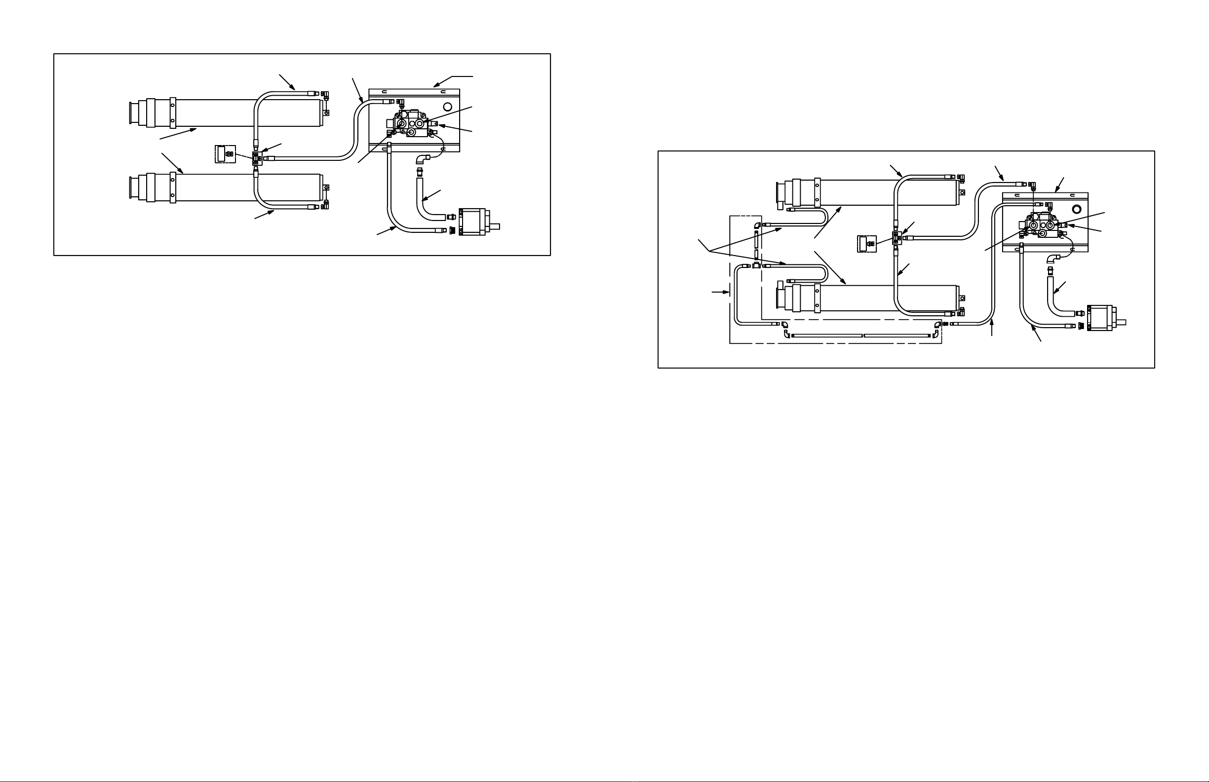
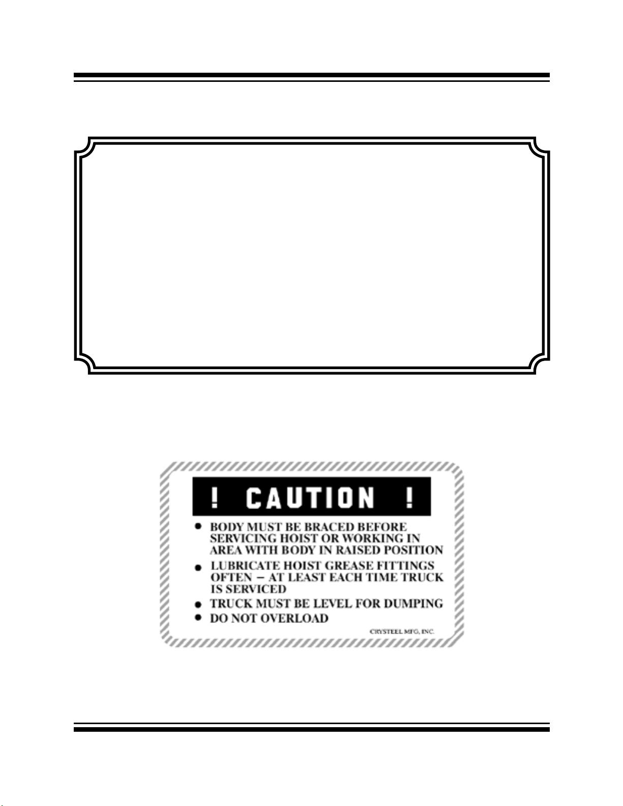
INSTALLDECALS
After the body and hoist have been installed and painted, install the decals in the following locations:
1. Decal 1642848 Mount on the body longbeam near the body prop. (one on each side)
2. Decal 1642846 Mount on the body prop arm.
3. Decal 1643067 Mount on the outside of the body longbeams near the front of the body.
(one on each side).
4. Decal 1642844 Mount on the body longbeam on the drivers side.
5. Decal 1643068 Mount in the cab in a prominent location.
6. Decal 1642843 Mount in the cab in a prominent location.
Seetheillustrationsonthefollowingpagefordecalidentication.(SeeFig.15.)
4. Tooperatethebodyprop,raisethebodytothedesiredheight,shutoallpower,raisetheprop
arm to a free standing position. Lower the body slowly until the body prop bracket contacts the
prop arm saddle. DO NOT POWER HOIST DOWN.
5. To place the body prop in the storage position, raise the body to clear the body prop saddle,
lower the body prop to the storage position and lower the body.
Install grease zerks and lubricate in the following locations:
A. UpperCrosstube 2ttings
B. LowerCrosstube 2ttings
C. BodyProps 2ttings
D. RearHinge 2ttings(Installed)
Lubricateallttingsatregularintervals,atleastevery100cyclesor2months.Thereareveryhighforces
on the bearing surfaces within the hoist frame. It pays to be generous in lubricating the hoist to ensure
proper operation and long life.
GREASE HOIST
PROPER LUBRICATION IS EXTREMELY IMPORTANT!
The center hinge, the cylinder crossheads and the lower cylinder mount do not need to be greased. These
pivotpointsareequippedwithselflubricatingcompositebearingsthatdonotneedlubrication.
ONE OF THE MOST COMMON REASONS FOR HOIST PROBLEMS IS
FAILURE BY THE OPERATOR TO LUBRICATE THE HOIST.
1643043B (401509) 2020-SEPT-2418 1643043B (401509) 2020-SEPT-2419
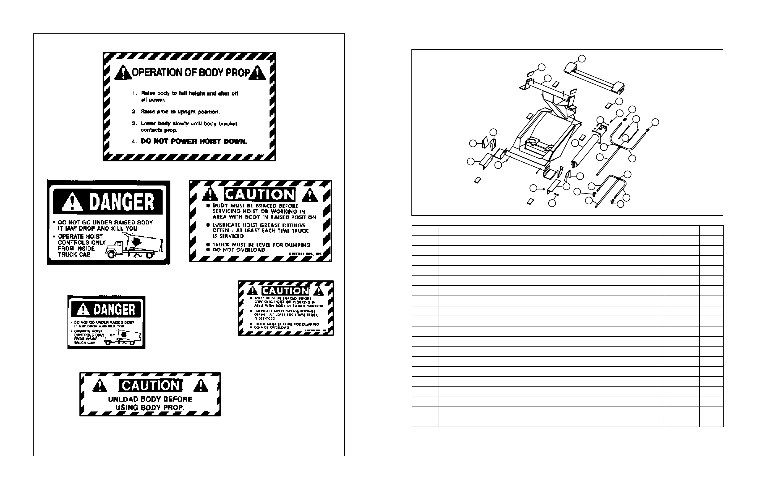
ITEM DESCRIPTION SR1900 QTY
1. Body Guide 1629456 2
1a. Body Guide 1630513 2
2. Mounting Angle 1629458 2
3. Grease Zerk 1/8 NPT, Straight 1645187 6
4. Hex Lock Nut 5/8-11 1643070 4
5. Hex Cap Screw 5/8-11 x 2 1643313 4
6. Longbeam Filler 1629382 2
7. Hoist Frame 1621823 1
8. Rear Hinge 1621587 1
9. Longbeam Spacer 1629377 6
10. Cylinder 1621794 2
11. Hex Lock Nut 3/8-16 1643177 8
12. Hex Cap Screw 3/8-16 x 1 1/2 1642710 8
13. Hose 3/8 NPT x 60 1643348 2
14. Hose 3/8 NPT x 18 1643347 4
15. Swivel Tee 3/8 NPSM 1643235 2
16. Tie Strap 1643056 2
17. Adapter 9/16 ORBM X 3/8 NPSM 90° 1643239 2
18. Adapter 9/16 ORBM X 3/8 NPSM 1643238 1
Fig. 15
FIG. 15
1642848
1642844
1642843
1643067
1643068
1642846
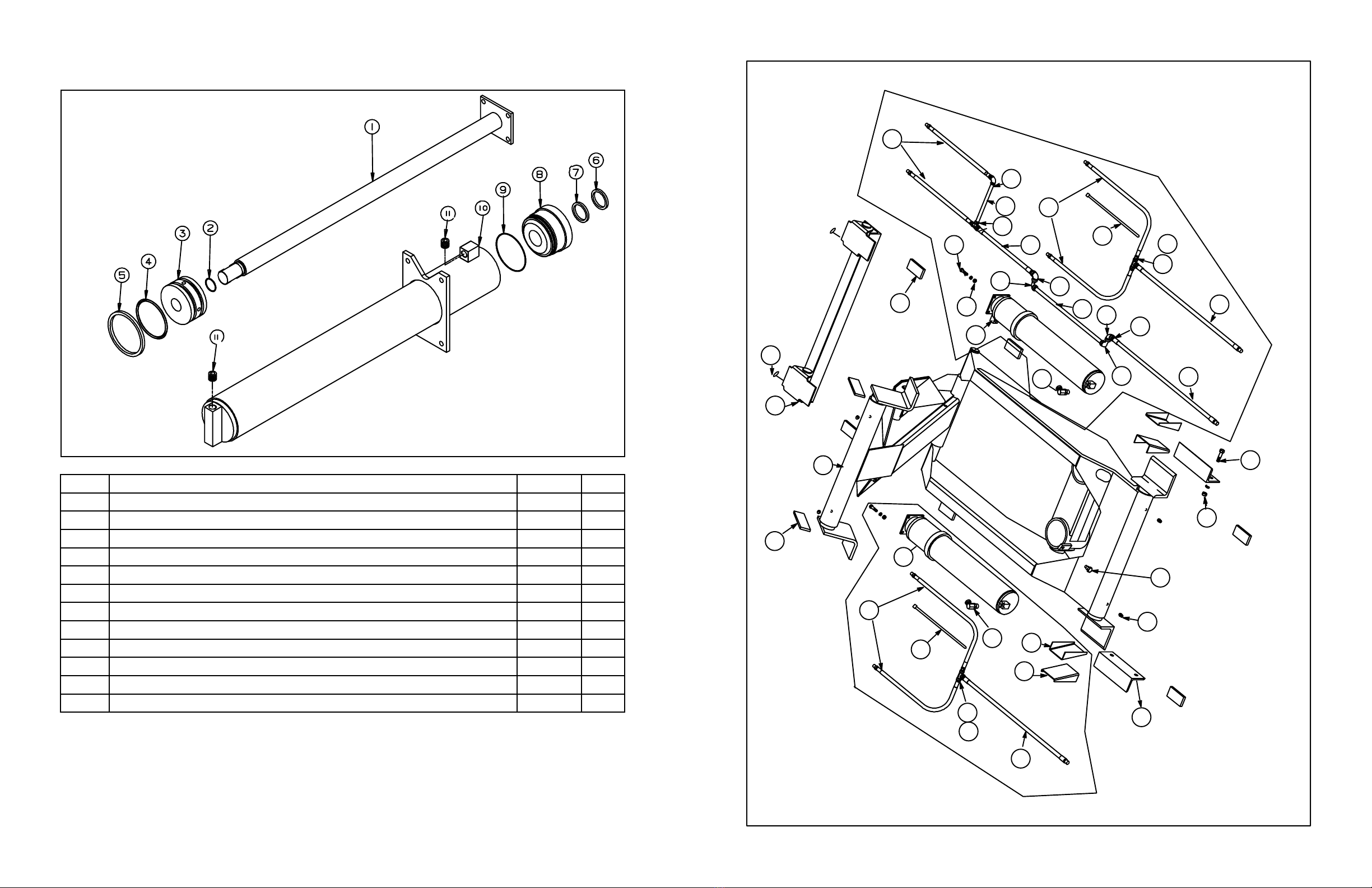
SR1900
HOIST FRAME
STINGRAY1900HOISTPARTS
1643043B (401509) 2020-SEPT-2420 1643043B (401509) 2020-SEPT-2421
STINGRAY1900CYLINDERPARTS
ITEM DESCRIPTION SR1900 QTY
1. Shaft Assy 1621812 1
2. O-Ring * 1642940 1
3. Piston 1630418 1
4. O-Ring * 1643080 1
5. Poly Seal * 1643092 1
6. Wiper 1643081 1
7. Poly Seal * 1642941 1
8. Head 1630417 1
9. O-Ring * 1642890 1
10. Outer Tube Assy 1621796 1
11. Plug 9/16 ORB 1642793 1
12. SealKit 1621831 1
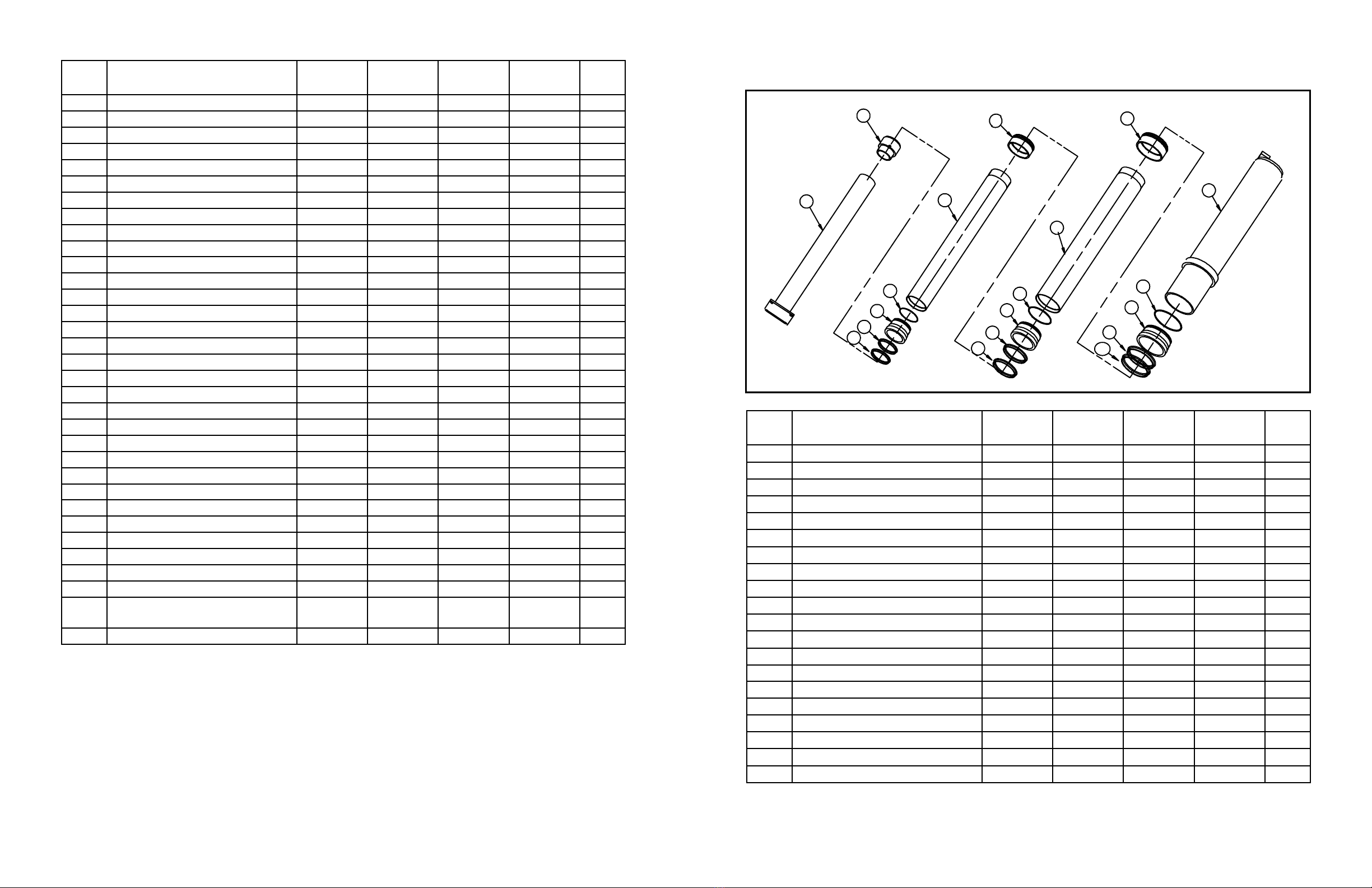
4400 THRU 7700
SINGLE
ACTING
DOUBLE
ACTING
1643043B (401509) 2020-SEPT-2422 1643043B (401509) 2020-SEPT-2423
ITEM DESCRIPTION MODEL
4400
MODEL
5500
MODEL
6600
MODEL
7700
QTY.
1. Hose 1/2 NPT 1643225 1643154 1643154 1643154 1
2. Tee 1/2 NPSM Swivel 1643242 1
Tee 7/8 ORB 1629343 1629343 1629343 1
2a. Swivel 7/8 ORBM x 3/4 NPTF 1643192 1643192 1643192 1
3. Hose 1/2 NPT 1643243 1642979 1643237 1642979 2
4. Cylinder - SA 1622309 1622310 1622311 1622312 2
5. Body Guide 1629456 1629456 1629456 1629456 2
6. Body Guide 1630513 1630513 1630513 1630513 2
7. Mounting Angle 1629458 1629458 1629458 1629458 2
8. Grease Zerk 1645187 1645187 1645187 1645187 6
9. Retaining Screw 1643079 1643079 1643079 1643079 2
10. Hex Lock Nut 5/8-11 1643070 1643070 1643070 1643070 4
11. Hex Cap Screw 5/8-11 x 2 1643313 1643313 1643313 1643313 4
12. Longbeam Filler 1629379 1629379 1629379 1629379 2
13. Hoist Frame - SA 1621713 1621693 1621723 1621732 1
Hoist Frame - DA 1621782 1621783 1621784 1621785 1
14. Rear Hinge 1283750 1283750 1283750 1283750 1
15. Longbeam Spacer 1629376 1629376 1629376 1629376 6
16. Cylinder - DA 1621768 1621769 1621770 1621771 1
17. Hex Lock Nut 3/8-16 1643177 1643177 1643177 1643177 8
18. Hex Cap Screw 3/8-16 x 1 1/2 1642710 1642710 1642710 1642710 8
19. Hose 1/2 NPT x 42 1643223 1643223 1643223 1643223 1
20. Street Elbow 3/8 Pipe 1642796 1642796 1642796 1642796 2
21. Elbow 3/8 Pipe 1642797 1642797 1642797 1642797 2
22. Pipe 3/8 1643050 1643072 1643073 1643074 1
23. Hose 3/8 NPT 1642821 1642823 1642824 1642825 1
24. Tee Reducing 3/8 x 1/4 x 1/4 1643048 1643048 1643048 1643048 1
25. Pipe 1/4 x 9 1643049 1643049 1643049 1643049 1
26. Elbow 1/4 Pipe 1642801 1642801 1642801 1642801 1
27. Hose 1/4 NPT x 27 1643284 1643284 1643284 1643284 1
28. Tie Strap 1643056 1643056 1643056 1643056 3
29.
Adapter 7/8 ORBM x 1/2 NPTF
90° 1642927 1642927 1642927 1642927 2
30. Swivel 3/8 NPTM x 1/2 NPTF 1643232 1643232 1643232 1643232 1
ITEM DESCRIPTION MODEL
4400
MODEL
5500
MODEL
6600
MODEL
7700
QTY.
1. Inner Tube Assy 1622604 1622711 1622712 1622713 1
2. Inner Piston 1630331 1630330 1630330 1630330 1
3. Wiper 2 3/4 ID * --- 1643380 1643380 1643380 1
4. Seal 2 3/4 ID x 1/4 * --- 1643107 1643107 1643107 1
5. Head 2 3/4 ID --- 1632755 1632755 1632755 1
6. O-Ring 2 7/8 ID x .070 * --- 1642889 1642889 1642889 1
7. Stage Tube 3 1/2 OD --- 1632492 1632493 1632494 1
8. Piston 3 1/2” Stage --- 1629926 1629926 1629926 1
9. Wiper 3 1/2 ID * 1643366 1643366 1643366 1643366 1
10. Seal 3 1/2 ID x 1/4 1643108 1643108 1643108 1643108 1
11. Head 3 1/2 ID 1632507 1632507 1632507 1632507 1
12. O-Ring 3 1/2 ID x .070 1642890 1642890 1642890 1642890 1
13. Stage Tube 4 1/4 OD 1632761 1632762 1632763 1632764 1
14. Piston 4 1/4” Stage 1629927 1629927 1629927 1629927 1
15. Wiper 4 1/4 ID * 1643367 1643367 1643367 1643367 1
16. Seal 4 1/4 ID x 1/4 * 1643109 1643109 1643109 1643109 1
17. Head 4 1/4 ID 1632756 1632756 1632756 1632756 1
18. O-Ring 4 1/4 ID x .070 * 1642891 1642891 1642891 1642891 1
19. Outer Tube Assy 1622791 1622602 1622792 1622793 1
20. SealKit(Includes*items) 1621862 1621863 1621863 1621863 1
STINGRAY4400-7700SACYLINDERPARTS

1643043B (401509) 2020-SEPT-2424 1643043B (401509) 2020-SEPT-2425
FIG. 20
1
3
4
5
62
7
8
9
10
11
12
13
14
15
16
17
18
19
20
21
22
23
DOUBLE ACTING HOIST
24
ITEM DESCRIPTION MODEL
4400
MODEL
5500
MODEL
6600
MODEL
7700
QTY.
1. Inner Tube Assy 1622603 1622707 1622708 1622709 1
2. Inner Piston 1630550 1630549 1630549 1630549 1
3. Ball 3/8 Dia 1642679 1642679 1642679 1642679 1
4. O-Ring 7/16 ID x .070 1642907 1642907 1642907 1642907 1
5. Body, Bypass Valve 1642893 1642893 1642893 1642893 1
6. Pin, Bypass Valve 1642992 1642992 1642992 1642992 1
7. Seal, PIP 3” OD * --- 1643132 1643132 1643132 1
Seal, PIP 3 3/4” OD * 1643133 --- --- --- 1
8. Wiper 2 3/4 ID * --- 1643380 1643380 1643380 1
9. Seal 2 3/4 ID x 1/4 * --- 1643107 1643107 1643107 1
10. Head 2 3/4 ID --- 1632755 1632755 1632755 1
11. O-Ring 2 7/8 ID x .070 * --- 1642889 1642889 1642889 1
12. Stage Tube 3 1/2 OD --- 1630546 1630547 1630548 1
13. Piston 3 1/2” Stage --- 1629926 1629926 1629926 1
14. Wiper 3 1/2 ID * 1643366 1643366 1643366 1643366 1
15. Seal 3 1/2 ID x 1/4 1643108 1643108 1643108 1643108 1
16. Head 3 1/2 ID 1632507 1632507 1632507 1632507 1
17. O-Ring 3 1/2 ID x .070 1642890 1642890 1642890 1642890 1
18. Stage Tube 4 1/4 OD 1632773 1632762 1632763 1632764 1
19. Piston 4 1/4” Stage 1629927 1629927 1629927 1629927 1
20. Wiper 4 1/4 ID * 1643367 1643367 1643367 1643367 1
21. Seal 4 1/4 ID x 1/4 * 1643109 1643109 1643109 1643109 1
STINGRAY4400-7700DACYLINDERPARTS ITEM DESCRIPTION MODEL
4400
MODEL
5500
MODEL
6600
MODEL
7700
QTY.
22. Head 4 1/4 ID 1632756 1632756 1632756 1632756 1
23. O-Ring 4 1/4 ID x .070 * 1642891 1642891 1642891 1642891 1
24. Outer Tube Assy 1621838 1621839 1621840 1621841 1
25. SealKit(Includes*items) 1621866 1621867 1621867 1621867 1
STINGRAY HYDRAULICS
ITEM DESCRIPTION MODEL
1900
MODEL
4400
MODELS
5500 6600
7700
QTY.
1. Mounting Angle Assy 1621472 1621472 1621472 2
2. Hex Lock Nut 1/2-13 1642984 1642984 1642984 4
3. Hex Cap Screw 1/2-13 x 2 1642701 1642701 1642701 4
4. Hex Cap Screw 3/8-16 x 1 1642714 1642714 1642714 4
5. Flat Washer 3/8 1642732 1642732 1642732 4
6. Hex Lock Nut 3/8-16 1643177 1643177 1643177 4
7. Breather Cap 1644723 1644723 1644723 1
8. Reservoir - 6 Gallon 1621925 --- --- 1
Reservoir - 8 Gallon --- 1621921 --- 1
Reservoir - 14 Gallon --- --- 1621923 1

1643043B (401509) 2020-SEPT-2426 1643043B (401509) 2020-SEPT-2427
ITEM DESCRIPTION MODEL
1900
MODEL
4400
MODELS
5500 6600
7700
QTY.
9. Valve - DA 4000 PSI 7/8 ORB Ports 1643187 --- --- 1
Valve - DA 3250 PSI 7/8 ORB Ports --- 1643185 1
Valve - SA 3250 PSI 1 1/16 ORB Ports --- 1643188 1643188 1
Valve - DA 3250 PSI 1 1/16 ORB Ports --- 1643200 1
10. O-Ring 0.924 ID x .116 1642922 1642922 1642922 1
11. Soc Cap Screw 5/16-18 x 2 1643205 1643205 1643205 1
12. ConnectionKit-RVC 1643215 1643215 1643215 1
13. Adapter 7/8 ORBM x 3/8 NPTF 90° 1642954 2
Adapter 7/8 ORBM x 1/2 NPTF 90° 1642927 DA 2
SA 1
Adapter 1 1/16 ORBM x 1/2 NPTF 90° 1642969 DA 2
SA 1
Adapter 1 1/16 ORBM x 3/4 NPTF 90° 1642971 DA 2
SA 1
14. Adapter 1 1/16 ORBM x 1/2 NPTF 90° 1642969 1642969 1
Adapter 1 1/16 ORBM x 3/4 NPTF 90° 1642971 1
15. Pipe Plug 3/4” Magnetic 1642794 1642794 1642794 1
16. Pipe Elbow 3/4” Street 90° 1643226 1
Pipe Elbow 1 1/4” Street 90° 1642975 1
Pipe Elbow 1 1/2” Street 90° 1643227 1
16a. Hex Bushing 1 1/2 NPT x 1 1/4 NPT 1643230 1
17. Hose Barb 3/4 NPT x 3/4 1643017 1
Hose Barb 1 1/4 NPT x 1 1/4 1643018 1643018 1
18. Hose Clamp #24 1643011 2
Hose Clamp 1 3/4 T-Bolt 1643241 1643241 2
19. Suction Hose 3/4” ID x 6’ 1643805 1
Suction Hose 1 1/4” ID x 6’ 1643806 1643806 1
20. Hose Barb 1 1/16 ORB x 3/4 1643228 1
Hose Barb 1 5/16 ORB x 1 1/4 1643019 1643019 1
21. Adapter 1 1/16 ORBM x 7/8 ORBF 1283140 1
Adapter 1 5/16 ORBM x 1/2 NPTF 1630083 1
Adapter 1 5/16 ORBM x 3/4 NPTF 1630637 1
22. Hose 7/8 ORB/1/2 NPT x 72 4000 PSI 1643016 1
Hose 1/2 NPT x 72 3500 PSI 1643015 1
Hose 3/4 NPT x 72 3000 PSI 1643153 1
23. Pump 6 GPM ORB Ports 1644773 1
Pump 10 GPM ORB Ports 1644774 1
Pump 15 GPM ORB Ports 1644776 1
24. Cable Valve Control - 96” 1643210 1643210 1643210 1
25. Remote Valve Control 1643208 1643208 1643208 1
26. Pedestal, Tall - RVC 1630872 1630872 1630872 1
27. Channel, Pedestal - RVC Cover 1630873 1630873 1630873 1
ITEM DESCRIPTION MODEL
1900
MODEL
4400
MODELS
5500 6600
7700
QTY.
28. Mach Screw 5/16-18 x 2 1/2 PH 1643233 1643233 1643233 3
29. Hex Lock Nut 5/16-18 1642962 1642962 1642962 5
30. Mach Screw 5/16 x 1/2 PH 1643329 1643329 1643329 2
31. Clamp Plate - Pedestal 1631026 1631026 1631026 1
32. Hex Cap Screw 1/2-13 x 1 1/4 1642726 1642726 1642726 4
NOTES
Standard Valve/Tank Assembly Numbers
Hoist Model(s) Assy Number Tank Size Pressure Setting Work Port Size
SR1900 1621944 6 Gal 4000 PSI -10 (7/8 ORB)
SR4400 SA 1621946 8 Gal 3250 PSI -12 (1 1/16 ORB)
SR4400 DA 1621945 8 Gal 3250 PSI -10 (7/8ORB)
SR5500-6600-7700 SA 1621950 14 Gal 3250 PSI -12 (1 1/16 ORB)
SR5500-6600-7700 DA 1621949 14 Gal 3250 PSI -12 (1 1/16 ORB)
1643043B (401509) 2020-SEPT-2428
CRYSTEEL MANUFACTURING, INC.
CRYSTEEL MANUFACTURING’S
5YEARCUSTOMERSATISFACTIONPLEDGE
& WARRANTY
Crysteel oers the most comprehensive warranty in the truck equip-
ment industry. Crysteel warrants each product against defects in mate-
rial and workmanship for 60 months from the in-service date.
For the full Customer Satisfaction Pledge and Warranty information,
please visit our website.
http://www.crysteel.com
Other TBEI Lifting System manuals


