Basta Boatlifts 2x2k50 User manual

866-GoBasta gobasta.com
COPYRIGHT 2022
BASTA INC.
8/22
L392-0121A
BASTA BOATLIFTS
OVER-CENTER HYDRAULIC ALUMINUM LIFT
2,000 lb Capacity Per PWC Lift
Model 2x2k50 & 2x2k50W

PAGE 2
Basta Boatlifts are protected by one or more US Patents
www.gobasta.com/patents
DANGER
• Do not exceed the maximum weight capacity specified for the lift. Maximum weight
capacity can be found on the cover of this manual and on the H frame of the lift.
Improper use or failure to follow this instruction can cause property damage,
serious injury, or death.
• Never use for lifting humans or animals. Improper use or failure to follow this
instruction can cause property damage, serious injury, or death. The lift should only
be used for lifting boats & watercraft.
• Always avoid being under, and maintain adequate clearance from, the lift. Failure to
follow this instruction can cause serious injury or death.
• Always use AGM batteries and follow battery manufacturer’s warnings and instructions.
Improper use, or use of other batteries, have the potential to produce flammable hydrogen
gas which can result in serious injury or death.
• Visually inspect all parts and assemblies for damage or defects prior to assembling lift.
• Install the lift on firm and level ground.
• Verify the lower frame of the lift is level before each use.
• Do not play on or near the lift.
• Do not service the unit with the watercraft on the lift.
• High pressure hydraulics can penetrate skin. Oil injected into the skin from
high pressure systems can cause severe injury. In the case of injury, seek
medical attention immediately.
• Do not install the lift alone.
• The lift should only be used for lifting boats & watercraft.
• Passengers should stand clear of the lift when the lift is in operation.
CAUTION
WARNING
TABLE OF CONTENTS
PAGE 3
PRODUCT INFORMATION
Model #:
Serial #:
Purchased From:
Date of Purchase:
Contact Name:
Phone #:
Notes:
SAFETY ............................................................................................... P 2
PARTS LIST AND DIAGRAMS ................................................................. P 4-5
ASSEMBLY INSTRUCTIONS .................................................................... P 6-17
OPERATIONAL INSTRUCTIONS ............................................................... P 18
REMOTE CONTROL FOB INFORMATION ................................................... P 19
TROUBLESHOOTING / FAQ .................................................................... P 20
MAINTENANCE ..................................................................................... P 21
MAINTENANCE LOG .............................................................................. P 22
WARRANTY ......................................................................................... P 23
IMPORTANT!
WARRANTY MUST BE
REGISTERED WITHIN 30 DAYS
OF INSTALLATION.
TO REGISTER, SCAN HERE OR VISIT
WWW.BASTABOATLIFTS.COM/SUPPORT
PART NO. DESCRIPTION QTY.ITEM ITEM PART NO. DESCRIPTION QTY.
ITEM ITEMPART NO. PART NO.DESCRIPTION DESCRIPTIONQTY. QT Y.
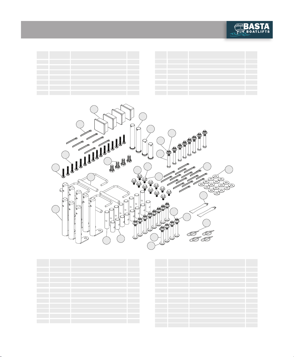
K200-0125 Leg
AA
BB
CC
DD1
DD2
EE
FF
GG
W117-0001
W105-0012
W111-0019
W111-0022
A431-0040
A431-0039
H310-0008
Foot Pad
Side Rail
118” Base Crossmember (2x2k50)
158” Base Crossmember (2x2k50W)
H-frame, Forward
H-Frame, Aft
Hydraulic Cylinder Assembly
H-Frame Arm, Inner
Bunk Rail Assembly, Left
Bunk Rail Assembly, Right
Base Pivot Bushing
Pivot Block
Bunk Board Assembly (part of JJ, KK)
HH
JJ
KK
LL
MM
NN
4
4
4
2
2
2
2
2
8
2
2
16
8
(4)
1
2
3
4
5
6
7
8
9
10
11
12
13
14
15
16
17
18
19
20
21
22
Nut, 3/8-16 Nylock SS
Bolt, Hex Head 3/8-16 x 3-1/2 SS
Bolt, Hex Head 5/16-18 x 1.0 SS
Washer, Flat 5/16 SS
Washer, Lock 5/16 SS
Clevis Pin 3/4 x 5.0 SS
Washer, Flat 3/8 SS
Base Pivot Pin SS
Bolt, Hex Head 3/8-16 x 3-3/4 SS
Ring Cotter Pin 3/4 x.091 SS
Anti-Seize Grease Packet
Cotter Pin 5/16
Cotter Pin 3/16 x 2.0 SS
P Pin SS
Bunk Pin SS
Nut, 3/8-16 Nylock Thin SS
Plastic Cap for 2” ID SQ Tube
Clevis Pin, 3/4 x 3.5 SS
Extension Pin SS
Bolt, Hex Head 1/2-13 x 1.0 SS
Bolt, Hex Head 1/4-20 x 1.75 full thread SS
Washer, Lock 1/4 SS
12
32
12
12
12
2
8
8
16
12
4
8
2
4
8
8
4
2
8
4
16
16
W102-0045
A427-0037
A427-0038
M621-1002
K200-0127
W410-0067
S362-0008
S313-0008
S313-0007
S322-0007
S342-0007
S503-0015
S103-0515
S503-0012
S520-1604
S103-0516
S522-0801
S520-1706
Y356-0003
S532-1801
S503-0020
S362-0108
F730-0021
S503-0013
S503-0011
S103-0705
S103-0338
S322-0006
17
12
21
22
14
20
6
18
8
15 19
11
2
10
2
1
13
35
4
9
7
2
16
23 S313-0013 Flat Washer, SAE 3/4 SS 16
23
PARTS LIST - BOAT LIFT
PAGE 4
1&2 2&10
BB
AA
17
20 14
DD 2&10
BB
1&2
1&2 2&10
BB
AA
AA
BB
1&2
14
20
17
DD
DD2
DD1
10&2
(2x2k50W)
(2x2k50)
2&1
2&1
20 14
CC
7
8
CC
7
16&2
12
16&2
MM
EE
LL
FF
6
GG
9
11
19
HH
HH
JJ
KK
A1
B1
C1
D1
20
10&2
2&10
2&10
2&10
7
7
8
8
8
12
19
19
19
17
17
11
14
18
1&2
21&22
21&22 21&22
21&22
21&22
21&22
MM
MM
MM LL
LL
AA
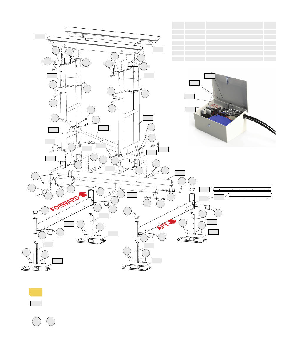
POWER PACKAGE DUAL
#H653-0015
R812-0016
PART NO.
R283-0002
R310-0001
R310-0002
Remote Control Master Unit
DESCRIPTION
Solar Controller
On/Off Switch
Up/Down Switch
1
QTY.
1
1
2
ITEM
A1
B1
C1
D1
E1
F1
R815-0011
C243-0003
Solar Panel Assembly
Enclosure
1
1
PAGE 5
Symbol Glossary for the following pages:
indicates an illustration for a procedure.
indicates a major part described in the parts list
on pages 4 and 5.
or indicate hardware items shown above and
described in the parts list on pages 4 and 5.
Tools needed for the job:
• Tape measure
• Level
• 9/16 ratchet
• 9/16 box-end wrench
• Large slip joint pliers
• Medium sized adjustable wrench
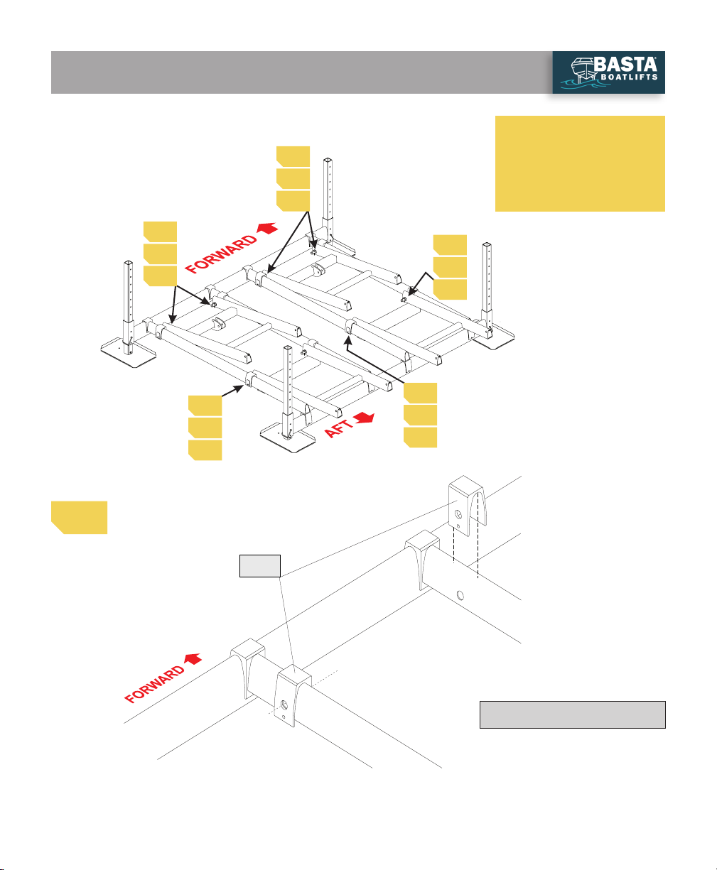
AA
a
1
c+d
9&15&23
9&23
9&15&23
9&23

NOTE: The 3 different holes
shown can be used for pin ‘14’
to allow fine height adjustment
during installation.
Pictured: Steps 1-3
QTY 4: 3/8 x 3.75” bolts (“10”)
QTY 4: 3/8 nylon insert lock nuts (“1”)
QTY 8: 3/8 flat washers (“2”)
QTY 4: leg P pins (“14”)
QTY 4: 1/2 x 1.0” bolts (“20”)
AA
DD
BB 20
2+1
14
10+2
Feet & Legs (4 Places)
Do not tighten bolt ‘20’
until step 17.
Do not tighten any
hardware until step 13.
Use a small amount of
‘moly’ lube on bolt
threads through the
assembly process.
ASSEMBLY INSTRUCTIONS
1
2
1
2
1
1
(2x2k50)
(2x2k50W)
3
3
1
PAGE 6

Forward Crossmember
3Aft Crossmember
QTY 4: 3/8 x 3.75” bolts (“10”)
QTY 8: 3/8 flat washers (“2”)
QTY 4: 3/8 nylon insert lock nuts (“1”)
QTY 4: 3/8 x 3.75” bolts (“10”)
QTY 8: 3/8 flat washers (“2”)
QTY 4: 3/8 nylon insert lock nuts (“1”)
DD
CC
10+2
1+2
1+2
DD
10+2
10+2
Assemble lift on level
ground and adjust legs
so that lift base frame
is level during lift
assembly.
2
3
PAGE 7
Pictured: Steps 4-6
QTY 8: pivot blocks (“MM”)
4
5
6
4
5
6
4
4
4
5
5
5
6
6
6
Pivot Blocks (8 places)
MM
Use a small amount of
‘moly’ lube on bolt
threads through the
assembly process.
ASSEMBLY INSTRUCTIONS
PAGE 8
4

H-frame Bushings (fwd & aft)
H-frames (4 places)
QTY 8: THIN 3/8 nylon insert lock nuts (“16”)
QTY 8: 3/8 flat washers (“2”)
QTY 8: 3/8 x 3.5 bolts (“7”)-Note shorter length!
QTY 8: cotter pins (“12”)
QTY 8: base pivot pins (“8”)
QTY 16: plastic bushings (“LL”)
Forward H-frame is
shown. Aft H-frame
installation is the same.
LL
LL
EE
78
12
16+2
5
6
PAGE 9

Install cylinders with lift
in ‘down’ position.
Cylinders
QTY 2: 3/4 x 3.5” clevis pin (“18”)
QTY 2: 3/4 x 5” clevis pin (“6”)
QTY 4: ring type cotter pins (“11”)
18
Pictured: Steps 7-9
7
7
8
8
9
9
11+6
11+18
Use a small amount of
‘moly’ lube on bolt
threads through the
assembly process.
ASSEMBLY INSTRUCTIONS
PAGE 10
7
SRUW
SRLQWV
GRZQ
Inner Arms (8 places if used)
SRUW
SRLQWV
GRZQ
QTY 4: extension pins (“19”)
QTY 4: 1/4 x 1.75” bolt (“21”)
QTY 4: 1/4 lock washer (“22”)
IMPORTANT
Install cylinder with hose
fittings facing down!
HH
19
Cylinders
21+22
8
9
PAGE 11

LONG AT
FORWARD
END
SHORT
AT AFT
END
PLATES
Right Rail [KK] Left Rail [JJ]
bushing are
pre-installed
FROM FRONT
LOOKING AFT
FROM FRONT
LOOKING AFT
cotter pin
washer
cotter pin
washer
Pictured: Steps 10-12
Complete Step 11 to
raise lift to install
screws for pins. See
Step 12 for details.
10
Bunk Rail Assembly
12
10
12
10
12
15
QTY 8: bunk pivot pins (“15”)
QTY 16: cotter pin (“9”)
QTY 16: 3/4 flat washers (“23”)
KK
10
12
ASSEMBLY INSTRUCTIONS
10
PAGE 12
23
9 23
9
JJ

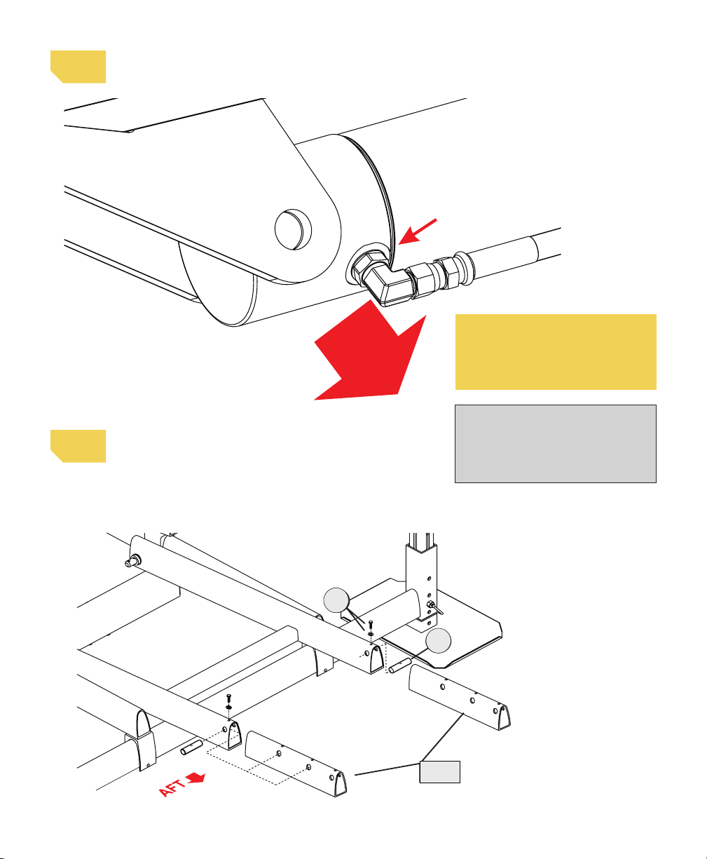
Step 1: Slide the Hydraulic Hose Assembly through the
access hole in the side of the fiberglass enclosure and
attach the ends to their corresponding Quick Couplers.
Ensure each Quick Coupler is fully seated, tight and
with no gap at the connection joint. Complete for each
set of hoses.
Step 2: Remove shipping plug in hydraulic reservoir and
replace with breather plug before first use.
Step 3: Install Battery as shown. Connect the Red Battery
Cable to the positive terminal (+) and the Black
Battery Cable to the negative terminal (-).
Step 4: Before moving into the water, test the lift on dry
ground using the Up/Down Switch and the Key Fob
Transmitters. Inspect the system for leaks.
NEGATIVE BATTERY CABLE
(BLACK)
BREATHER CAP
POSITIVE BATTERY CABLE
(RED)
HOSE ASSEMBLY
FEMALE
QUICK COUPLER
MALE
QUICK COUPLER
Complete Power Unit Package
NO GAP!
IMPORTANT
ONLY ADD FLUID WITH LIFT IN
DOWN POSITION
Hydraulic fluid shown with lift in the
DOWN position
one
inch
1”
The control unit contains two
separate lift control com-
puters. Up to 4 fobs may be
enrolled for each lift.
1
1
2
2
LIFT 1
SWITCH
LIFT 2
SWITCH
CONNECT POWER UNIT
11
PAGE 13

Raise lift to install 1/4
x 1.75” bolts (“21”).
Bunk Rail Assembly
raise lifttoinstall 1/4x1.75” bolts( )"15"
QTY 4: 1/4 x 1.75” bolts (“21”)
QTY 4: 1/4 lock washers (“22”)
12
12
12
12
21+22
21+22
21+22
21+22
Pictured: Step 12
JJ
KK
Use a small amount of
‘moly’ lube on bolt
threads through the
assembly process.
Placement may need
to be modified based
on watercraft draft and
weather conditions.
ASSEMBLY INSTRUCTIONS
12
PAGE 14
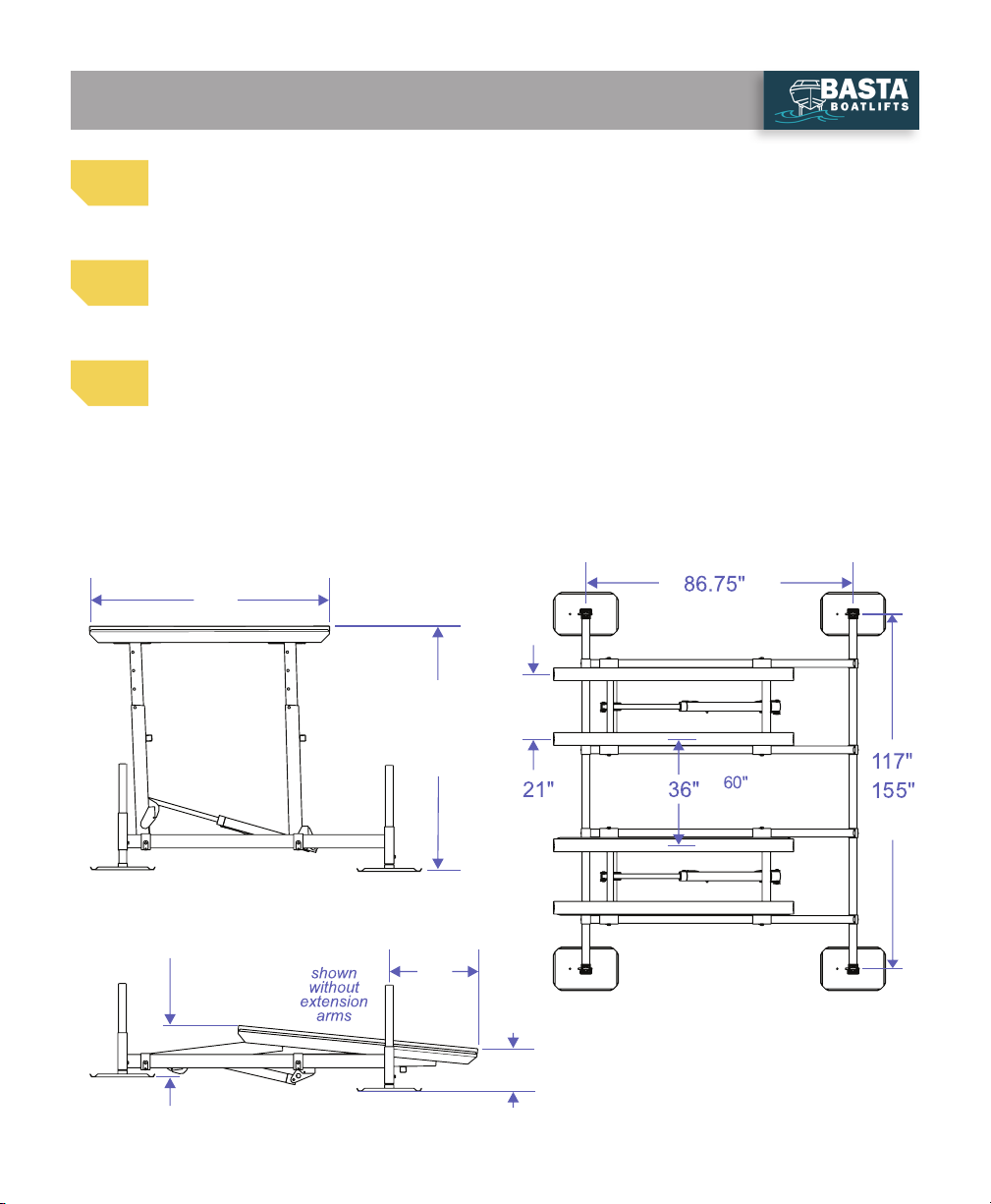
for
2x2kW
[ ]
for
2x2kW
[ ]
without extensions: 59”
with extensions: 65” - 82”
80”
24”
19”
29”
for
2x2kW
[ ]
23”
for
2x2kW
[ ]
30”
without extensions: 62”
with extensions: 68” - 85”
[ ]
for
2x2kW
USE DIAGRAM TO HELP PLACE THE LIFT
Test lift on dry ground for leaks, remote control function and correct operation before moving into
water. Tighten all hardware.
Lower the lift completely, then raise it slightly. Disconnect the Hydraulic Hose Quick Couplers in the
Power Unit box to separate it from the lift.
Move the lift to nal destination. Use this diagram to help place the lift. Lift placement should be so
that the top of the aft end of the bunks are one foot above the high-water mark when the lift is in the
full up position, and one foot below the low water mark, when the lift is in the down position.
13
14
15
PLACEMENT INSTRUCTIONS
PAGE 15
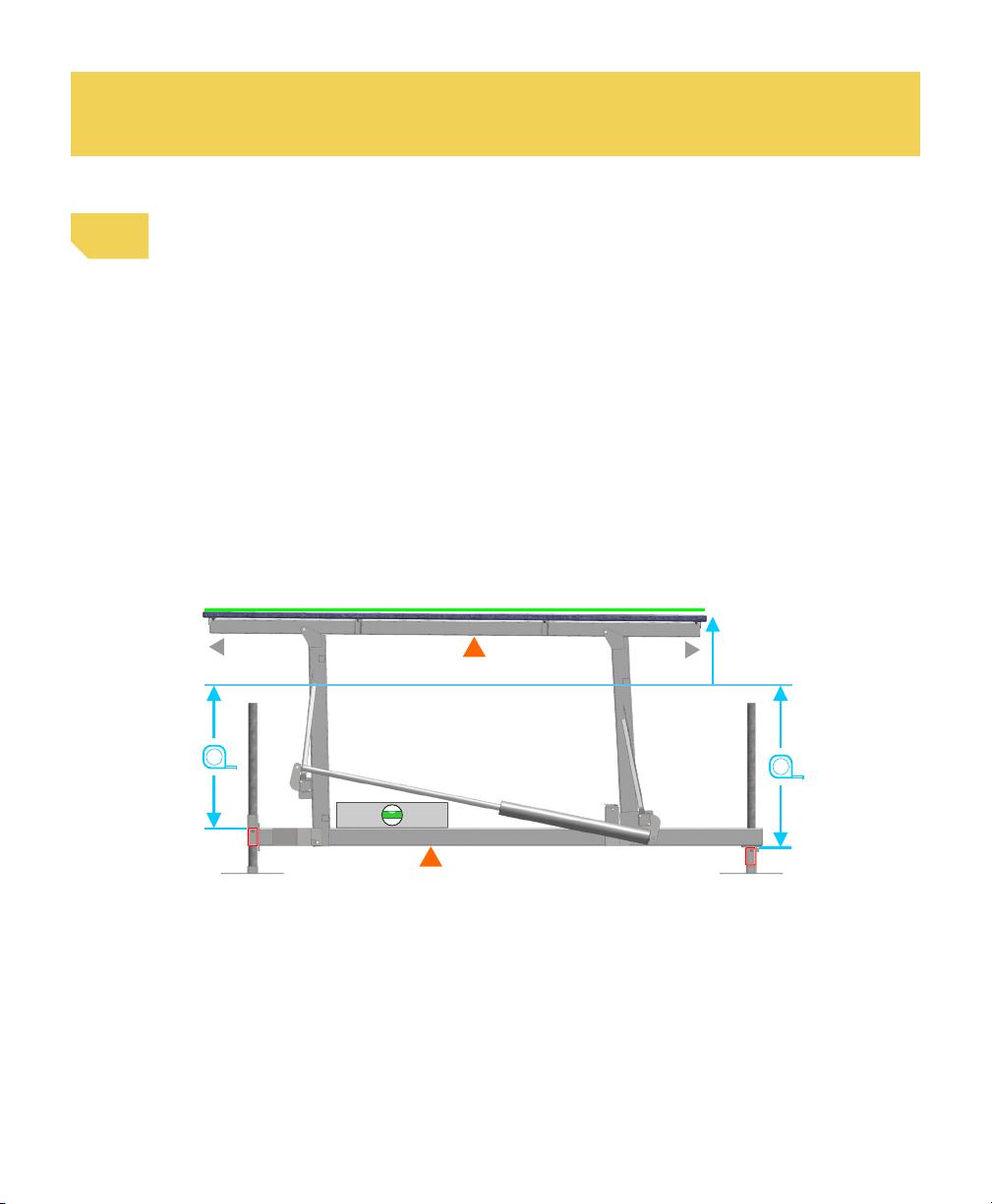
IMPORTANT: The leveling process must be completed to ensure stability of the lift frame
and Over-Center safety lock.
Level the lift following these instructions while referencing image below:
Step 1: Use a tape measure (reference image on right) to determine that the lower
frame is level.
Step 2: If the lower frame needs to be raised start with the lowest corner first then
work your way around the lift in a circle, corner to corner. Adjust the lift legs as needed.
Step 3: To make adjustments, first make sure the lift is properly supported.
Then, loosen the anti-sway bolts, remove the P-pin and raise or lower
the lift crossmember on the leg. Level the lift one corner at a time,
while making sure not to have more than 5” of difference in height
between the corners to prevent binding.
LEVEL
NOT LEVEL
MUST BE LEVEL
FORWARD AFT
FWD
CROSS-
MEMBER AFT
CROSS-
MEMBER
+
4.5”
12”
Surface of Water
Leveling requires a second person to support the crossmember while making adjustments.
If the lift is too heavy for two people, a ratchet strap or winch system will be required to
raise/lower the frame corners.
Contact Basta at 866-GO-BASTA for additional help.
16
PAGE 16
Re-connect the Hydraulic Hose Quick Couplers inside the Power Unit box.
Fully raise lift and finish adjusting the legs so that the base frame is level side-to-side
and forward-to-aft. After the lift is assembled and installed, all fasteners should be
checked for proper tightness and reinspected periodically.
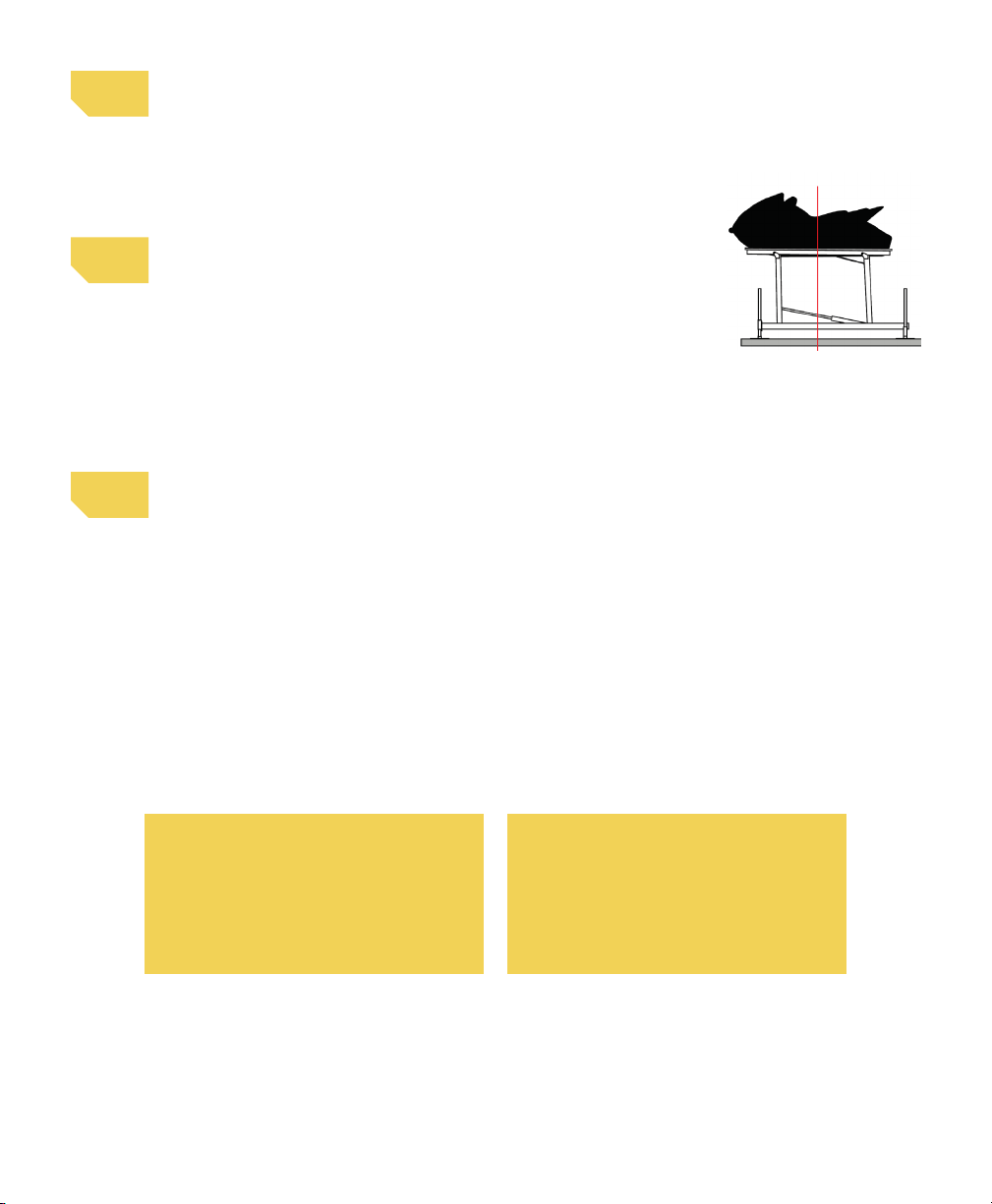
Load the watercraft onto the lift using the following operational
instructions:
1. Align the watercraft so it is centered between the bunks
side-to side.
2. Move the craft forward to position its center of gravity near
the bunks’ centers.
Perform the following adjustments to finalize the lift installation:
1. Disembark and raise the watercraft. If more than two inches of settling occurs,
STOP, carefully lower the lift to remove the watercraft and re-level the lift.
Continue repeating this step until the lift can be raised into the full Over-
Center™ position without settling.
2. Remove the watercraft. Verify that the lift frame is level. Re-level the framework
if necessary.
3. Check all bolts for proper tightness.
Shown: a properly
centered watercraft.
Typically, where your
knee rests will align
with the center of the
bunk.
The lift legs can be cut off above
the leg sockets after installation
for a cleaner look. First, make
sure that the lift has fully settled
and has been re-leveled.
If you plan to add a canopy, relocate the
lift into deeper water, or load a heavier
watercraft in the future, you must keep
the existing leg length.
17
18
19
OPTIONAL
PAGE 17

PAGE 18
IMPORTANT:
• If you purchase a new vessel, make sure does not exceed the weight capacity limits of the lift.
Maximum weight capacity can be found on the cover of this manual and on the H frame of the lift.
• Always turn power unit OFF when not in use.
• Keep inside of power unit box dry.
• To prevent unauthorized use lock box using padlock through the latch hasp.
• Securing your mooring line to the dock may provide additional security should the lift be lowered
inadvertently.
• Leaving your bilge pump on the automatic setting may prevent the accumulation of rainwater in
your vessel and overloading of the lift.
• Service your lift according to recommended Maintenance (page 19).
• Only use Basta Boatlifts approved fluid in lift. Contact Basta Boatlifts or authorized dealer for
approved biodegradable hydraulic fluid.
• When not in use, store the lift in the upright position to prevent it from being an unknown hazard
underwater.
• Store with the power off.
Step 1: Power on. Using the manual switch on the control panel, switch the On/Off switch to the
“On” position.
Step 2: Lower the Lift. Using the Key Fob, unlock the Fob by pressing and releasing the lock button.
Next, press the down button to lower the lift.
Step 3: Carefully guide the watercraft off the lift. Repeat in reverse order upon return.
For more questions or troubleshooting, consult your Authorized Dealer, the FAQs page on
Bastaboatlifts.com or give us a call at 425-641-8911.
OPERATIONAL INSTRUCTIONS

PAGE 19
FOB POWER-UP
After turning on the ON/OFF switch in the dock box, the fob
receiver requires a 5 second delay before the fob is enabled.
FOB OPERATION
Depress the unlock button (lower right), this will allow normal
operation of the fob. The lockout is re-enabled after 60
seconds without a button press. Lift operation using the fob
is limited to 120 seconds of continuous operation. If a longer
cycle is needed it is necessary to release button and then
re-depress.
FOB PROGRAMMING
1. Turn off the ON/OFF switch.
2. Wait 20 seconds.
3. Turn power back on, and within 5 seconds of
power on, press both the UP and DOWN buttons
on the fob simultaneously for 1 second then
release.
4. Repeat steps 1-3 for additional Fobs. Up
to four fobs may be enrolled. If a fifth fob
is enrolled, the first enrolled fob will fall off the list.
BATTERY REPLACEMENT
Fob uses CR2032, 3 volt battery, commonly found online or at
drug / hardware stores. Part numbers vary by manufacturer.
LOW BATTERY LOCKOUT
The remote control contains a low voltage lockout which
is intended to protect the lift’s battery from over-discharge.
When the battery drops below the low battery threshold
during operation, further use of the fob is not allowed. The
manual UP/DOWN switches will allow the lift to operate
when sufficient battery power is present. The lift should
be checked and charged prior to further operation.
TROUBLESHOOTING
If fob worked previously, but
does not currently, replace fob
battery or verify fob battery
has greater than 3v. If fob does
not work after replacement
of fob battery, load test lift
battery ensuring voltage does not drop below 11v while
in use. If you have questions, contact your local dealer or
Basta Boatlifts.
UNDERWATER LIGHTS
The underwater lights are activated whenever the
lift is operated. The lights stay on for 2 minutes
after the lift is operated. The lights may be
manually turned on or off by depressing the lower
left button on the remote fob. When manually enabled the
lights will automatically turn off after
4 minutes. This prevents accidental battery discharge.
REMOTE CONTROL FOB INFORMATION

For more answers to frequently asked questions, visit:
bastaboatlifts.com/support/
frequently-asked-questions/
Q: THE BATTERY WILL NOT HOLD A CHARGE
A: Verify that the loaded watercraft is not exceeding the
weight capacity of the lift. If the battery is a
flooded-cell type, check the electrolyte level.
A: Ensure the solar panel is properly connected.
A: Re-align the solar panel for proper exposure to
the sun.
A: Recharge the battery with a 10 amp charger and
check the charge again.
A: Have the battery tested. It may be old and require
replacement.
A: If the lift is being used frequently during the day, it
may be necessary to use a 110-volt maintainer/charger.
Q: THE REMOTE CONTROL IS NOT
FUNCTIONING
A: The battery in the key fob transmitter may be
low. Replace it with a new lithium CR2032. These
are widely available at variety, hardware and even
grocery stores. Polarity is marked on the battery
holder.
A: Verify that the power unit battery is charged
and connections are tight.
A: Reprogram the remote key fobs.
Q: THE PUMP DOESN’T RUN
A: Check the battery charge and recharge if
necessary.
A: Check the battery connections, clean and
re-secure if necessary.
Q: THE PUMP RUNS, BUT THE LIFT
DOESN’T MOVE
A: Check the ‘Quick Couplers’ in the Power Unit.
If they are not screwed together tight enough,
built-in check valves will not allow fluid to flow.
See Page 12.
A: Check the fluid level. See Page 19.
Q: DOES THE LIFT HAVE TO GO ALL THE
WAY UP?
A: YES - in order for your lift to function as
intended the lift must ALWAYS be stored in the full
upright position when the watercraft is unattended.
Q: IS MY VESSEL SECURE?
A: Yes, once you verify that the lift is Over-Center™,
switch off the power and lock the power
unit box, there is less chance of theft.
Q: DO I NEED A MOORING LINE?
A: Under most circumstances one mooring line is
sufficient to prevent the watercraft from drifting away
if the lift is inadvertently lowered or the water level
rises.
Q: HOW MUCH SUN DOES THE SOLAR
PANEL NEED?
A: The panel should receive constant sun for at
least 8 hours a day.
Q: HOW DO I CHANGE THE HYDRAULIC
FLUID?
A: Our fluid should not require replacement for
a considerable amount of time. If yours has been
contaminated or the hydraulic power unit has
been replaced, visit our web site at
www.gobasta.com for detailed instructions.
Q: HOW DO I KNOW WHEN IT IS TIME TO
CHANGE THE FLUID?
A: Basta Boatlifts’ hydraulic fluid lasts between 3-6 years
depending on usage. If you begin to hear an increased pitch
in the sound of your pump motor, it is likely time to flush your
hydraulic fluid. You can also tell by the clarity of the fluid.
Fluid that is ready to be changed will be dark in color or cloudy.
New fluid is clear.
Q: WHAT IF I GET A NEW VESSEL?
A: Re-leveling the lift may be necessary.
A new lift will be required if the watercraft exceeds the
weight capacity of your current lift.
PAGE 20
TROUBLESHOOTING AND FAQ
This manual suits for next models
1
Table of contents
Other Basta Boatlifts Lifting System manuals

Basta Boatlifts
Basta Boatlifts Over-Center 12k64 User manual

Basta Boatlifts
Basta Boatlifts 1.4k60 User manual

Basta Boatlifts
Basta Boatlifts Over-Center 18k59 User manual

Basta Boatlifts
Basta Boatlifts Over-Center 7k51 User manual

Basta Boatlifts
Basta Boatlifts Over-Center 36k60 User manual

Basta Boatlifts
Basta Boatlifts 8k53 User manual

Basta Boatlifts
Basta Boatlifts Over-Center 4.5k37 User manual

Basta Boatlifts
Basta Boatlifts Over-Center BM4050SP User manual

Basta Boatlifts
Basta Boatlifts Over-Center 10k53 User manual

Basta Boatlifts
Basta Boatlifts Over-Center 4.5k37 User manual


