TC FLUID CONTROL KMS-2 User manual

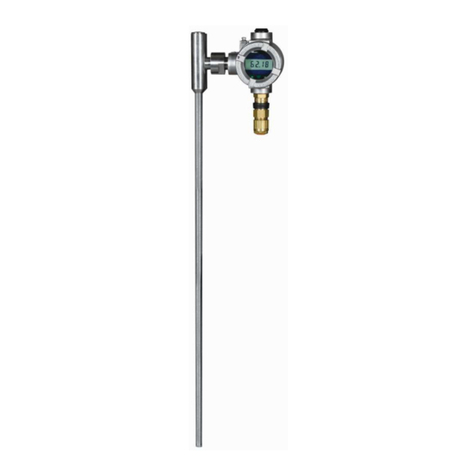
KMS-2 Magnetostrictive Level Transmitter
Please retain for future use
Revision H File Exd kms-2 iom revH.doc
Installation and operating manual

INDEX
Symbols Used …………………….………………………………………1
Safety Information …………………………………………………………………….1
Introduction and Scope of use …………………………………………….2
Output signals ……………………………………………………….…….2
Installation …………………………………………………………….……………….3
Magnetic Level Gauge Application …………………….……………….4
Immersion Application …………………………………….……………….5
Electrical Connections …………………………………………………………….6
Connection Cable Selection …………………………………………………….6
Adjustment and Configuration …………………………………………………….7
Painting and coatings ………………………………………………………………..9
Certification …………………………………………………………………………….10
Special Conditions for Safe Use ……………………………………………………...10
Fault Analysis Sheet …………………………………………………………….12
Maintenance …………………………………………………………………………….12
Technical Data …………………………………………………………………….13

KMS-2/Exia/Exd Transmitter
Installation and Operating Manual
Page 1 of 16 KMS-2:Exia/Exd IOM Rev H 18/05/10
ATEX
Symbols Used
The following symbols are used in these operating instructions:
Warning: If ignored injury or damage to property can occur.
Danger: If ignored serious injury or damage to property can occur.
Caution:Failing to comply with these instructions can lead to malfunction
of or damage to the Level Transmitter.
Ex Applications
Instructions which must be complied with when the unit is used in potentially
explosive environments and to meet the requirements of the EC type
examination certificate.
Information
Facts and information concerning proper operation of the
KMS-2 Level Transmitters
Instructions for electrical installation
Information on proper electrical installation.
Safety information
Read these instructions before installation and putting into operation.
Installation commissioning and maintenance should only be carried out by suitably qualified personnel in
conjunction with these instructions.
Comply with the relevant safety regulations when using the equipment.
The transmitter must not be modified as this will invalidate the warranty and or the product certification.
Measures must be taken to prevent risks to persons and property in the event of a defect.
Do not operate the Level Transmitters in the immediate vicinity of strong electromagnetic fields (minimum
distance: 1 m) as this may give rise to incorrect readings.
Comply with the maximum current and voltage ratings as stated in the technical data section.
For hazardous area applications installation of this unit must be in compliance with the applicable
National requirements i.e. EN60079-14:

KMS-2/Exia/Exd Transmitter
Installation and Operating Manual
Page 2 of 16 KMS-2:Exia/Exd IOM Rev H 18/05/10
ATEX
INTRODUCTION
The KMS-2 transmitter is a 4 to 20 mA loop powered transducer for measuring the level of liquid in a
vessel either directly (immersion application) using an annular float, or indirectly by mounting on a
magnetic level gauge.
The Exia intrinsically safe version can be used in all hazardous area zones when connected through an
approved isolation barrier.
The Exd Gb explosion proof version is suitable for Zones 1 and 2 (ATEX category 2 & 3) applications.
This transmitter is NOT intended to interface directly with Zone 0 areas. When used with Zone 0 tanks
etc (EPL Ga), the probe must be installed in accordance with IEC 60079-26 (i.e. in a separate ventilated
pocket and/or fed from an intrinsic safety supply)
The transducer consists of a stainless steel tube, containing the Magnetostrictive measuring element,
and an aluminium or stainless housing containing the electronic circuit board.
The unit operates by sending an electrical pulse down the sensing element; the resulting magnetic field
reacts with the field from the magnetic float to produce a return signal. The time taken for the return
signal to be detected enables a level measurement to be made since the precise velocity of the return
signal along the sensing element is known.
Output Signals
Analogue Output: The process variable and error status are transmitted over the current loop with values
as shown in table 1.
LCD Indicator: When fitted the display provides local indication of the process variable ranged 0-100% of
measured range. Additional error modes and calibration status as shown in Table 1
LED: Provide local indication during calibration when the optional LCD is not fitted.
Outputs
Mode Function ANALOGUE LCD (%) Zero LED Span LED
NORMAL Measuring 4-20mA 0.000/100.0 Off Off
Zero 4mA 0 On Off
Fixed Output Span 20mA 100 Off On
Start 12mA CAL Flash Flash
Zero set 12mA CAL On Off
CALIBRATION
Span set 12mA CAL Off On
Low level 3.5mA ERR.L Off Off
Return Pulse
Missing 23mA ERR.H Off Off
ERRORS Calibration
Failure 12mA CAL Fast Flash Fast Flash
Table 1
Instrument output status indication
The Low Level alarm must be enabled as shown in the configuration section. When set
the output signal will change to 3.8mA if the float drops more than 13mm below Zero
point.

KMS-2/Exia/Exd Transmitter
Installation and Operating Manual
Page 3 of 16 KMS-2:Exia/Exd IOM Rev H 18/05/10
ATEX
INSTALLATION GENERAL.
Magnetic Level Gauge Applications
The unit should be fitted to the level gauge with reference to Fig1 using the mounting clips and insulation
(if required) supplied. The unit should be positioned such that the XXXX marks around the circumference
align with the upper and lower vessel connection points.
Ensure that the sensing tube is not distorted or strained during installation
The fixing clips should be spaced evenly along the length of the tube with a maximum centre distance
1000mm
If it is required to remove the transmitter for maintenance work ensure that any
insulation is correctly fitted during reassembly to ensure operating temperatures are
maintained within the range specified on the EC type approval certificate.
Immersion or in tank installation
The transmitter should be fitted to the tank with reference to Fig.2. The distance between the tank
connection and electronic housing will vary dependent on temperature and for a weld on connection be
factory set. For Exd applications, the probe assembly is inserted into a vented sleeve configuration.
Caution
When using an adjustable sealing gland ensure that the maximum ambient temperature
for the electronic housing is not exceeded. (See technical data section).
Dependent on the length of the sensor tube an anchor point may be required at the bottom of the tank.
Where the transmitter is supplied with an adjustable gland care must be taken to
ensure that the electronic housing temperature is maintained within that is specified
in the hazardous area certificate. Please consult the sales office.
Use caution when handling the transmitter to ensure the probe is not bent during installation. A bend in
the probe could prevent the float from travelling freely up and down and it could damage the
magnetostrictive wire fitted inside.
Immersion applications are calibrated prior to installation by positioning the float at the desired 4 mA & 20
mA points.
Verify that the float will pass through the vessel opening. Note: the float is held on the probe by a C-clip
inserted into a groove machined into the tip of the probe. The float can be attached or removed by
removing and reinserting the C-clip. Ensure that the floats orientation is correct.
For Exd applications, the probe assembly is inserted into a vented sleeve assembly.

KMS-2/Exia/Exd Transmitter
Installation and Operating Manual
Page 4 of 16 KMS-2:Exia/Exd IOM Rev H 18/05/10
ATEX
Fig 1
KLINGER
RED WAFERS IN B OX
INDICATE DAMAGED FLOAT.
BOTTOM SIDE MOUNT
SECTION SHOWING
TYPICAL TRANSMITTER
MOUNTING ARRANGEMENT.
TOP MOUNTED
HEADSHELL UNIT
TOP SIDE MOUNT

KMS-2/Exia/Exd Transmitter
Installation and Operating Manual
Page 5 of 16 KMS-2:Exia/Exd IOM Rev H 18/05/10
ATEX
Typical Installation When Fitted to Magnetic Level Gauge
For Zone 0 areas, refer to the section covering ‘Special Conditions For Safe Use’ under Certification.
Fig 2
Immersion Application
Ensure that the PFA/PTFE washer is correctly fitted to prevent the risk of sparking if the
float was to hit the stop.
Ensure that the electronic assembly is maintained within the certified ambient
temperature range consult sales office to determine correct offset.

KMS-2/Exia/Exd Transmitter
Installation and Operating Manual
Page 6 of 16 KMS-2:Exia/Exd IOM Rev H 18/05/10
ATEX
ELECTRICAL CONNECTION
Unscrew the lid to gain access to the rear terminal enclosure; the terminal block can then be removed to
facilitate connections.
Select the correct cable entry point dependent on the orientation of the sensor. The connection cable
should be bought in through an M20 gland suitable to maintain the required IP rating, and then
connected to the + and – terminals.
To prevent the risk of moisture ingress ensures that the connection cable is led downward in front of the
cable gland.
Do rotate the electronic housing relative to the orientation of the probe assembly as this would invalidate
the warranty and could cause damage to the sensor cables.
Cable Selection
The connection cable should be a twisted pair type suitable for the expected ambient conditions.
When a screened cable is used, the screen should be connected to the internal earth connection
provided. An external Earth is also provided.
Hazardous area Installation
The installation of this unit must be in compliance with the applicable national
requirements i.e. EN60079-14.
Intrinsically Safe Circuits
The connection cable shall be identified to prevent confusion with non-intrinsically safe circuits where a
colour code is used it should be light blue.
The total inductance and capacitance of the cable shall not exceed the values stated on the intrinsically
safe control device for the required gas group.
The connection cable should be bought in through the M20 cable entry via a suitable gland as necessary
to maintain the required IP rating (minimum IP54).
When refitting the lid ensure that the sealing gasket is correctly fitted into the lid recess.
Exd Area Installation.
WARNING – Do not open when an explosive atmosphere may be present.
Exd cable entry devices shall be a certified cable gland, any unused cable entry holes to be closed using
a certified stopping device. Standard cable entries are M20 x 1.5 mm (6H, 6g) with a minimum IP rating
of 54.
Note: In an explosive environment, the cover lid must remain fitted and locked into position while
energised. Exd lid covers are required to be locked into position using the grub screws provided.

KMS-2/Exia/Exd Transmitter
Installation and Operating Manual
Page 7 of 16 KMS-2:Exia/Exd IOM Rev H 18/05/10
ATEX
Fig 3 Cable entry via M20 gland Fig 4 Connection Details
Adjustment and Configuration:
The unit is normally set at the factory to the required specification
•Range adjustment and output inversion
•Low Level Alarm Select
Fig 5
Internal layout of case showing
Local Display and calibration switches
Range Adjustment
The measuring range of the unit is set at the factory.
If the default range is unsuitable or adjustment is required the following procedure should be followed.
With reference to Fig. 5
1. Set the float to the minimum level
2. Press the ‘Span’ and ‘Zero’ buttons until both LED,s flash alternatively (output 12mA)
3. Release buttons
4. Press the ‘Zero’ button until the ‘Zero’ LED stays on
5. Wait until the ‘Zero’ LED extinguishes. (output 4mA)
6. Set the float to the maximum level.
7. Press the ‘Span’ and ‘Zero’ buttons until both LED’s flash alternatively (output 12mA)
8. Release buttons
ZERO SPAN
OFF
1 2
28V dc
MAX
K&TC
PCB620
REV D
+
E
+

KMS-2/Exia/Exd Transmitter
Installation and Operating Manual
Page 8 of 16 KMS-2:Exia/Exd IOM Rev H 18/05/10
ATEX
9. Press the ‘Span’ button until the ‘Span’ LED stays on
10. Wait until the ‘Span’ LED extinguishes. (output 20mA)
If the optional LCD is fitted the display will read ‘CAL’ during the setting process.
The measuring range can be set within the factory limits with a maximum turndown of 50%,
If an error is detected during the ranging process the unit will default to the previously
saved values the Relevant LED will flash if ranging failed.
Inverse output
The output is normally set so that the 20mA point is at the Head shell end. If it is required to mount the
head shell at the bottom the output can be inverted by following procedure.
1. Move the float to approximately 50% of range
2. Set the ‘Zero’ level as 2-5 above
3. Move the float to the required maximum level
4. Set the ‘Span level as 7-9 above,
5. Move the float to the required minimum level zero level.
6. Set the ‘Zero level as 2-5 above.
The unit will then automatically invert the output.
Caution
The float failure and write protect switches should be set to the ‘OFF’ position before
adjustment to the ranging are made, and reinstated as necessary afterwards.
It is important that the float is kept stationary for approximately 10 seconds before and
after operation of the calibration buttons to ensure that the output signal has stabilised
to the correct value.
Low level alarm
The Low Level alarm output signal will change the output to 3.8mA if the float drops more than 13mm
below Zero point. When off the output will remain at 4mA below the zero point until the return signal is
lost i.e. the sensor is no longer sensing the magnetic field then output will change to 22mA.
1) Write Protect
Up Range setting inhibited
Down
2) Alarm Function
Up Low Level (3.8mA)
Down No Alarm Output
Remains at 4mA
Fig. 6
Configuration switches
Caution
Turn power off before changing alarm switch settings to prevent unexpected changes in
loop current. Ensure that the write protect is set to ‘ON’ after changes to range
adjustments.
FIXED OUTPUT
To allow for loop calibration the transducer output can be fixed to either 4 or 20mA. The zero or span
button should be depressed until the respective LED lights; the output will then remain static. To reset to

KMS-2/Exia/Exd Transmitter
Installation and Operating Manual
Page 9 of 16 KMS-2:Exia/Exd IOM Rev H 18/05/10
ATEX
normal operation either depress the opposite button or cycle the power.
Coatings and painting.
The maximum non-conductive coating thickness allowed for the transmitter housing is limited to 200
microns. All coated Exd units must be earthed accordingly, an external earth post is provided.

KMS-2/Exia/Exd Transmitter
Installation and Operating Manual
Page 10 of 16 KMS-2:Exia/Exd IOM Rev H 18/05/10
ATEX
EMC
In accordance to EC council directive 89/336/EEC
Emissions EN 61326:2004 (Class B)
STANDARD DESCRIPTION PORT RESULT
EN 61326 Radiated Emissions Enclosure Pass
EN 61326 Conducted Emissions Not applicable Not Tested
Immunity tests to EN 61326: 2004 A1, A2, and A3
STANDARD DESCRIPTION PORT RESULT
61000-4-2 Electrostatic Discharge Enclosure Pass
61000-4-3 RF Electromagnetic Field Enclosure Pass
61000-4-4 EFT/ Burst DC Port Pass
61000-4-5 Surge DC Port Pass
61000-4-6 Conducted RF DC Port Pass
61000-4-8 Magnetic Field Enclosure Not Tested
61000-4-11 Voltage Dip/ interruptions Not applicable Not Tested
CERTIFICATION
Certificate No’s. Baseefa 09 ATEX 0085X IECEx BAS09.0027X
Explosion protection Type: Ex d
Gas Group: IIC
ATEX Approval Type: II 2G
Notified Body No. CE 1180
Special Conditions for Safe Use:
•The integral probes may be used with process vessels at elevated temperatures up to 250oC,
however the connection/transmitter head shall be ‘stood-off’ and the Temperature Class adjusted
as follows :-
Temperature
Class Ambient
Temperature
Maximum
Probe
Temperature
Minimum Stand-off
Distance
T6 -50oC to +60oC 40oC 0
T6 -50oC to +40oC 60oC 75mm
T5 -50oC to +60oC 80oC125mm
T4 -50oC to +60oC 120oC175mm
T3 -50oC to +60oC 180oC250mm
T2 -50oC to +60oC 250oC325mm
•The probes are not intended to interface directly with Zone 0 areas. When used with Zone 0

KMS-2/Exia/Exd Transmitter
Installation and Operating Manual
Page 11 of 16 KMS-2:Exia/Exd IOM Rev H 18/05/10
ATEX
tanks etc. (EPL Ga), the probe shall be installed in accordance with IEC 60079-26, [i.e. in a
separate ventilated pocket and/or fed from an I.S. supply].
FAULT ANALYSIS SHEET
Problem Possible Fault Action
Supply Voltage to low Check voltage and adjust
accordingly
Supply Connections reversed Swap supply cables
Cables/Connecting circuit
faulty Rectify as required
Zero reading i.e. 0mA
Faulty Unit Consult Technical Sales
Reading Greater than 22mA Supply voltage to high Adjust voltage to less than
28V
Float damaged (sunk) Fit new floatContinual Reading of
3.8mA (alarm) Chamber empty Open check valves
Float magnetic field not being
sensed Check gap distance between
chamber and transmitter
Unit incorrectly calibrated Carry out calibration
procedure
Continual reading of
22mA(Alarm)
Float Under magnetised Check with spare float if
available
Float stuck or damaged Check against visual display
if fitted. Check float condition
Output static at a particular
level External magnetic
interference Check for external magnetic
devices in vicinity
“XXXX” marks not inline with
vessel connections Realign transmitter marks
correctly
4-20mA not proportional to
liquid level S.G range of float incorrect for
media type Check S.G etched on float
against media S.G
Table 3
Fault Analysis
MAINTENANCE
The unit contains no user serviceable parts; therefore no routine maintenance is required.
•Where the case of the device may be subjected to impact or friction, periodic examination is
required to ensure that the integrity of the stove enamelled finish is maintained.
•When used in immersion applications the sensor tube must be kept clean to prevent the float
“sticking”.

KMS-2/Exia/Exd Transmitter
Installation and Operating Manual
Page 12 of 16 KMS-2:Exia/Exd IOM Rev H 18/05/10
ATEX
TECHNICAL DATA
Materials
Measuring probe: - 316L
Housing: - Epoxy coated aluminium or 316L Stainless steel
Cable entry
Thread Size: - M20x1.5mm
Connection conductor size: - 0.5mm² - 2.5mm²
Supply voltage (Nominal 24VDC)
Minimum 12V
Maximum 28V
Current Output
Measured Current range: - 4-20mA ± 0.1%
Alarm Current: - 3.8mA…. 22mA
Upscale 22mA (Fault)
Downscale 3.8mA (Low level)
Fixed Output 4 or 20mA ± 0.1%
(For loop calibration)
Operating Temperatures
(See certification section for details when used in a potentially explosive atmosphere)
Ambient range: - -50°C / + 60°C (-5°C / +60°C When LCD Fitted)
Process range: - -50°C/ +250°C
Fig 7
Ambient verses process temperature for standard transmitter

KMS-2/Exia/Exd Transmitter
Installation and Operating Manual
Page 13 of 16 KMS-2:Exia/Exd IOM Rev H 18/05/10
ATEX
Where ambient conditions are outside this range additional insulation or shielding will be required please
consult sales office

TC FLUID CONTROL LTD
UNIT 4 THE INTERCHANGE
WESTED ROAD
SWANLEY
KENT
BR8 8TE
UK
TEL ++44(0) 1322 622400
FAX ++44(0) 1322 660621
E-mail instruments@tc-fluidcontrol.com
Other manuals for KMS-2
1
Table of contents
Other TC FLUID CONTROL Transmitter manuals
Popular Transmitter manuals by other brands

Emerson
Emerson Rosemount 3051 quick start guide

GoPass
GoPass AVL-921 Hardware installation manual

Foxcom
Foxcom SatLight 7310D Installation and user guide
MERIT TECHNOLOGY
MERIT TECHNOLOGY MT-305 quick start guide
Extron electronics
Extron electronics FOX II T DP 4K Setup guide
PR electronics
PR electronics PRetrans 6334 manual
