Salcom 20-62 User manual

Copyright © 2020 Sea Air and Land Communications Ltd. All rights reserved.
20-62
VHF / UHF Transmitter with Ethernet
PRODUCT MANUAL
Version 1.3.2
March 2020

P a g e | 1
20-62 VHF & UHF TRANSMITTER
Product Manual
Sea Air and Land Communications Ltd, 10 Vanadium Place, Addington, Christchurch 8024, New Zealand March 2020
Warranty and Disclaimer
Salcom products are warranted for a period of 12 months from the date of purchase against
faulty materials and workmanship.
If any fault should occur, the unit should be returned to the vendor, freight pre-paid. Please
include a description of the fault to assist with prompt return. Any unauthorised alterations or
repairs will invalidate the warranty.
We reserve the right to change products, specifications, and installation data at any time,
without notice.
All information provided in this document is carefully prepared and offered in good faith as a
guide in the installation and use of Salcom products. Installers must ensure that the final
installation operates satisfactorily within the relevant regulatory requirements. Salcom accepts
no responsibility for incorrect installation.
Please refer to the product specifications for specific certification information.

P a g e | 2
20-62 VHF & UHF TRANSMITTER
Product Manual
Sea Air and Land Communications Ltd, 10 Vanadium Place, Addington, Christchurch 8024, New Zealand March 2020
Contents
Warranty and Disclaimer................................................................................................................................1
Product Overview............................................................................................................................................3
Connectors and Indicators ............................................................................................................................5
Physical Dimensions.........................................................................................................................................6
20-62 Installation and Quick Start Guide......................................................................................................7
Salcom Protocol ..............................................................................................................................................9
Sacoto Configuration Tool - Quick Start Guide.........................................................................................10
Configuring the 20-62 using Sacoto............................................................................................................13
Salcom UDP/TCP Test Tool............................................................................................................................23
Virtual Serial Port over Ethernet ...................................................................................................................24
Store & forward systems................................................................................................................................26
Simulcast Modulation Delay ........................................................................................................................28
Over-Temperature Cutout ...........................................................................................................................30
Aerial Mismatch .............................................................................................................................................31
Antenna Selection and Installation.............................................................................................................33
Supported Messaging Protocols..................................................................................................................34
Trouble Shooting ............................................................................................................................................37
Glossary...........................................................................................................................................................38
Accessories and Related Products .............................................................................................................39
Technical Specifications...............................................................................................................................40
How to Contact Us ........................................................................................................................................42

P a g e | 3
20-62 VHF & UHF TRANSMITTER
Product Manual
Sea Air and Land Communications Ltd, 10 Vanadium Place, Addington, Christchurch 8024, New Zealand March 2020
Product Overview
The Salcom 20-62 is a 5 Watt, stand-alone FSK transmitter with a POCSAG encoder and external
NRZ input. Models are available for the VHF or UHF bands. Each model covers its full specified
frequency range without the need for any mechanical adjustments or additional calibration. The
output power level can be programmed from 50mW to 5W.
Key Features:
POCSAG encoder: The 20-62 provides a built-in POCSAG encoder, supporting 512 and
1200 baud with numeric and alphanumeric messages. The 20-62 POCSAG encoder can
queue up to 40 messages for transmission, with a total of up to 1000 characters combined.
Individual messages can be up to 240 characters long.
External NRZ input: Externally generated NRZ data can be transmitted using the external
modulation input and PTT input.
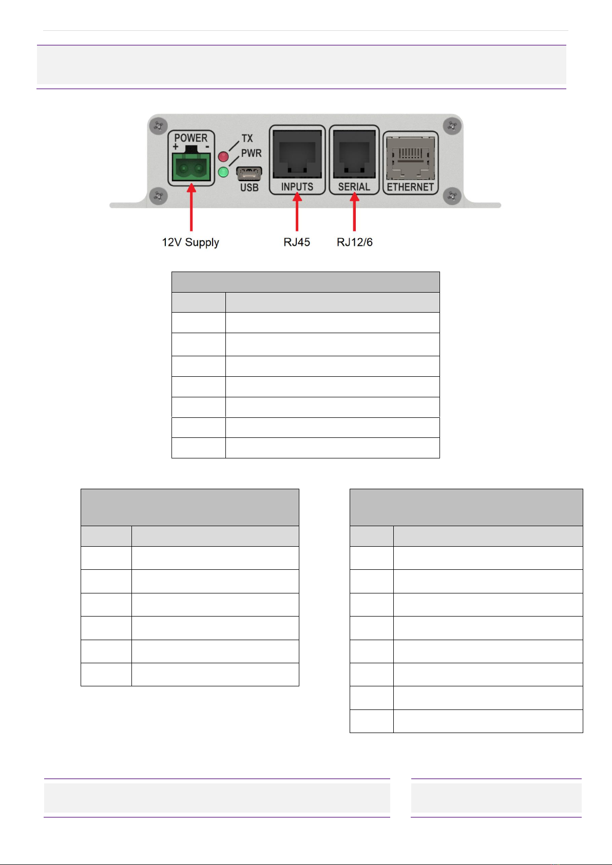
USB, Serial and Ethernet ports: The 20-62 may be controlled through four ports: two physical
RS-232 ports, one USB serial port, and one TCP/IP or UDP Ethernet connection.
Message protocols: The 20-62 supports a wide range of messaging protocols, including
Salcom protocol, TAP (PET), TNPP, and many more. The 20-62 can support up to four
different messaging protocols concurrently, one on each port. For more details please
refer to the protocol list provided in this manual.
Triggered messages: Messages may be triggered using four input pins, the battery level,
or a regular watchdog timer. Messages may be triggering on rising or falling edges with a
programmable de-bounce delay. The input states and the battery state may also be
transmitted at startup, or at regular intervals with the watchdog timer. These pre-
programmed messages may be up to 40 character long.
Sacoto configuration tool: The Salcom “Sacoto” configuration software allows full
configuration of all functions of the 20-62 transmitter via any serial port, the USB port, or the
Ethernet port. Note that the Ethernet port cannot be used to configure the Ethernet port!
Store & Forward repeater: The 20-62 can be configured to operate as a store & forward
repeater when used with a separate paging receiver such as the Salcom 12-84. Messages
received by the receiver can be retransmitted by the 20-62 to extend the paging
coverage area. The 20-62 provides features to prevent loops and multiple retransmissions,
and can provide a delay at the originating transmitter to allow time for repeaters to
forward messages without interference.
Extended database tool: Some messaging protocols use a database of CAP codes that
are stored within the 20-62. Sacoto supports up to 100 CAP codes, which is sufficient for
most applications. However, if more are required an extended database tool is available
to allow up to 1000 CAP codes. This is a useful feature when used with the Salcom 12-36
Paging Telephone Voice Interface.

P a g e | 4
20-62 VHF & UHF TRANSMITTER
Product Manual
Sea Air and Land Communications Ltd, 10 Vanadium Place, Addington, Christchurch 8024, New Zealand March 2020
Simulcast modulation delay: A simulcast synchronizing delay can be applied to externally
generated NRZ data. This delay can be configured to be between 10uS and 2550uS to
account for a difference in propagation delay in overlapping coverage areas. Note that
this features uses a different modulation input pin to the undelayed NRZ modulation input.
Aerial mismatch detection: When enabled, the 20-62 can provide serial reporting of a
disconnected or damaged antenna, and reduce output power to protect the transmitter.
The feature must be self-calibrated for each installation before use.
Over-temperature cutout: The 20-62 is protected against overheating. If the transmitter
operates for extended periods in a hot environment, a protective thermal cutout may
operate to reduce the output power to a safe level. It will reset when the unit temperature
has fallen to below 70C.

P a g e | 5
20-62 VHF & UHF TRANSMITTER
Product Manual
Sea Air and Land Communications Ltd, 10 Vanadium Place, Addington, Christchurch 8024, New Zealand March 2020
Connectors and Indicators
Pin 1 on left side when viewed from front, as above.
Table 1: Connectors and Indications (L-R)
Item
Description
1
12V Supply
2
Transmit LED (Red)
3
Power LED (Green)
4
USB
5
Inputs (RJ45)
6
Serial ports x 2 (RJ12)
7
Ethernet
Table 2: Serial Connector (RJ12/6)
Table 3: Input connector (RJ45)
Pin
Connection
Pin
Connection
1
Ground
1
PTT OUT, 50mA max
2
Reserved
2
Ground
3
RS232 Port 2 TX
3
Trigger Input 4
4
RS232 Port 2 RX
4
Trigger Input 3
5
RS232 Port 1 TX
5
Trigger Input 2
6
RS232 Port 1 RX
6
Trigger Input 1
a
7
PTT Input for NRZ operation
8
Modulation Input for NRZ
operation

P a g e | 6
20-62 VHF & UHF TRANSMITTER
Product Manual
Sea Air and Land Communications Ltd, 10 Vanadium Place, Addington, Christchurch 8024, New Zealand March 2020
Physical Dimensions
The 20-62 has an extruded aluminum case with a mounting flange and screw slots. A
dimensioned drawing is provided below.

P a g e | 7
20-62 VHF & UHF TRANSMITTER
Product Manual
Sea Air and Land Communications Ltd, 10 Vanadium Place, Addington, Christchurch 8024, New Zealand March 2020
20-62 Installation and Quick Start Guide
Power Supply
Power is connected to the green “Power”connector on the front panel with the polarity as
shown. Nominal supply voltage is 13.8V DC, but may vary between 10.8V and 15V. The power
source must be reasonably noise free. The 20-62 is protected against reversed polarity.
Antenna Installation
The antenna is connected to the SMA connector on the rear panel. Installing the antenna
outside, clear of obstacles, and high above the ground will most likely provide the best radio
coverage.
The antenna should present a nominal load of 50Ω, with a VSWR of better that 1.8:1. The
transmitter output power may be affected by a poorly matched antenna (ie if not 50 ohms at
the transmitter frequency).
The 20-62 is designed to operate reliably over large distances, however the actual distance can
vary depending on antenna height and position, obstructions, antenna cable length, local radio
interference, antenna specifications, and the sensitivity of the receiver.
Important! To comply with FCC Controlled/Occupational Exposure Limits the aerial must be
positioned or mounted to operate at least 0.26 metres (0.853 ft) away from operational staff and
0.57 metres (1.87 ft) away from the general public as a safeguard against radiated emissions.
Serial connections
The 20-62 may be configured to operate without a serial connection, transmitting regular
messages, or transmitting messages in response to trigger inputs or the battery level.
For other messages, the RJ12 serial connector provides two RS-232 serial ports. Serial connection
may also be made via the USB connector or the Ethernet port.
RS-232 serial ports
Two RS-232 serial ports are provided on the RJ12 serial connector. A standard 6 way RJ12 6P6C
cable and splitter may be used to separate the two ports if required.
The Salcom 12-45-0000 adaptor converts port 1 of the RJ12 to a DB-9 connector. The Salcom 12-
45-2000 converts port 2 of the RJ12 to a DB-9 connector.
The RG12 pin-out is provided above for custom cables.

P a g e | 8
20-62 VHF & UHF TRANSMITTER
Product Manual
Sea Air and Land Communications Ltd, 10 Vanadium Place, Addington, Christchurch 8024, New Zealand March 2020
USB serial port
The USB connector provides a standard USB serial port. In many cases drivers may already be
included with your computer, however if a driver is required it can be downloaded from Silicon
Labs:
https://www.silabs.com/products/development-tools/software/usb-to-uart-bridge-vcp-drivers
… or search for the CP210x USB to UART Bridge VCP Drivers
Download the driver for your version of Windows. The downloaded file is usually a ZIP file. Open
this file and run CP210xVCPInstaller_x64.exe for 64 bits systems or CP210xVCPInstaller_x86.exe for
older systems (Win XP and earlier, other 32 bit systems, or if the x64 version does not work).
Ethernet Port
To use the Ethernet port the 20-62 must first be correctly configured with the Salcom “Sacoto”
configuration software. Refer to the Sacoto Quick Start Guide below for configuration
procedures.
Powering-Up
When powered up the GREEN power indicator should flash once per second to indicate normal
standby operation, ready to transmit. A rapid GREEN flash indicates a low battery voltage.
The RED indicator will flash for a few seconds at power up if there is a problem. Error messages
are sent to RS232 serial port 1.
Configuration
The 20-62 can be entirely configured using the Salcom “Sacoto” configuration tool. Basic
configuration such as frequency, power, TCP/IP configuration, and input triggered messages are
covered in the Sacoto Quick Start Guide later in this manual. For more detailed configuration
refer to the “help” pages within Sacoto.
Message transmission
Standard COM port Terminal software can be used to initiate messages using Salcom protocol
(see below), or any of the other protocols when configured.
For example sending the text CA1234567 1 Hello, terminated with a carriage return (ASCII 13),
will initiate a 512 baud paging message, sent to CAP code 1234567. Sending messages is
described in more detail in the “Messaging” section later in this manual.
The RED TX indicator will light when the unit is transmitting. A flashing RED TX indicator while
attempting to transmit indicates a fault. This may be due to overheating or some other fault. If
overheating is suspected, please let the unit cool before trying again. Error messages are sent to
RS232 serial port 1.

P a g e | 9
20-62 VHF & UHF TRANSMITTER
Product Manual
Sea Air and Land Communications Ltd, 10 Vanadium Place, Addington, Christchurch 8024, New Zealand March 2020
Salcom Protocol
Salcom protocol takes the basic form: PPXXXXXXX L MMMMMM<CR>
Where:
PP is either “CA”, “CN”, “ca” or “ca”.
Capital letters denote 512 baud, lower case denotes 1200 baud
“A” denotes Alphanumeric, “N” denotes Numeric
XXXXXXX is a 7 digit CAPcode.
Spaces as shown
L is the function code (beep level) from 1 to 4.
MMMMM is the message (up to 240 characters).
<CR> is a carriage return (enter key).
CA or ca
Usage: CA<pager#>[<space>]<level>[<space>]<message><CR>
Description: Call alphanumeric pager
Example: CA1119358 1 Please return to reception<CR>
Response: CA11193581<CR><SPACE>Page Sent<CR><LF>
CN or cn
Usage: CN<pager#>[<space>]<level>[<space>]<message><CR>
Description: Call numeric pager
Example: CN1119358 1 777<CR>
Response: CN11193581<CR><SPACE>Page Sent<CR><LF>
Other commands:
RES
Usage: RES<CR>
Description: Restart 20-62
Example: RES<CR>
Response: Restart, followed by SALCOM 20-62-0000 VX.XX Rel<CR><LF>
SN?
Usage: SN?<CR>
Description: Retrieve unit serial number and firmware revision
Example: SN?<CR>
Response: SALCOM 20-62-0000 VX.XX 1234567<CR><LF>

P a g e | 10
20-62 VHF & UHF TRANSMITTER
Product Manual
Sea Air and Land Communications Ltd, 10 Vanadium Place, Addington, Christchurch 8024, New Zealand March 2020
Sacoto Configuration Tool - Quick Start Guide
Sa-co-to (Salcom-configuration-tool) is Salcom’s configuration software. This tool replaces the
serial commands used with older products for product configuration. Serial commands are
available if required for systems that may need to change configuration independently of the
Sacoto software.
Installation
The latest version of Sacoto can be downloaded from the Salcom website from the 20-62
product page.
Unzip the downloaded file and run setup_Sacoto_n.n.n.exe
Connecting Sacoto to the 20-62
The 20-62 can be connected to a PC via either serial port on the RJ12 connector, the USB serial
port, or the Ethernet port, as described in the “getting started” section above.
Ethernet
Ethernet can only be used once it has been configured. See below for details.
Once Ethernet is configured, and Sacoto is configured to use the Ethernet port, the Ethernet
port may be used to configure all aspects of the 20-62, except the Ethernet port itself.
The Ethernet port can only be configured using the USB or RS-232 ports.

P a g e | 11
20-62 VHF & UHF TRANSMITTER
Product Manual
Sea Air and Land Communications Ltd, 10 Vanadium Place, Addington, Christchurch 8024, New Zealand March 2020
Starting Sacato
This is the opening screen of an early version of Sacoto. Later versions may vary but these
essential elements should remain much the same.
Device Menu
These functions can also be accessed from the “Device” menu.
Help!
Advanced configuration information and general help can be found under the “Help” menu.
A brief description of each field is shown when the mouse is over each setting.

P a g e | 12
20-62 VHF & UHF TRANSMITTER
Product Manual
Sea Air and Land Communications Ltd, 10 Vanadium Place, Addington, Christchurch 8024, New Zealand March 2020
Sacoto Connection Settings
Choose “Device > Set up Device” from the menu or Click the “Device settings” icon to open
the setup window.
Serial Port Settings
For USB port, physical RS-232 port on PC, or third party USB-
to-Serial adaptor.
Device: 20-62
Interface: Serial
Serial port: Identify the COM port associated with your
serial connection
Other setting can be left as the default settings.
To help identify your COM port you can refresh the list of
COM ports by clicking the “Device settings”icon from the
main Sacoto window, or select “Device > Set up device”
from the main menu. It is not necessary to close the settings
window first. Refreshing the list after a USB port has been
plugged in, or unplugged, can help identify the COM port
number.
Ethernet Settings
The 20-62 TCP/IP options must have been previously
configured before Sacoto can communicate with it via
Ethernet. This can be done through the RS-232 ports or the
USB port.
The 20-62 must be set up as a TCP/IP server. You need to note
the IP address and the port number when you previously
configured the TCP/IP tab via the serial port. You will need to
ensure that the IP address is valid. This is described in
“Ethernet Configuration” below.
Device: 20-62
Interface: TCP/IP
IP address: Static IP address from TCP/IP tab
Port: 8234 (default) from TCP/IP tab
Other setting can be left as the default settings.
The connection setting are updated immediately - there is no OK button

P a g e | 13
20-62 VHF & UHF TRANSMITTER
Product Manual
Sea Air and Land Communications Ltd, 10 Vanadium Place, Addington, Christchurch 8024, New Zealand March 2020
Configuring the 20-62 using Sacoto
Reading the configuration
The initial configuration must be read from the 20-62 or from a file saved on disk. This may then
be modified as required and written back to the 20-62.
Sacoto configuration screen after reading data from the 20-62 or from a file.
The configuration is arranged into various tabs along the top. Many of these are for advanced
functions or for specific protocols. These will not be described here however a full description can
be found in the Sacoto Help Menu.
Of most interest for getting the basics set up and running are:
Transmitter: Frequency and power settings
Inputs: Input triggered messages
System > Messages: Watchdog and battery messages
TCP/IP: Ethernet configuration
Some of the tabs may change with later versions, but these basics will remain much the same.
Refer to the Sacoto Help for up-to-date descriptions.

P a g e | 14
20-62 VHF & UHF TRANSMITTER
Product Manual
Sea Air and Land Communications Ltd, 10 Vanadium Place, Addington, Christchurch 8024, New Zealand March 2020
Writing the Configuration
Write Changes
If a field is changed it will be highlighted in yellow.
Any tabs with fields that have changed will also be highlighted in yellow.
Select “Device->Write Changes” from the menu, or Click the “Write changes” icon to write ONLY
the fields highlighted in yellow. This is much quicker than writing everything.
If the configuration has been read from a file, or from another 20-62, any differences from the
configuration in Sacoto and in the configuration of the 20-62 is unknown. If you want to preserve
the settings in the device and only make a few changes you should read from the 20-62 first.
Write All
If you want to duplicate a known configuration read from another 20-62, or restore a previous
configuration saved on disk, then you should select “Device->Write All” from the menu, or click
the “Write all” icon.
Changes can be made to the configuration before writing, but only the changes from the
previously read configuration (from a file or another 20-62) will be highlighted. There may be other
differences between the current 20-62 configuration and the configuration shown in Sacato.
Select “Write all” to ensure that all configuration items read from another source are written to
the connected 20-62.

P a g e | 15
20-62 VHF & UHF TRANSMITTER
Product Manual
Sea Air and Land Communications Ltd, 10 Vanadium Place, Addington, Christchurch 8024, New Zealand March 2020
Frequency and Power Settings
These are found under the Transmitter tab.
Frequency: Entered in MHz. This is checked against the selected channel spacing. Off-channel
frequencies are not possible.
Channel Spacing: The 20-62 can only transmit on channels which are multiples of 5 kHz, 6.25 kHz,
10 kHz or 12.5 kHz. This setting is only used for frequency selection and does not affect transmitter
deviation or bandwidth.
Deviation: This is independent of the selected channel spacing. Channel spacing is only used for
frequency selection. Typically a 12.5 kHz wide channel will use 2.25 kHz deviation.
Output power: Select your power level as required. The Custom setting is usually set to 5W unless
otherwise requested.
Other settings can be left as the default value. For a detailed explanation of these setting refer
to the Sacoto Help. A brief description of each field is shown when the mouse is over each setting.
Write changes back to the 20-62 using “Device>Write changes” menu or the write changes Icon.

P a g e | 16
20-62 VHF & UHF TRANSMITTER
Product Manual
Sea Air and Land Communications Ltd, 10 Vanadium Place, Addington, Christchurch 8024, New Zealand March 2020
Trigger Input Configuration
The 20-62 can be configured to transmit messages in response to the state of the trigger inputs.
Features:
A message can be triggered by a high-to-low or a low-to-high transition.
A message may be sent multiple times from a single trigger event to ensure reliable
reception.
The message repeat time can be specified.
The input messages can be transmitted with the watchdog timer to indicate the current
state.
A message can be sent at power up if the input is not in a specified state.
A message may be repeated continuously while the input is held in a specified state.
POCSAG rapid can be selected for faster relay control.
A minimum trigger hold time (de-bounce time) may be specified to prevent false
triggers.
Trigger inputs are internally pulled high if they are disconnected.
Example input configuration
Moving the mouse over any field will show a brief description of its function.

P a g e | 17
20-62 VHF & UHF TRANSMITTER
Product Manual
Sea Air and Land Communications Ltd, 10 Vanadium Place, Addington, Christchurch 8024, New Zealand March 2020
Configuring inputs:
Messages for high or low states can be configured independently.
Each input can be configured independently.
The message format is described below (Sacoto message format).
The number of transmission, the expected initial state, and other options can be
selected for each input and each state.
Input configuration examples:
The various input capabilities and settings can be demonstrated by way of these examples.
The state of Input 1, both high and low states, are transmitted with every watchdog but
the input does not trigger messages when it changes. The watchdog is enabled on the
system tab. (see “Watchdog configuration” below) If the input message was enabled it
would also trigger messages when the input changes.
When Input 2 changes, either to a high or low state, a “tone only” message is sent. There
is no text but the receiving pager can be programmed to produce different sounds for
“beep level 1” and “beep level 2”. The message is sent 3 times to ensure it is received. The
“message repeat time” is 5 seconds.
When Input 3 is held low, the numeric message “3” is sent repeatedly (“while held”) at
1200 baud. This might be used for push button control of a remote relay. No message is
sent when the input returns to the high state.
In this example Input 4 is normally held low by an external circuit (initial state = low). If it is
high at power-up (eg disconnected, or the circuit is broken) the message “I4HI” will be
sent. After start-up any change triggers either an “I4LO” or “I4HI” message. Setting
initial state = “Current” prevents transmission at power up.
In all cases the input must remain in the same state for 500ms (de-bounce time) before a
message is triggered.
POCSAG Rapid
POCSAG rapid allows even faster response to a push button input. POCSAG rapid uses a short
250ms preamble, and starts message transmission in the first frame, regardless of the CAP code.
This ensure the fastest transmission time. For even faster response keep messages short and
consider using numeric messages, reducing the de-bounce time and lead-in time, and using
1200 baud.
When POCASG rapid is used with the ”When held” option, messages are transmitted continuously
until the input is released. POCSAG rapid sends short messages in all eight frames of the POCSAG
data stream, rather than just the one of that corresponding to a single CAP code.
SALCOM relay receivers are able to provide quick response when configured to use POCSAG
rapid, giving faster response and more precise “on-time” control. POCSAG rapid should be used
with short numeric messages like the Salcom relay protocol.
Note: POCSAG rapid is not intended to work with pagers.

P a g e | 18
20-62 VHF & UHF TRANSMITTER
Product Manual
Sea Air and Land Communications Ltd, 10 Vanadium Place, Addington, Christchurch 8024, New Zealand March 2020
Sacoto Message Format
The Sacoto message format is based on the Salcom protocol, which includes baud rate,
Numerial/Alphernumeric message type, CAPcode, function code and the message text.
The 20-62 can transmit at 512 or 1200 baud.
The message may be Alphanumeric (full ASCII) or Numeric (just numbers and a few
symbols for faster transmission).
The CAP code is the 7 digit pager address from 0000008 to 2000000 (plus special codes)
The Function code can be set from 1 to 4. It may select the alert sound that the pager
makes, or be a very short “message” with no text (one of four “tone only” or special
function messages), or it may provide an address extension where a pager will only
respond to one function code and ignore all others - allowing 4 pagers to share the same
CAP code.
The message text is limited to 40 characters for the 20-62’s pre-programmed messages.
Battery level monitoring and Watchdog Configuration
Battery monitoring
Messages can be triggered when the battery voltage reaches predefined limits. Both “battery
low” and “battery high” conditions can be monitored to indicate a flat or charged battery.
The battery state messages (high or low) can be transmitted with the watchdog message for
regular monitoring of the battery state.
Watchdog
The 20-62 can be configured to send regular periodic messages.
The watchdog may be used to regularly report:
The operational status of the transmitter,
The state of any of the inputs,
The battery state.
The watchdog can be disabled by setting the “watchdog repeat time”to 0.
The watchdog repeat time can be set in steps of 6 seconds by entering minutes to one decimal
place, e.g. 0.1 minutes = 6 seconds. The maximum time is 12 hours (720 minutes).
The watchdog message can be suppressed by using CAPcode 0000000. (see below)

P a g e | 19
20-62 VHF & UHF TRANSMITTER
Product Manual
Sea Air and Land Communications Ltd, 10 Vanadium Place, Addington, Christchurch 8024, New Zealand March 2020
Example battery and watchdog configuration
The battery and watchdog messages are configured through the System tab in Sacoto, on the
Messages sub-tab.
Move the mouse over any field to see a brief description of its function.
In this example:
A “Battery low” message is triggered if the battery voltage drops below 11.2V
A “Battery good” message is triggered if the battery voltage rises above 12.2V
A “Battery low”message is transmitted if battery is low at startup (initial state=high)
Messages are transmitted 3 times for reliable reception
The watchdog message “Watchdog” is transmitted every 30 minutes
If the battery voltage is below “low”or above “high”the corresponding battery
message will be transmitted with the watchdog message every 30 minutes.
Any input messages configured to transmit with the watchdog will be transmitted every
30 minutes with the watchdog message.
To use the Watchdog for battery or input monitoring without sending the watchdog message,
set the watchdog CAP code to 0000000.
Table of contents
Other Salcom Transmitter manuals

Salcom
Salcom 12-62 POCSAG User manual

Salcom
Salcom 12-86-9000 User manual

Salcom
Salcom 11-85-0000 User manual

Salcom
Salcom 11-08-0000 User manual

Salcom
Salcom 12-86-0000 User manual

Salcom
Salcom 12-86-9000 User manual

Salcom
Salcom 12-86-0000 User manual

Salcom
Salcom 12-62-0000 User manual

Salcom
Salcom 11-22-0000 User manual

Salcom
Salcom 11-24-0000 User manual
Popular Transmitter manuals by other brands

Dakota Alert
Dakota Alert MURS Alert owner's manual

UE
UE TX200 Installation and maintenance instructions

Canon
Canon Wireless Transmitter WFT-E5A instruction manual

Resolution Products
Resolution Products RE203 User and installation instructions

NIVELCO
NIVELCO THERMOCONT TT Series Installation and programming manual

DOTECH
DOTECH DP100-AR user manual