manuals.online logo
Brands
  1. Home
  2. •
  3. Brands
  4. •
  5. TCi
  6. •
  7. DC Drive
  8. •
  9. TCi KLR User manual

TCi KLR User manual

Reactor
Installation
Guide
PerformanceandProtectionforDrives
When installing the KLR/KDR Reactors on
the OUTPUT side of the Variable
Frequency Drive (VFD), please use the
following guidelines:
TCI recommends 1.5% impedance
reactors to be used on the output of the
VFD. In the case of the KDR line, use only
the KDROUTPUT reactors.
Reactors should be mounted as
close to the output terminals of the VFD as
possible.
TCI suggests that the reactor be
used in applications where the motor lead
length is less than 100 feet. For
applications with motor lead lengths greater
than 100 feet, TCI offers KLC/KLCUL
Output Filters and KMG MotorGuard High
Performance Sinewave Filters.
Reactors are sized by the Full Load
Amps located on the motor nameplate.
OUTPUT
Recommendationsand Considerations
Please contact TCI Technical Support or your
TCI distributor for application information
regarding the use of these reactors on the
load or output side of the VFD, or in
applications where inductors are used.
Warningsand Cautions
!
GeneralSafetyInstructions
Warning DangerousVoltageWarning: warnsof
situationsinwhichahigh voltagecan
causephysicalinjuryand/or equipment
damage. The textnext tothissymbol
describesways toavoidthe danger.
Warning GeneralWarning:warnsofsituations
thatcan causephysicalinjuryand/or
equipmentdamage bymeansother
than electrical.The textnext tothis
symboldescribeswaystoavoidthe
danger.
Warning
!
Warning Besuretoread,understand,and
followallsafetyinstructions.
!
Warning Onlyqualified electriciansshould
carryoutallelectricalinstallation and
maintenanceworkon reactors.
!
Warning All wiring mustbeinaccordancewith
the NationalElectricalCode (NEC)
and/oranyother codesthat applyto
the installation site.
Disconnect allpower beforeworking
on the equipment. Donotattempt any
workonapoweredreactor.
Warning Thereactor,VFD,motor,and other
connected equipmentmustbe
properlygrounded.
Warning TheVFDterminalsandconnected
cablesareatadangerouslyhigh
voltage when powerisappliedtothe
VFD,regardlessofmotor operation.
Buy: www.ValinOnline.com | Phone 844-385-3099 | Email: [email protected]
Field WiringInformation
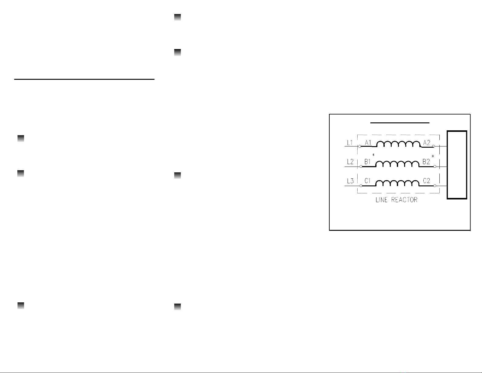
Below is the typical wiring diagram for the 3-phase
reactor applied to the front end of the Variable
Frequency Drive (VFD).
Single-phase applications are acceptable, howev-
er, it is important to size the unit based on the sin-
gle phase Full Load Amperage of the VFD. The
input and output connections should be on termi-
nals A and C to ensure proper performance.
Product Specifications
WiringDiagram
LOAD
LINE
*Forsingle-phaseapplications,usecoils
AandC.IsolateterminalsB1andB2.
u3-Phase, 600 Volt Class
uUL Recognized; File E-116124
uCE Marked
uCSA Approved
uCurrent rated device
u200% rated current for 3 minutes
uAmbient Temperature: 40° C
uPatented Bobbin Construction on
units smaller than 110 amps
uDistributed Gap Technology
TCI recommends that these reactors
be wired as close to the front end of the VFD
as possible.
In standard 40° C ambient or less
installations, a clearance of 3 inches on all
sides of the reactors and its enclosure is
recommended for assisting in heat
dissipation and ample wire bending space.
This is a general guideline for typical
applications. If the reactor is being installed
next to a heat sensitive instrument or control
device, we recommend reviewing specific
requirements or heat limitations. Line reac-
tor heat loss information is available in the
standard TCI product literature or on the web
at Trans-Coil website.
These reactors are designed to be
floor-mounted, or wall-mounted. Large
open-style devices should be panel
mounted by incorporating a bracket that
would act as a shelf to support the reactor
and/or enclosure. When installing an open
style device in an existing control cabinet,
drive cabinet, motor control center, or other
large enclosure, the reactor should be
mounted in the lower half of the cabinet to
prevent hot spots or pockets of heat.
Locating the reactor in the lower half of the
cabinet typically allows better thermal
dissipation and heat convection.
The KLR/KDR input line reactor
should be located as close to the drive as
possible to have the greatest success in
both protecting the VFD as well as mitigating
line harmonics. We recommend this be 10
feet of cable or less.
KLR/KDRLineReactor
InstallationInstruction
INPUT
RecommendationsandConsiderations
When installing the KLR/KDR Line Reactors
on the INPUT side of the Variable
Frequency Drive (VFD), please use the
following guidelines when wiring the unit:
The KLR/KDR Line Reactor is a 3-
phase device and should be wired in series
and positioned on the input side of the VFD.
All Terminal Block connectors will be
marked. A1, B1, and C1 are the input
terminals where the 3 phases of incoming
power are to be wired. As a result, A2, B2,
and C2 are the output terminals. Units with
copper bus or ring lug terminals are not
marked. In these cases, either the upper
terminals or the lower terminals can be used
as the input terminals, as long as the selec-
tion is consistent. For example, if an upper
terminal is selected as the input, all upper
terminals must be input terminals. Wiring
from the output terminals should connect to
the input of the VFD.
Refer to NEC wiring practices for
appropriate wire sizes for your application.
Buy: www.ValinOnline.com | Phone 844-385-3099 | Email: [email protected]

This manual suits for next models

1

Other TCi DC Drive manuals

TCi KLR Operating and maintenance instructions

TCi

TCi KLR Operating and maintenance instructions

Popular DC Drive manuals by other brands

PXM PX715-L0 user manual

PXM

PXM PX715-L0 user manual

PR electronics 9107 product manual

PR electronics

PR electronics 9107 product manual

Danfoss FC 302 instruction manual

Danfoss

Danfoss FC 302 instruction manual

Festo DFPI-***-***-ND2P-E-P-G2 operating instructions

Festo

Festo DFPI-***-***-ND2P-E-P-G2 operating instructions

Lenze L-force EYF A F04S06 Series Mounting instructions

Lenze

Lenze L-force EYF A F04S06 Series Mounting instructions

Parker HAS Series manual

Parker

Parker HAS Series manual

Fagor QC-PDS Hardware manual

Fagor

Fagor QC-PDS Hardware manual

Mitsubishi Electric FR-F500 Series instruction manual

Mitsubishi Electric

Mitsubishi Electric FR-F500 Series instruction manual

REED 5301PD Operator's manual

REED

REED 5301PD Operator's manual

Aerotech Automation1 iXC2 Hardware manual

Aerotech

Aerotech Automation1 iXC2 Hardware manual

BMG E3D V6 Assembly manual

BMG

BMG E3D V6 Assembly manual

Sourcetronic ST500 Series user manual

Sourcetronic

Sourcetronic ST500 Series user manual

Lenze L-force 8400 Series Mounting instructions

Lenze

Lenze L-force 8400 Series Mounting instructions

Erreka ERGOS Series Quick installation and programming guide

Erreka

Erreka ERGOS Series Quick installation and programming guide

Lenze L-force 8400 Series Mounting instructions

Lenze

Lenze L-force 8400 Series Mounting instructions

FALK Ultramite UB Installation & maintenance instructions

FALK

FALK Ultramite UB Installation & maintenance instructions

Danfoss AME 23 installation guide

Danfoss

Danfoss AME 23 installation guide

WEG MVW3000 Series user manual

WEG

WEG MVW3000 Series user manual

manuals.online logo
manuals.online logoBrands
  • About & Mission
  • Contact us
  • Privacy Policy
  • Terms and Conditions

Copyright 2025 Manuals.Online. All Rights Reserved.