manuals.online logo
Brands
  1. Home
  2. •
  3. Brands
  4. •
  5. Festo
  6. •
  7. DC Drive
  8. •
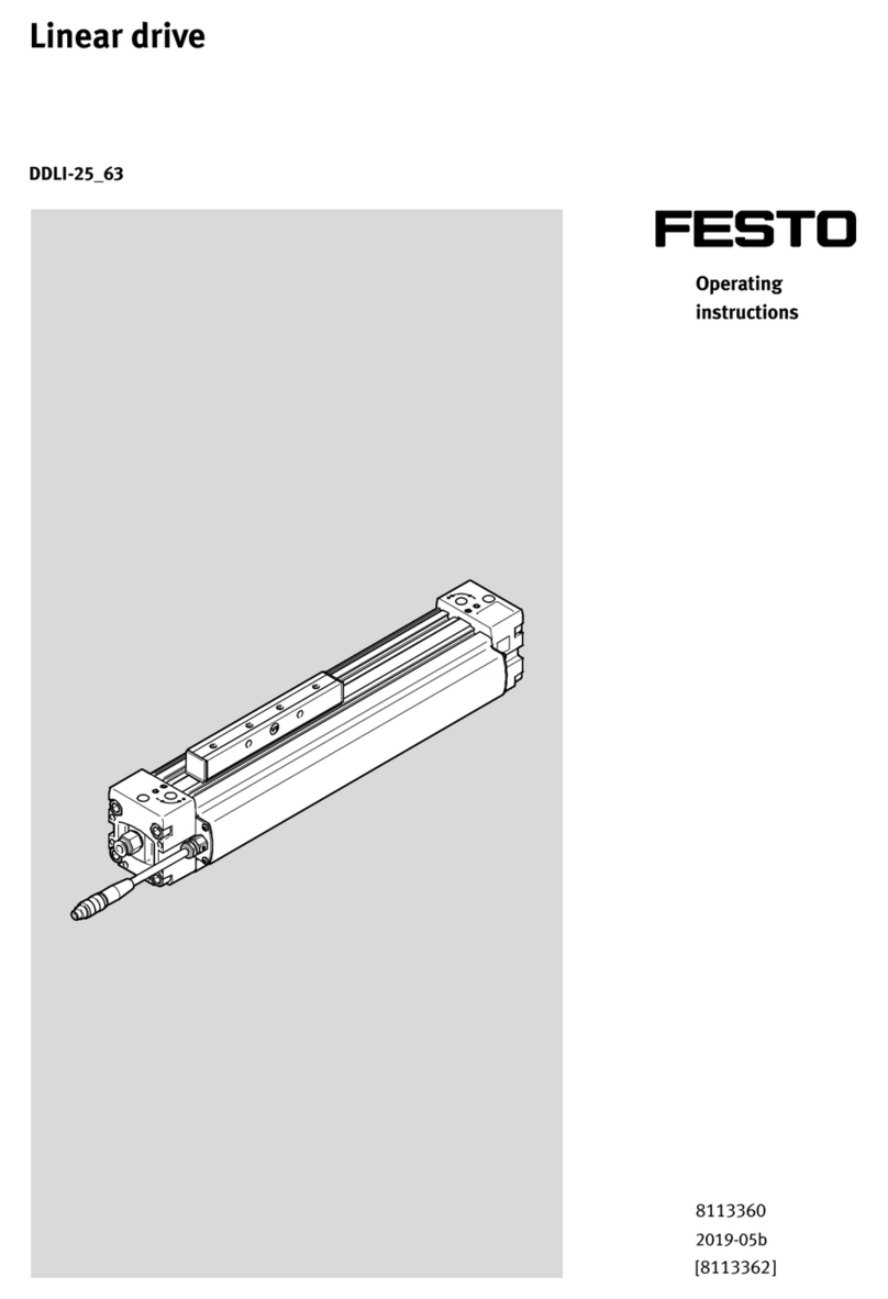
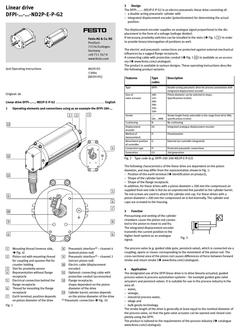
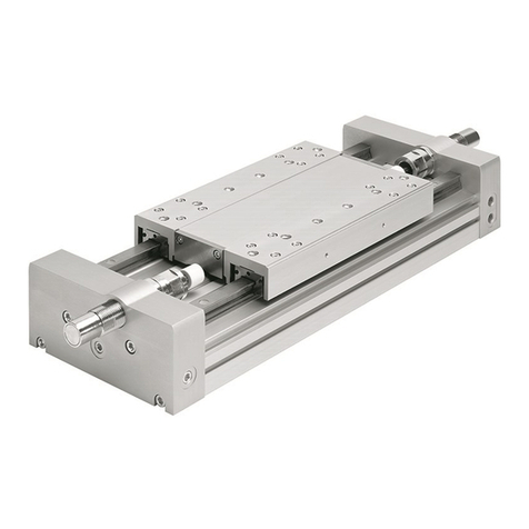
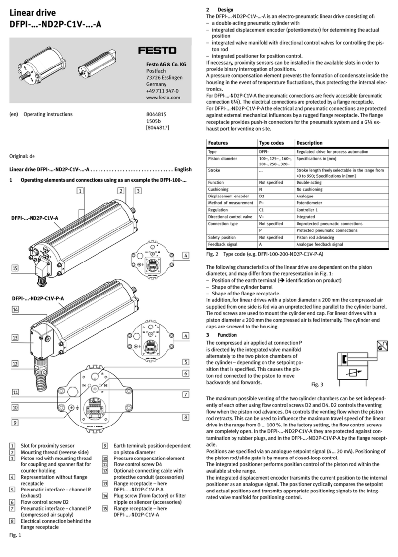
  9. Festo DSR-10-180-P User manual

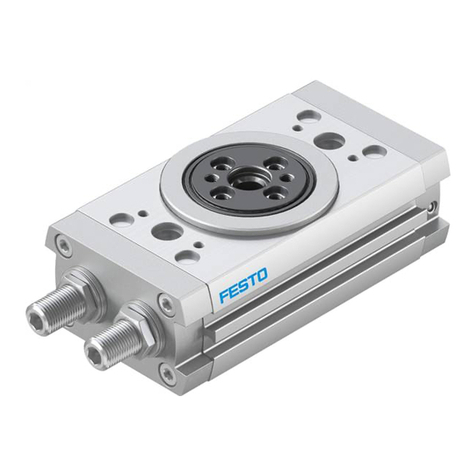
Festo DSR-10-180-P User manual

Operating
instructions
Pneumatic
rotary
drive
Type
DSR-
...
-P
Conditions regarcling the use of Festo
equipment.
This
is
important for reasons of safety
1.
lt'
is
most important that only properly instructed and
qualified personnel use this equipment.
2. This equipment should only be used within the limits
detailed
in
the
technical specification. Strict observance
of
the technical specification should be ensured at all times.
3. Correctly prepared compressed air should be used at
all times. When installing the equipment and thereafte
r,
the
Customershall ensurethatthe environmental conditions at
the place cf
use
are
taken
into
consideration. \
4.
lf
the equipment
is
incorporated
in
a system or used
within safety devices
or
circuits,the Customer shall ensure
that national and local safety laws and regulations are ob-
served
.
5. Should you require further information please contact
your local Feste office.
These instructions are important. Please keep
them
in
a safe place.
235 679
Bedienungsanleitung
Pneumatischer
Schwenkantrieb
Typ
DSR-
...
-P
Was ist beim Einsatz von Festo Elementen zu
beachten?
Die Einhaltung der jeweils angegebenen Grenzwerte für
Drücke, Geschwindigkeiten, Massen, Querkräfte, Tempe-
raturen und die Beachtung von Hinweisen ist Vorausset-
zung für die ordnungsgemäße Funktion und daher vom
Anwender unbedingt
zu
gewährleisten.
Es
ist aul d
en
Betrieb mit ordnungsgemäß aufbereiteter
Druckluft ohne aggressive Medien
zu
achten. Außerdem
sind die jeweiligen Umweltbedingungen
am
Einsatzort
zu
berücksichtigen.
Bei
An
wendung
von
Feste Elementen im Sicherheitsbe-
reich
sind
stets
auch
die jeweiligen
Vorschriften
der
Berufs
-
genossenschaft und des Technischen Überwachungs-
Vereins
bzw.
die entsprechenden nationalen Bestimmun-
gen
zu
beachten.
1.
Controls
/
connections
CD
Mark for adjustment
of
rotation angle
®Rotation-angle scale
@
Trip
cams for limit valves
©
Adjusting screws
to
limit angle
of
rotation
® Mounting holes
® Supply ports
2.
Technical
data
Part
No.
/Teile-Nr.
[)._
Type
/
Typ
0
~
0
.....
~
O>
'
C\J
a:
"'(/)
"'
Cl
[)._
0
CO
N
O>
'";-
0
a:
O>
.
(/)
::::::
Cl
1.
Bedienteile/
Anschlüsse
CD
Markierung für Drehwinkeleinstellung
®Drehwinkel-Skala
@ Schaltnocken tür Grenztaster
©
Einstellschrauben für Drehwinkelbegrenzung
®Befestigungsbohrungen
®Druckluft-Anschlüsse
2.
Technische
Daten
[)._
[)._ [)._
[)._
0 0 ö 0
CO
~
~
~
<k.
.;,
N
0
C\J
"'
.........
0'
~
d:
C\J
'
~
d:
~
a:
~
a:
O>
(/)
O>
(/)
O>
(/)
"'(/)
::::::
Cl
::::::
Cl
::::::
Cl
~
Cl
Medium Compressed air (filtered, lubricated or unlubricated) /
gefilterte, geölte oder gefilterte nicht geölte Druckluft
Design / Bauart Rotary cylinder with rotary vane /Drehzylinder mit Schwenkflügel
Temperature range /
-10
to
!
bis
+60
'C
Temperaturbereich
Operating pressure range /
2,5
to/
2
to/
bis
8
bar
1.5
to
8
bar/
1,5
bis
8
bar
Betriebsdruckbereich bis
8
bar
Mounting position / Einbaulage any / beliebig
Torque at
6
bar/
(Nm)
0,5 1 2 5 10
20
Drehmoment bei
6
bar
Permissible radial force
(N)
30 45 75 120 200
350
an
drive shaft / zul. Radial-
last aufAbtriebswelle
Permissible axial force an
(N)
10 18 30
50
75 120
drive shaft / zul. Axiallast
aufAbtriebswelle
Allowable mass (kgm
2)
0,2
x1
0-
4
0,
3x10
-
4
0,6 x10-• 0,9x10-
4
1
,4x
10-
4
2,0x10
-
4
moment
of
inertia
an
the
drive shaft /Zulässiges
Massenträgheitsmoment
auf derAbtriebswelle
3. Mounting
Mounting is by means
of
2 mounting holes.
Mounting holes Befestigungsbohrungen
Centering collar Zentrierbund
Correctly-centered rotary motion is ensured by a
centering collar on the housing.
Mounting can be carried out as desired eitherwith
or without additional mounting components.
3. Montage
Die Montage erfolgt über 2 Befestigungsbohrun-
gen.
Centering collar / Zentrierbund
Type/Typ
0D
DSR-10
20h8
DSR-12
22h8
D.SR-16
24h8
DSR-25 28h8
DSR-32
42
h8
DSR-40
52
h8
Durch einen Zentrierbund
am
Gehäuse ist eine mit-
tige Drehbewegung gewährleistet.
Die Montage erfolgt wahlweise mit oder ohne zu-
sätzliche Befestigungselemente.
Without additional mounting component,
by means
of
centering collar / With slip-on !lange /
mitAufsteckflansch With !lange mounting /
mit Flanschbefestigung
ohne Befestigungselement
Centering collarI
Zentrierbund
Foot mounting, optionally
top
or bottom fitting /
Fußbefestigung wahlweise oben und unten
Dowel pin /
Paßstift
orturned
through 180°,
top
or
bottom fitting /
180° gedreht, oben und unten
4.
Commissioning
The rotary drive is set in the factory for an angle
of
rotation
of
180°. The angle
of
rotation can be
changed
as
follows:
-Loosen the adjusting screw 0
1.
Set desired angle
of
rotation G).
2. Push the desired trip cam ®down
to
the stop.
3. Tighten the adjusting screw.
Warning:
The stops for the adjustment
of
the angle
of
ro-
tation are fitted with a bufferplate, and must not
be removed (this would lead
to
the destruction
of
the rotary vane).
Allen key sizes A/F and tightening torques
Type
/Typ
DSR-10
A/F size / Innensechskant SW
2,S
Tightening torques /
Anziehdrehmomente 1,
2Nm
4.2 Screw connectors into the suply ports ® (in-
ternal thread
MS).
-Connect tubing or hoses to the outputs
oi
the
power valve.
-Connect up the compressed-air supply.
-Reverse the valve.
-Check the angle of rotation, and, with pres-
sure switched oft, correct this if necessary.
4.
Inbetriebnahme
Schwenkantrieb ist ab Werk auf einen Drehwinkel
von 180° eingestellt.. Eine Änderung des Drehwin-
kels kann wie folgt vorgenommen werden:
-Einstellschraube @ lösen
1.
Gewünschten Drehwinkel G) einstellen
2. Schaltnocken ® bis zum Anschlag nach unten
schieben
3. Einstellschraube 0 anziehen
Warnung:
Die Anschläge für die Drehwinkeleinstellung
sind miteiner Pufferplatte versehen und dürfen
nicht entfernt werden (Zerstörung des
Schwenkflügels!).
Schlüsselweiten
SW
und Anziehdrehmomente
DSR-12 DSR-16 DSR-2S DSR-32 DSR-40
2,S
3 4 s 6
1,
2Nm
3,
0Nm
S,
9Nm
10Nm
2SNm
4.2 Verschraubungen
in
die Druckluft-Anschlüsse
® (Innengewinde
MS)
einschrauben.
-Rohre
bzw.
Schläuche mit den Ausgängen des
Arbeitsventils verbinden.
-Druckluft anlegen.
-Ventil umschalten.
-Drehwinkel kontrollieren, bei drucklosem Zu-
stand evtl. nachstellen.
©Supply
ports M3;
MS
and G
Va
/©Druckluft-Anschlüsse
M3;
MS
und
G1/a
5.
Mounting
of
limit
valves
a)
Micro stem-actuated valve and roller-lever valve
-Bott a mounting bracket to the rotary drive.
-Apply pressure
to
the rotary drive to bring it into
the end position to be set.
-Bott the limit valve hand-tight onto the mounting
bracket (do not tighten fully).
-Apply pressure to the limit valves.
-Push the limit valve upward until it is actuated.
-Tighten the mounting screws.
Please
note:
In
orderto prevent damagetothelimit valve,the
switching point must not be closer than 1 mm
from the housing
5.
Anbau
von
Grenztastern
a)
Mikro-Stößelventil und Rollenhebelventil
-Anbauwinkel am Schwenkantrieb anschrauben
-Schwenkantrieb mit Druck beaufschlagen, so
daß er
in
die einzustellende Endlage fährt.
-Grenztaster von Hand auf den Befestigungswin-
kel
schrauben (noch nicht festziehen)
-Grenztaster mit Druck beaufschlagen
-und nach oben schieben, bis er durchschaltet
-Befestigungsschrauben anziehen
Hinweis:
Um
Beschädigungen
zu
vermeiden, darf der
Schaltnocken das Gehäuse des Grenztasters
nicht berühren.
Abstand von mindestens 1 mm einhalten!
Adelalde ·
Ath«l
·Auckland ·
Barcelona·
Bangkok ·
Sek>
Horizonte · 61nningt*'1 ·
Bologns
· Botdellux ·
Brisbane
·
Bruxelles
·
~
·
BulrlosAlrn
·
Campinu
· Ce.P9Town
Cel
je·
Drllfl
·
Oub
H
11
·
Duncanvi
lle
·Dulban·
E
i
bar·Elndhoven
·
Arenze
·
Fukurol
·
G6teborg·Graz
·
Guadala
]
1WB
·
Helslnld
·
HongKong
·
l
si.nbu
l·
~
·
J
oi
n
vll
le
·
Johatlnest:MMg
l<alto
.
K#'lskrona .
~1'1811n
.
Kuala
Lumpur
·
l.eeds.
Lille
.
Lima
·
lliboa
. Loeamo ·
londol'1
·
4'on
.
Madrid. Malmö.
Manila
.
Melboume .
Meltleo
City .
Mllano .
Montenwy
~-Clty
·
Nalltes
·
Oslo
·
Padow.
·
P
aris
•
Perth
-
Pol'tEliubeltl
·
Porto
·
~WHh
ington·
PortoAl9gr9
·
Pl-aha·Pmofi-.·Pu.rtoRlco
·
Ouito
·
Reildai.'Ont.rlo
·
Rlode
..r.ntiiro
·
Roma
·
SatlJOS0
·
5aOPaulo·~
·
Seoul
·
Singa?CQ
·
5on.
·
S1ocldloln'l
·
Sydney
·
Talpel·Tehwan·Tokyo
·
Yalencla
·
W11t'1
1
2aW11
·
W
ien·
Yverdon
·
ZOrlch
FE
STD
PNEUMATIC
b)
Mounting of inducti
ve
proximity switches
-Bolt a mounting bracket
to
the rotary drive.
-Apply pressure
to
the rotary drive to bring it into
the end position
to
be set.
-Loosen the top nut ofthe proximity switch.
-
Fi
xthe proximity switch into position. Setthe dis-
tance between this and the trip cam to 0.3 mm.
Ple
a
se
Note:
The minimum distance must not be less than
0.1
mm
(danger ofdamage).
The maximum distance must not exceed
0.
7 mm (reliability ofswitching function).
6.
Operation
In
order to prevent damage
to
the rotary drive, the
maximum permissible mass moments of inertia
must not be exceeded.
lf
necessary, additional cushioning devices must
not be fitted (shock absorbers or dampers). Exter-
nally-mounted stopsmust notbe positioned at less
than the given minimum radius relati
ve
to the drive
shaft. '
b)Anbau von indukti
ven
Näherungsschaltern
-Anbauwinkel am Drehantrieb anschrauben
-Schwenkantrieb mit Druck beaufschlagen, so
daß
er
in
die einzustellende Endlage fährt
-obere Mutter des Näherungsschalters lösen
-Näherungsschalter anschrauben.
Den
Abstand
zum Schaltnocken auf 0,3 mm einstellen.
Hinweis:
Dermin.Abstand darf0,1mm nichtunterschrei-
ten (Zerstörungsgefahr).
D
er
max. Abstand sollte 0,7 mm nicht über-
schreiten (Sicherheit der Schaltfunktion).
6.
Betrieb
Die zulässigen Massenträgheitsmomente dürfen
nicht überschritten werden, um Zerstörungen am
Schwenkantrieb
zu
verhindern.
Gegebenenfalls müssen zusätzliche Dämp-
fungseinrichtungen angebracht werden
(S
i
oß
-
dämpfer oder Puffer). Extern angebrachte An-
schläge dürfen einen Mindestradius zur Antriebs-·
welle nicht unterschreiten.
Minimum radii for
external stop /
Mindestradien für
externe Anschläge
Type
/
Typ
DSR-10 DSR-12 DSR-16 DSR-25 DSR-32 DSR-40
Stop radius r min/
13mm
15mm
17mm
21
mm
28mm
40mm
Anschlagradius r
min
Max. impact 60 N
force / max.
Anschlagkraft
lt is also possible to
re
duce the speed to prevent
the mass moment of inertiafrom being exceeded.
In
order
to
reduce the angular velocity, one-way
flow control valves can be screwed into t
he
supply
ports.
7.
Maintenance
No maintenance is requi
red
.
Subject
to
change
FESTO
90 N
160
N 320 N 480 N
650N
Um
ein
Überschreiten des Massenträgheits-
moments zu verhindern, ka
nn
auch die Geschwin-
digkeit reduziert werden.
Zur Veränderung der Winkelgeschwindigkeit kön-
nen Drossel-Rückschlagventile
in
die Druckluftan-
schlüsse eingeschraubt werden.
7.
Wartung
Eine
Wartung ist nicht erforderlich.
Änderungen
vorbehalten
PNEUMATIC
Festo AG
&
Co. · Postfach · D-73726 Esslingen ·
"'"'
(0711)
347
-0 ·
lliJ
722 727
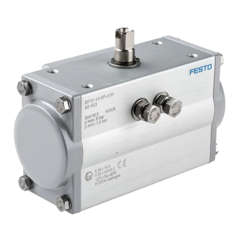
This manual suits for next models

5

Other Festo DC Drive manuals

Festo EMCS ST Series Reference guide

Festo

Festo EMCS ST Series Reference guide

Festo EMCA-EC-67 CO Series User manual

Festo

Festo EMCA-EC-67 CO Series User manual

Festo DNG Series Setup guide

Festo

Festo DNG Series Setup guide

Festo EMCA-EC-67 CO Series User manual

Festo

Festo EMCA-EC-67 CO Series User manual

Festo DNCE-***-LAS User manual

Festo

Festo DNCE-***-LAS User manual

Festo ERMO Series User manual

Festo

Festo ERMO Series User manual

Festo DRRD-12 User manual

Festo

Festo DRRD-12 User manual

Festo DRRD Series User manual

Festo

Festo DRRD Series User manual

Festo DFPD-Series User manual

Festo

Festo DFPD-Series User manual

Festo DSM-6 User manual

Festo

Festo DSM-6 User manual

Festo EMCA-EC-67-DIO Series Parts list manual

Festo

Festo EMCA-EC-67-DIO Series Parts list manual

Festo ERMS Parts list manual

Festo

Festo ERMS Parts list manual

Festo DGC Series User manual

Festo

Festo DGC Series User manual

Festo DGCI Series User manual

Festo

Festo DGCI Series User manual

Festo EMCS-ST User manual

Festo

Festo EMCS-ST User manual

Festo DGO-xxx-A-B series User manual

Festo

Festo DGO-xxx-A-B series User manual

Festo CMMT-AS-C2-11A-P3 S1 Series User manual

Festo

Festo CMMT-AS-C2-11A-P3 S1 Series User manual

Festo TP 1422 Operation instructions

Festo

Festo TP 1422 Operation instructions

Festo DAPS-...-R-...-F...-...-MW Series User manual

Festo

Festo DAPS-...-R-...-F...-...-MW Series User manual

Festo EMCS-ST User manual

Festo

Festo EMCS-ST User manual

Festo EMCA-EC-67 CO Series Operating and installation instructions

Festo

Festo EMCA-EC-67 CO Series Operating and installation instructions

Festo EMCS-YY-ST Reference guide

Festo

Festo EMCS-YY-ST Reference guide

Festo CMMT-ST-SW User manual

Festo

Festo CMMT-ST-SW User manual

Festo DGOL-16 PPV-A B Series User manual

Festo

Festo DGOL-16 PPV-A B Series User manual

Popular DC Drive manuals by other brands

Kinco CV100 Series manual

Kinco

Kinco CV100 Series manual

GFA ELEKTROMAT SI 260.9-80,00 installation instructions

GFA

GFA ELEKTROMAT SI 260.9-80,00 installation instructions

Erreka ERGOS Series Quick installation and programming guide

Erreka

Erreka ERGOS Series Quick installation and programming guide

elero RolMotion/D+ M-868 Operating and assembly instructions

elero

elero RolMotion/D+ M-868 Operating and assembly instructions

ABB ACS850 series Hardware manual

ABB

ABB ACS850 series Hardware manual

Eaton SC9000 EP installation manual

Eaton

Eaton SC9000 EP installation manual

YASKAWA CR700 Technical manual

YASKAWA

YASKAWA CR700 Technical manual

eldoLED POWERdrive 106/S Wiring diagram

eldoLED

eldoLED POWERdrive 106/S Wiring diagram

Eaton PowerXL DA1 installation manual

Eaton

Eaton PowerXL DA1 installation manual

eldoLED LINEARdrive 720D quick start guide

eldoLED

eldoLED LINEARdrive 720D quick start guide

ITOH DENKI POWER MOLLER HBM-604BN manual

ITOH DENKI

ITOH DENKI POWER MOLLER HBM-604BN manual

BONFIGLIOLI Vectron ACTIVE manual

BONFIGLIOLI Vectron

BONFIGLIOLI Vectron ACTIVE manual

Control Techniques Midi-Maestro user guide

Control Techniques

Control Techniques Midi-Maestro user guide

Zener MSC-3 manual

Zener

Zener MSC-3 manual

Sony DRV-1000 user guide

Sony

Sony DRV-1000 user guide

Danfoss VLT FC 103 operating instructions

Danfoss

Danfoss VLT FC 103 operating instructions

nord NORDAC SK 200E manual

nord

nord NORDAC SK 200E manual

Danaher Motion B8962 Operator's manual

Danaher Motion

Danaher Motion B8962 Operator's manual

manuals.online logo
manuals.online logoBrands
  • About & Mission
  • Contact us
  • Privacy Policy
  • Terms and Conditions

Copyright 2025 Manuals.Online. All Rights Reserved.