TCi ITT User manual

-
-
BASIC
INSTALLATION
AND
KEY
TELEPHONE SYSTEM
MANUAL
Performance Development Center ITT
TCI Library www.telephonecollectors.info

BASIC INSTALLATION
AND
KEY TELEPHONE SYSTEM
MANUAL
ISS
2,
PDC-AB-001
This manual
has
been
developed by the Performance Development Center.
It
is
intended
for
the
use
of
ITT
BCD
and their authorized distributor personnel only.
The information in this manual
is
subject
to
change.
While every
effort
has
been
made
to
eliminate errors, the company disclaims liability
for
difficulties arising from interpretation
of
the information contained herein.
Any
comments
or
suggestions
for
improving this manual would
be
appreciated. Forward
your remarks
to:
Manager
of
Documentation
ITT
BCD
Performance Development Center
Hwy. 45E at Kefauver Drive
Milan,
Tennessee
3B358
THIS
MATERIAL
CANNOTBE REPRODUCED WITHOUT THE EXPRESS
WRITTEN PERMISSION
OF
ITT-BCD.
LIMITED
DISTRIBUTION
ONLY
©
ITT
Telecommunications Corp.
TCI Library www.telephonecollectors.info

TCI Library www.telephonecollectors.info

CONTENTS SECTION
INTRODUCTION
•...••.•......•.••••
1
SPECIAL TOOLS
.•••......••••.•....
2
CABLE
AND
WIRING
............•..
3
AMP *50-PIN INSERTION TOOL
..•....
4
CONNECTING BLOCKS
.....••.......
5
FASTENERS, CABLE CLAMPS
AND
TIES
..••....•......•.•............
6
K-500 DESK TELEPHONE,
.......••...
7
K-500 TYPE
WALL
TELEPHONE
......•
8
K-510 DESK TELEPHONE
....•......•.
9
K-564/K-565 KEY TELEPHONE
.......
10
K-2500 DESK TELEPHONE
.....•...•.
11
K-2510 DESK TELEPHONE
..•••••.•.
12
K-2554
WALL
TELEPHONE
...•....••
13
K-2564/K-2565 KEY TELEPHONES
•...
14
TEN
AND
TWENTY BUTTON
KEY
TELEPHONES
•...•.....•...••.....
15
ISS
2, PDC-AB-001
CONTENTS SECTION
RINGERS
•••••..•..•••••..•..•.•••
16
REMOTE SIGNAL DEVICES
•••••••••.
17
DIALS
..•.•...•..••....•...••••.•.
18
NETWORKS
..•.••••••••..••••••...
19
DISTRIBUTING FRAME
•....••....••
20
TELEPHONE INSTRUMENT
MODIFICATIONS
....•.......•....•
21
BUTTONS
AND
BUZZERS
••••......•
22
LAMP ASSEMBLIES
.•••••.•.••••..•
23
TYPE 153A ADAPTER
....•.••••.•••
24
6040 KEY
••...••.•••..••••••••.•..
25
PC-4A SPEAKERPHONE
••.•.••...•••
26
K107A LOUDSPEAKER
.••••.••••.••
27
KEY SYSTEM EQUIPMENT
.•..•••..•
28
DIODE
MATRIX
.•.......•••.......
29
TCI Library www.telephonecollectors.info

TCI Library www.telephonecollectors.info

ISS
2, PDC-AB-001
1. INTRODUCTION
Purpose
of
Manual
1.01 The purpose
of
this manual
is
to
provide installation and main-
tenance personnel a technical reference
relating
to
the general installation and
maintenance
of
station apparatus and key
service equipment. Th
is
manual includes
information
on special tools; standard and
special station wire, cable, and hook-up wire;
wiring diagrams and descriptions
of
various
types
of
ITT
'station instruments, replace-
ment parts and auxiliary devices; and
MDF
and I
OF
organization and arrangement.
1.02 The
information
in this manual
is
general in nature and relates pri-
marily
to
those tasks (equipment mounting,
wiring, cabling, etc.) common
to
the in-
stallation
of
most single line telephones
and key system instruments. More de-
tailed
information
on installation, main-
tenance, and
modification
of
key system
equipment and individual PABX systems
will
be
found in
other
manuals and in the
applicable manufacturer's documents and
drawings.
1-1
TCI Library www.telephonecollectors.info

TCI Library www.telephonecollectors.info
ISS
2,
PDC-AB-001
2. SPECIAL TOOLS
CONTENTS
PAGE
Connecting Tool
.......
. .
....
......
2-1
Push
Drill
........................
2-2
Installer's Test Set.
.................
2-4
Type
140A
Test Set
................
2-5
Staplers
........
..
.............
.
..
2-6
2.01
Some
of
the
special
tools
in
the
in-
staller's
A-1
tool kit are described
in this section. Instructions
for
using
the
tools
are included.
Connecting Tool
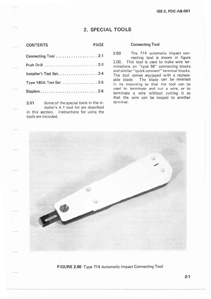
2.02
The
714
automatic
im
pact
con-
necting
tool
is
shown in figure
2.00.
This
tool
is
used
to
make wire
ter
-
minations
on
"type
66"
connecting blocks
and
similar
"quick-connect"
terminal blocks.
The
tool comes equipped with a replace-
able blade.
The
blade can
be
reversed
in i
ts
mounting so
that
the
tool can
be
used -
to
terminate
and
cut
a wire,
or
to
terminate
a wire
without
cutti
ng it so
that
the
wire can
be
looped
to
another
terminal.
FIGURE
2.00
Type
714
Automatic
Impact
Connecting
Tool
2-1
TCI Library www.telephonecollectors.info

ISS
2,
PDC
-AB-001
2.03
To
terminate and
cut
a wire,
a.
b.
Place the wire
in
the
fanning strip
and loop it over the hook
in
the
terminal.
Place
the
connecting tool on
the
term
in
al
with
the
cutting edge
of
the
blade up or down depending
on the location
of
the
wire
to
be
cut
off. See figure 2.01 .
FIGURE
2.01
"Punching
Down"
Wire
c. Push
the
tool against
the
terminal
until it cuts
off
the
excess wire.
2-2
NOTE: On some tools,
the
force
of
of
impact
is
controlled by an adjust-
ment
screw
in
the
handle
of
the
tool.
It can be adjusted
to
compensate for
too
little
or
too
much pressure. A
pointer
at
the
large end
of
the
handle
indicates
the
amount
of
pressure ap-
plied.
2.04
To
terminate a wire
without
cut-
ting it,
a.
b.
Loosen
the
screw
in
the
small
end
of
the
connecting
tool,
ro-
tate
the
blade
to
expose
the
op-
posite end, then retighten the
screw. See figure 2.02.
Place
the
wire
in
the
fanning strip
and loop it over
the
hook
in
the
termin~I
c. Place
the
connecting tool on
the
terminal.
d. Push
the
tool against
the
terminal.
The
connecting tool will
auto
-
matically ·trigger, resulting
in
a
precise termination.
Push Drill
2.05
The
Push Drill
is
shown
in
figure
2.03. It
is
an automatic push drill
and comes· equipped with bits capable
of
drilling wood
or
light metal.
The
handle
is
a holder for 10 bits.
To
insert a bit, proceed as follows:
a.
b.
Loosen
the
magazine locking nut,
remove
the
bit and close and secure
the
magazine.
Slide
the
chuck sleeve forward and
insert
the
bit
; release
the
chuck
to
the
normal position.
c.
The
drill
is
now ready for use.
The
drill being pushed will create a ro-
tary
action.
CAUTION: Keep both hands behind
the
drill
point
during operation.
Don't
hold any
equipment
in
your
hands dur-
ing
operation.
TCI Library www.telephonecollectors.info

ISS
2,
PDC-AB-001
BLADE IN "TERMINATE ANO
CUT"
POSITION BLADE
IN
"TERMINATE
ONLY"
POSITION
FIGURE 2.
02
Changing The Cutting Blade
FIGURE 2.
03
Push D
rill
2-3
TCI Library www.telephonecollectors.info
!
SS
2, PDC-AB-001
Installer's Test
Set
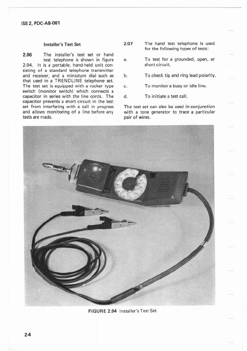
2.06 The installer's test set
or
hand
test telephone
is
shown
in
figure
2.
04
. It
is
a portable, hand-held unit con-
s1st1ng
of
a standard telephone transmitter
and receiver, and a miniature dial such as
that
used
in
a TRENDLINE telephone set.
The
test set
is
equipped with a rocker
type
switch (monitor switch) which connects a
capacitor
in
series with
the
line cords.
The
capacitor prevents a short circuit
in
the
test
set from interfering with a call
in
progress
and allows monitoring
of
a line before any
tests are made.
2.07
The
hand
test
telephone
is
used
for
the
following
types
of
tests:
a.
To
test for a grounded, open,
or
short
circuit.
b.
To
check tip and ring lead polarity.
c.
To
monitor
a busy
or
idle line.
d.
To
initiate a
test
call.
The
test
set
can also be used in conjunction
with a
tone
generator
to
trace a particular
pair
of
wires.
FIGURE
2.04 Installer's
Test
Set
2-4
TCI Library www.telephonecollectors.info

2.08
a.
b.
Use
the
installer's test set
as
follows:
Tip and Ring lead identification.
To
identify
the
tip
or
ring side
of
a line, turn
the
monitor switch
off
and connect one
of
the
test leads
to
ground. Then, listen
to
the
test
set receiver and momentarily
touch the
other
test lead
to
the
first connecting block terminal
and then
to
the
second connecting
block terminal. The terminal
touched when
the
loudest
"click"
is
heard,
is
the
ring side of
the
line. The ring terminal should be
the
right hand terminal on a hori-
zontal block
or
the
lower term
in
al
on a vertical block.
Grounded circuit test. To test for
a grounded circuit, open both
sides
of
the line
at
the
connecting
block terminal and connect one
test lead
to
a known source of
battery such
as
the
ring side
of
a
working line. While listening
to
the
test receiver, momentarily
touch
the
other
test lead first
to
one
Ii
ne lead and then
to
the
other.
If
a "click"
is
heard on
either wire, a ground
is
present.
c.
Short
circuit test. To test for a
short circuit, open one side
of
the
line only, and connect one test
clip
to
the
terminal-from which
the
wire was removed. While
listening
to
the
test receiver,
momentarily touch
the
other
test
clip
to
the
loose wire.
If
a "click"
is
heard, a short circuit
is
in-
dicated.
d. Open circuit test. To test for an
open circuit, connect
the
test clips
across
the
terminal lugs
at
various
connecting blocks on which
the
line appears, while listening
to
the
receiver. The open circuit
is
in-
dicated when a "click"
is
heard
at
one set
of
terminals and noth-
ing
is
heard
at
the
next test
point.
ISS
2, PDC-AB-001
e.
Crossed battery test. To test for
crossed battery, open both sides
of
the
line
at
the
connecting block
and connect one test clip
to
a
known ground. While listening
to
the
test receiver, momentarily
touch
the
other
test clip
to
one
Iine lead and then
to
the
other. If
a "click"
is
heard, it
is
an
in-
dication
that
a foreign source
of
battery
is
present.
Type 140A Test
Set
2.09 The model 140A test set
is
a
battery operated,
tone
generator
used
to
perform continuity tests and
to
locate broken wires
or
open pairs. It
is
powered by a 9 volt battery such
as
a 216
Eveready, VS323
RCA
,
or
a 006P import.
The test set generates two distinct audio
signals; an alternating 500/1000
Hz
tone
or
a continous 1000
Hz
tone. The test set
is
shown
in
figure 2.05.
FIGURE
2.05
Type 140A Test
Set
2-5
TCI Library www.telephonecollectors.info

ISS
2,
PDC-AB-001
2.10 An external switch on the unit
permits the user
to
turn the test
set on
or
off and
to
arrange it for a tone
output
or for continuity testing. An internal
switch permits operation
as
a continous
or
alternating tone source.
2.11 Procedures for using the 140A test
set are outlined
in
the following
paragraphs.
a.
b.
c.
2-6
Locating broken pairs. To locate
a broken pair,
1.
Place the external switch
in
the
TONE position.
2. Connect the red and black
test leads
to
the pair.
3.
Use
the installer's test set
to
probe for the pair with tone
present.
Continuity testing.
To
test
a
circuit for
an
open or short,
1. Place
the
external switch
in
the CONT position.
2. Connect the test set leads
to
the
desired leads. The
LED
on the test set lights
to
indicate a short, it remains
extinguished
to
indicate an
open.
Tip and ring identification. To
identify the ring side
of
a line,
1. Place the external switch
in
the
OFF position.
2. Connect the black test lead
to
ground.
3. Probe both sides
of
the line
with
the
red test clip. The
LED
on the test set lights
when the red clip
is
con-
nected
to
the
ring lead.
d.
NOTES:
1.
Test c
will
only work when
48
volt battery
is
on
the
line.
2.
If
no ground
is
available, con-
nect both leads
to
the wire pair.
If indicator does not light,
re-
verse the leads.
Line verification. The test set can
be used
as
follows for line verifi-
cation.
1.
Make a call
to
the line
to
be
tested.
Do
not
answer
the
call.
2. When the line
is
ringing, con-
nect the red test set lead
to
the
ring side of the line, con-
nect the black test lead
to
the
tip side of the line. The
LED
on the test set will light
each time ringing current
is
applied
to
the line.
3. To positively identify the
line, move the test set switch
from the OFF position
to
the
CONT position,
to
trip the
ring.
If
ringing ceases, the
line
is
positively identified.
Staplers
2.12 Two types of staplers are com-
monly used for installation work;
they are
the
T-25 and
the
T-75 staplers,
shown
in
figure 2.06. They are used
to
attach station wire
or
cable
to
wood sur-
faces.
a.
T-25 Stapler. The T-25 stapler
is
used
to
fasten 4 conductor station
wire. It uses
1/4
inch wide staples
3/8
inches or 7
/16
inches long.
TCI Library www.telephonecollectors.info

b.
ISS
2,
PDC-AB-001
FIGURE 2.06 Staplers
T-75 Stapler. The T-75 stapler
1s
used
to
fasten station cable. It
uses 1/2 inch wide staples,
5/8
or
7/8 inches long.
I.
DI
ST
ANCE
W
IRE
1 STAPLER LENGTH
NOTE: When fastening station wire or
cable, staples should be placed the
length
of
the stapler (about 7 inches)
apart. See figure 2.07.
FIGURE 2.07 Using The
Staple
~
2-7
TCI Library www.telephonecollectors.info

TCI Library www.telephonecollectors.info
ISS
2,
PDC-AB-001
3. CABLE AND WIRING
CONTENTS PAGE
Definitions
.......................
3-1
Color
Codes
.......................
3-1
Ordering Information
...............
3-2
Connectorized Cable
................
3-3
3.01
Some
useful cable
and
wire infor-
mation
is
provided in the follow-
ing
paragraphs. Types
of
cable
and
wire
are
described,
and
cable
and
wire color codes
and
ordering information
are
provided.
Definitions
3.02 The following definitions apply
to
the
use
of
various types
of
cable
and
wire.
a.
Feeder - A feeder cable
is
a large
cable leaving a central office
to
serve
a PABX
or
key system.
b.
Riser - A riser cable
is
one which
runs in a vertical direction in a
large building
or
on a pole.
c.
Station cable -The term station
cable refers
to
the cable which
extends from a wall outlet,
connecting block, etc.
to
a
multi-
1ine telephone
set.
d. Station wire -The term station
wire refers
to
the wire which ex-
tends from a wall outlet, con-
necting block, etc.
to
a single
line telephone
set.
e.
f.
Plug ended cable - A plug ended
cable
is
one having a male con-
nector attached
to
one end.
Connector-ended cable -A con-
nector-ended cable
is
one having
a female connector attached
to
one end.
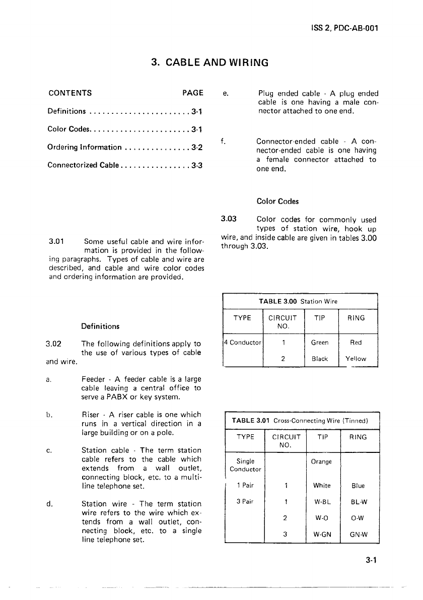
Color
Codes
3.03
Color
codes
for
commonly
used
types
of
station wire, hook up
wire,
and
inside cable
are
given in tables 3.00
through 3.03.
TABLE
3.00 Station Wire
TYPE
CIRCUIT
TIP RING
NO.
4 Conductor 1 Green
Red
2 Black Yellow
-
TABLE
3.01 Cross-Connecting Wire (Tinned)
TYPE
CIRCUIT
TIP RING
NO.
Single Orange
Conductor
1 Pair 1 White Blue
3 Pair 1 W-BL BL-W
2 W-0
0-W
3
W-GN
GN-W
3-1
TCI Library www.telephonecollectors.info

ISS
2, PDC-AB-001
TABLE
3.02 Inside Wire Cable
TYPE
CIRCUIT
TIP RING
NO.
6 Pair 1 W-BL BL-W
2 W-0
0-W
3
W-GN
GN-W
4
W-BN
BN-W
5 W-SL SL-W
6 R-BL BL-R
8 Pair 1 W-BL BL-W
2 W-0 0-W
3
W-GN
GN-W
4
W-BN
BN-W
5 W-SL SL-W
6 R-BL BL-R
7
R-0
0-R
8 R-GN GN-R
12 Pair 1 W-BL BL-W
2 W-0 0-W
3
W-GN
GN-W
4
W-BN
BN-W
5 W-SL SL-W
6 R-BL BL-R
7
R-0
0-R
8 R-GN GN-R
9 R-BN BN-R
10 R-SL SL-R
11
BK-BL BL-BK
12
BK-0
0-BK
TABLE
3.03 Inside Wire Cable
TYPE
CIRCUIT
TIP
RING BINDER
NO.
25 Pair 1 W-BL BL-W
2 W-0 0-W
3 W-GN GN-W
4
W-BN
BN-W
5 W-SL SL-W
6 R-BL BL-R
7
R-0
0-R
8 R-GN GN-R
9 R-BN BN-R
10 R-SL SL-R BL-W
11
BK-BL
BL-BK
12
BK-0
0-BK
13 BK-GN GN-BK
14 BK-BN BN-BK
15 BK-SL SL-BK
16
Y-BL
BL-Y
17
Y-0
0-Y
3-2
/,
iii
TABLE
3.03 Inside Wire
Cable
(Cont.)
TYPE
CIRCUIT
TIP RING BINDER
NO.
18 Y-GN GN-Y
19 Y-BN BN-Y
20 Y-SL SL-Y
21
V-BL BL-V BL-W
22
V-0
0-V
23 V-GN GN-V
24 V-BN BN-V
25 V-SL SL-V
50 Pair -26-50 Repeat first 25 0-W
colors
75 Pair -51-75 Repeat
first
25
GN-W
colors
100 Pair -75-100 Repeat
first
25
BN-W
colors
Ordering Information
3.04 Table 3.04 provides ordering in-
formation
for
commonly
used
cable and wire.
TABLE
3.04 Cable and Wire Ordering Information
STOCK NUMBER DESCRIPTION
. Single Tinned Wire
31163-00 1-Pair Cross-Connect Wire
31213-00 3-Pair Cross-Connect Wire
31165-00 2-Pair Station Wire
31001-00 6-Pair Inside
Cable
. 8-Pair Inside Cable
31004-00 12-Pair Inside Cable
31005-00 25-Pair Inside Cable
31006-00 50-Pair Inside Cable
31007-00 75-Pair Inside Cable
31008-00 100-Pair Inside Cable
*Denotes no stock number, item
not
stocked.
TCI Library www.telephonecollectors.info
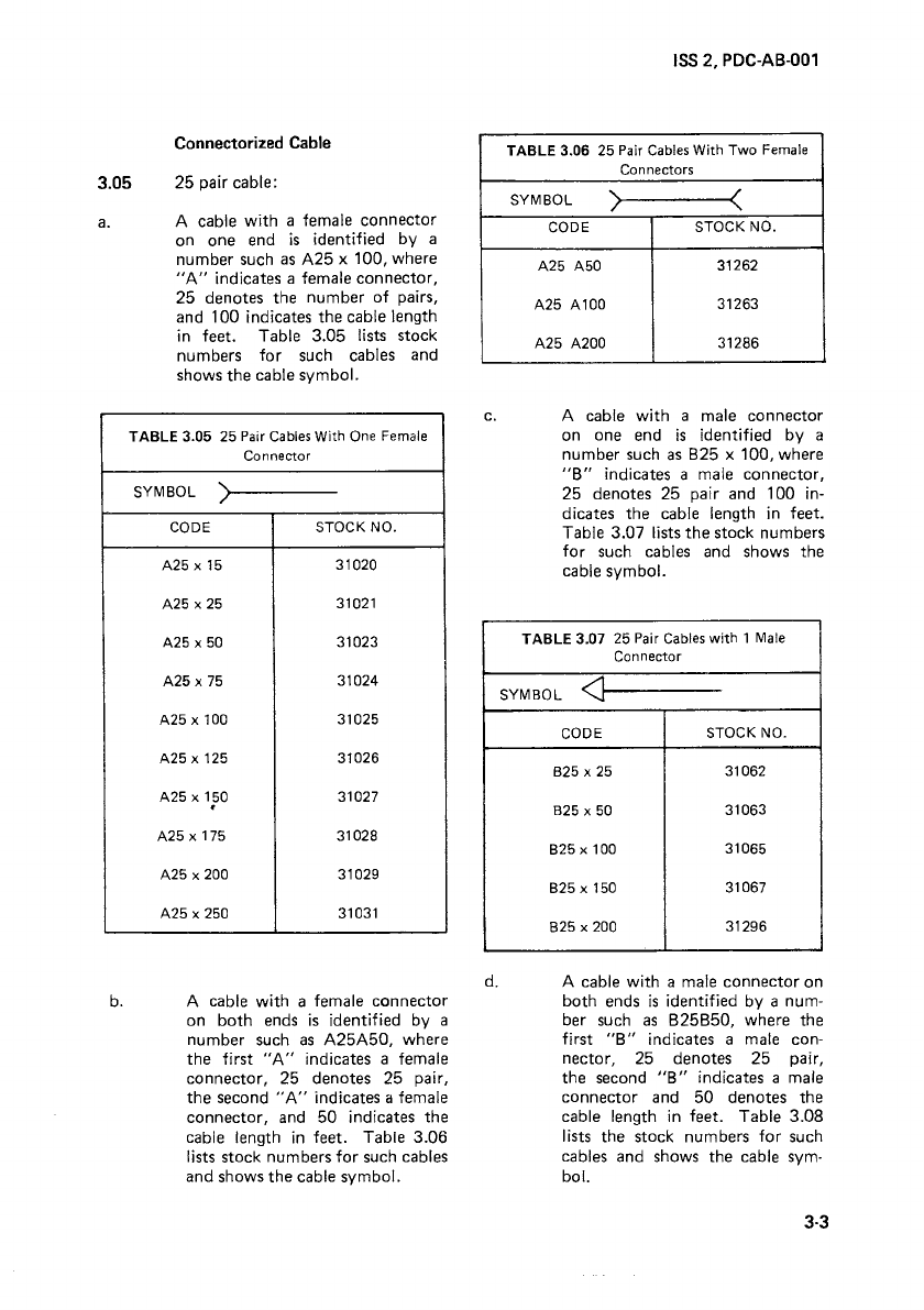
Connectorized Cable
3.05 25 pair cable:
a.
A cable with a female connector
on one end
is
identified by a
number such as A25 x 100, where
"A"
indicates a female connector,
25 denotes the number of pairs,
and 100 indicates the cable length
in
feet. Table 3.05 lists stock
numbers for such cables and
shows the cable symbol.
b.
TABLE 3.05 25 Pair
Cables
With
One
Female
Connector
SYMBOL '
/
CODE
STOCK NO.
A25 x
15
31020
A25 x 25 31021
A25 x 50 31023
A25 x 75 31024
A25 x 100 31025
A25 x 125 31026
A25 x 150 31027
•
A25 x 175 31028
A25 x 200 31029
A25 x 250 31031
A cable with a female connector
on both ends
is
identified by a
number such
as
A25A50, where
the first
"A"
indicates a female
connector, 25 denotes 25 pair,
the second
"A"
indicates a female
connector, and 50 indicates the
cable length
in
feet. Table 3.06
lists stock numbers for such cables
and shows the cable symbol.
ISS
2, PDC·AB-001
TABLE
3.06 25 Pair
Cables
With Two
Female
Connectors
SYMBOL ) <
CODE STOCK NO.
A25 A50 31262
A25 A100 31263
A25 A200 31286
c. A cable with a male connector
on one end
is
identified by a
number such
as
825
x 100, where
"8"
indicates a male connector,
25 denotes 25 pair and 100
in-
dicates the cable length
in
feet.
Table 3.07 lists the stock numbers
for such cables and shows the
cable symbol.
d.
TABLE 3.07 25 Pair
Cables
with
1
Male
Connector
SYMBOL
<]
CODE STOCK NO.
B25 x 25 31062
B25 x 50 31063
B25 x 100 31065
B25 x 150 31067
B25 x 200 31296
A cable with a male connector on
both ends
is
identified by a num-
ber such
as
825850,
where the
first
"8"
indicates a male con-
nector, 25 denotes 25 pair,
the second
"8"
indicates a male
connector and
50
denotes the
cable length
in
feet. Table 3.08
lists the stock numbers for such
cables and shows the cable sym-
bol.
3-3
TCI Library www.telephonecollectors.info

ISS
2, PDC-AB-001
TABLE
3.08 25
Pair
Cables
With 2
Male
Connectors
' SYMBOL
<}---[>
CODE STOCK NO.
B25 825 31264
825 850 31265
825 B100 31266
e.
A cable with a male connector on
one end and female on
the
other
end
is
identified by a number
such
as
A25B25, where
"A"
in-
dicates a female connector, 25
denotes 25 pair,
"B"
indicates
a male connector, and 25 denotes
the
cable length
in
feet. Table
3.09 lists
the
stock numbers for
such cables and shows
the
cable
symbol.
TABLE
3.09 25 Pair
Cables
With 1 Male
and
1 Female Connector
SYMBOL >
C>
CODE STOCK NO.
A25 B25 31106
A25 B50 31108
A25 B75 31109
A25 B100 31110
A25 B150 31112
A25 B175 31113
A25 8200 31114
3-4
3.06 50 pair cables.
a.
A cable with
two
female con-
nectors on one end
is
identified by
a number such
as
A50 x 25 where
"A"
indicates a female connector,
50
denotes
the
number of pairs,
and 25 indicates
the
cable length
in
feet. Table 3.10 lists
the
stock
numbers for such cables and
shows
the
cable symbol.
TABLE
3.10 50
Pair
Cables
With 2
Female
Connectors
SYMBOL
~
CODE STOCK NO.
A50
x 25 31034
A50 x 50 31035
A50 x
75
31036
A50 x 100 31037
A50 x 200 31041
b. A cable with
two
female con-
nectors on one end and two male
connectors on
the
other
end
is
identified by a number such
as
A50
8250.
Table 3.11 lists stock
numbers for such cables and
shows
the
cable symbol.
TABLE
3.11 50
Pair
Cables
With 2
Female
and
2 Male Connectors
SYMBOL
~
CODE STOCK NO.
A50 825 31271
A50
850 31240
A50 8250 31237
TCI Library www.telephonecollectors.info

3.07 75 pair cables: A cable
with
three female connectors on one
end
is
identified by a number such
as
A75
x 50. Table 3.12 lists stock numbers
for
such cables and shows the cable symbol.
TABLE
3.12 75
Pair
Cables
With 3
Female
Connectors
SYMBOL
~
CODE STOCK NO.
A75 x 25 31044
A75 x
50
31045
A75 x
75
31046
A75 x 100 31047
A75 x 150 31049
A75 x 200 31051
ISS
2, PDC-AB-001
3.08 100 pair cables: A cable
with
5
female connectors at one end
is
identified
by
a number
such
as
A 100 x 100.
Table 3.13 lists stock numbers
for
such
cables and shows the cable symbol.
TABLE
3.13 100 Pair
Cables
With 5 Female
Connectors
SYMBOL
t-
CODE STOCK NO.
A100x
100 31233
A100 x 200 31234
3-5 •
TCI Library www.telephonecollectors.info
Table of contents
Popular Telephone System manuals by other brands

Siemens
Siemens HiPath 3000 SMGI Administrator's manual

CallerID
CallerID Vertex VoIP Caller ID manual

Talkswitch
Talkswitch CT.TS005.001101.UK user guide

Panasonic
Panasonic KX-TVS95 installation manual

Panasonic
Panasonic KX-TGP700 Installation

Nortel
Nortel Meridian Meridian 1 General maintenance information


digi-tech
digi-tech 7714S Series user guide

Black Box
Black Box Video Sentry Color Tilt Phone System brochure

Bicom Systems
Bicom Systems OfficeBox Gen. 3 Hardware manual

Aastra
Aastra Venture IP 480i installation guide

Teltone
Teltone TLS-5C user manual

Panasonic
Panasonic Easa-Phone KX-T3281W operating instructions