OfficeServ 7200 General Description Guide Table of Contents
© Samsung Business Communications Page VII
LIST OF FIGURES
Figure 1.1 Service Structure of the OfficeServ 7200 .................................................... 1-4
Figure 1.2 Interfaces between the SIP Components.................................................... 1-8
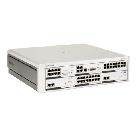
Figure 2.1 OfficeServ 7200 Chassis Configuration.......................................................2-3
Figure 2.2 Rear Panel of the OfficeServ 7200.............................................................. 2-4
Figure 2.3 Front View of the MCP.................................................................................2-7
Figure 2.4 Front View of the LCP..................................................................................2-8
Figure 2.5 Front View of the TEPRI............................................................................ 2-10
Figure 2.6 Front View of the 4BRI...............................................................................2-12
Figure 2.7 Front View of the 8TRK .............................................................................2-13
Figure 2.8 Front View of the 8SLI............................................................................... 2-14
Figure 2.9 Front View of the 16SLI (and 16MWSLI)................................................... 2-15
Figure 2.10 Front View of the 8DLI............................................................................... 2-16
Figure 2.11 Front View of the 16DLI.............................................................................2-17
Figure 2.12 Front View of the 8COMBO....................................................................... 2-18
Figure 2.13 Front View of the WIM............................................................................... 2-19
Figure 2.14 Front View of the LIM.................................................................................2-20
Figure 2.15 Front View of the 4DSL..............................................................................2-21
Figure 2.16 Front View of the MGI................................................................................ 2-22
Figure 2.17 Front View of the 4WLI..............................................................................2-24
Figure 2.18 Front View of the SVMi-20E ...................................................................... 2-25
Figure 2.19 WBS24.......................................................................................................2-33
Figure 2.20 WIP-5000M................................................................................................ 2-33
Figure 2.21 DS–4028D.................................................................................................2-27
Figure 2.22 DS-5012L...................................................................................................2-29
Figure 2.23 DS-5014D.................................................................................................. 2-33
Figure 2.24 DS-5021D.................................................................................................. 2-32
Figure 2.25 DS-5038D.................................................................................................. 2-32
Figure 2.26 ISDN Phone............................................................................................... 2-32
Figure 2.27 ITP-5012L.................................................................................................. 2-32
Figure 2.28 ITP-5014D .................................................................................................2-32
Figure 2.29 ITP-5021D .................................................................................................2-32
Figure 2.30 DS-5064B..................................................................................................2-32
Figure 2.31 DPIM.......................................................................................................... 2-32
Figure 2.32 KDB-D/S for DS Phones............................................................................2-35
Figure 2.33 KDB-D/S for Digital Phones.......................................................................2-32
Figure 2.34 WBS24.......................................................................................................2-33
Figure 2.35 WIP-5000M................................................................................................ 2-33
Figure 3.1 Trunk Line Loop Start Signalling.................................................................. 3-3
Figure 3.2 OfficeServ 7200 Chassis Configuration.....................................................3-12
