TCS CS-105 User manual

DRAFT
CS-105 DCC Command Station
& Booster Manual
Featuring
● 5 Amp Continuous DCC Track Output with User Adjustable Current Limit
● Supports 12V or 15V Power Supplies
● Soft Start Power Up Accommodating Multiple Sound Locomotives
● Short Circuit and Load Current Reporting
● 5 Status LEDs for Easy Status and Diagnostics
● LCC Features
○ CAN Data and Power Port
○ Plain English Configuration
○ WiFi and CAN Interfaces
○ Smart-phone, tablet, or PC WiFi enabled configuration
○ Up to 10 WiFi Throttles when using an external WiFi Access Point (Router)
○ Up to 4 WiFi Throttles in self hosted WiFi Access Point mode
○ Up to 250 Throttles through auxiliary LCC WiFi base stations
● Up to 62 Cab Bus (NCE, Ramtraxx, and SystemOne) Throttles and Accessories
● Up to 31 XpressNET (Lenz, Roco, ZTC, etc...) Throttles and Accessories
● Up to 260 Locomotives and Consists
● WiThrottle™ and Engine Driver through JMRI and WifiTrax WFD-30/31
● DCC Programing on the Main (with CV read-back via RailCom®)
● Global RailCom®Detector to Support Compatible Boosters
● Dedicated DCC Programming Track Output
● Märklin/Motorola protocol decoders also supported
● Software updateable by the User
Train Control Systems Phone (215) 453-9145
P.O. Box 341 Fax (215) 267-0735
Blooming Glen, PA 18911 Web www.tcsdcc.com
© 2022 Train Control Systems

DRAFT
Contents
1 Introduction 5
1.1 Specifications 5
1.2 Physical Overview 6
1.3 Status LEDs 7
2 Track Output 8
3 Throttle Support 9
3.1 WiFi 9
3.1.1 LCC 9
3.1.2 WiThrottle™ and Engine Driver 10
3.1.3 Autodiscovery 10
3.2 NCE, Ramtraxx, SystemOne Support 10
3.2.1 NCE Wireless 10
3.2.2 Main LCD Screen 11
3.2.3 Select Loco 12
3.2.4 Macro Button 13
3.2.5 Select Accessory 13
3.2.6 Locomotive Functions 14
3.2.7 Emergency Stop 14
3.2.8 Locomotive Names 14
3.2.9 Legacy Throttles 15
3.2.10 Unsupported NCE, Ramtraxx, and SystemOne Hardware 15
3.3 XpressNet™ Support 15
4 Locomotive and Consist Roster 16
4.1 Creating a New Roster Entry 16
4.1.1 Throttle Configuration 17
4.1.2 JMRI Configuration 17
4.2 Deleting an Existing Roster Entry 19
4.3 Function Configuration for Roster Entries 19
4.3.1 Function Names 19
4.3.2 Momentary Functions 19
4.4 Consist Settings 19
© 2022 Train Control Systems Page 2 of 49

DRAFT
4.4.1 Consist Behavior 19
4.4.2 Headlight MU switch 20
4.5 Special Features of Headlight (F0) 20
4.5.1 Directional Control 20
4.5.2 Blank F0 Forward/Reverse 21
5 Operating Trains 21
5.1 Speed and Function Operations 21
5.2 Consisting 21
5.3 Technical information 22
5.3.1 Status screen 22
5.3.2 Locomotive stack 22
5.3.3 Start-up behavior 23
5.3.4 Packet prioritization and repetition 23
5.3.5 RailCom®-enabled DCC decoders 23
5.3.6 Heartbeat 23
5.3.7 Speed mapping 23
6 DCC Decoder Programming 24
6.1 Mainline Programming 24
6.1.1 OPS mode programming with RailCom® 24
6.1.2 OPS mode programming without RailCom® 24
6.2 Programming Track Programming 25
6.2.1 Direct Mode Programming 25
6.2.2 Paged Mode Programming 25
6.3 DCC Address Programming 26
6.3.1 Short Address Programming 27
6.3.2 Long Address Programming 27
6.3.3 Consist Address (CV 19) Programming 28
7 Configuration 29
7.1 Factory Reset 29
7.2 Push Button Track Power On/Off 29
7.3 Push Button Configuration Mode 30
7.3.1 Secure AP Configuration Mode Entry 30
7.3.2 Open AP Configuration Mode Entry 30
© 2022 Train Control Systems Page 3 of 49

DRAFT
7.3.3 WiFi Client Mode 30
7.3.4 WPS Configuration Mode Entry 30
7.3.5 Remove All Custom WiFi Connection Profiles Mode Entry 31
7.3.6 Exit Push Button Configuration Mode 31
7.3.7 Push Button Flow Chart 32
7.4 WiFi Configuration 33
7.4.1 Web Server Based Configuration 33
7.4.2 TCS Throttle Based Configuration 34
7.4.3 JMRI Based Configuration 36
7.4.4 WPS Based Configuration 36
7.4.5 IP address changes 36
7.5 System Configuration 36
7.5.1 User Info Settings 36
7.5.2 System Settings 37
7.5.3 WiFi Settings 37
7.5.4 Macros 37
7.5.5 Status 37
7.6 Configuration Backup and Restore 37
8 LCC CAN bus 38
9 Updating the Software Version 38
9.1 Updating Through D.E.P.O.T. 38
9.2 Updating Through Web Interface 39
10 Troubleshooting Guide 41
10.1 Diagnostic LED Overview 41
10.1.1 Troubleshooting Steps 42
10.2 WiFi Performance 47
10.2.1 No External WiFi Access Point or Router Used 47
10.2.2 External WiFi Access Point or Router used 47
10.2.3 Mesh WiFi 47
11 Possible Trademarks to Acknowledge 49
© 2022 Train Control Systems Page 4 of 49

DRAFT
1 Introduction
The CS-105 is designed to be a next-generation NMRA DCC and Märklin/Motorola command station
featuring on-board WiFi with full support for NMRA LCC. An Auxiliary Cab Bus port is also provided which
can be used with some of the proprietary system buses of other manufacturers. The CS-105 has the
capacity to scale from small, to large, to huge model railroads.1
Shown above is an example of how the CS-105 can expand using other LCC devices, as well as how you
can seamlessly integrate existing devices from other manufacturers.
1.1 Specifications
● 5 Ampere maximum Continuous Current Rating (add-on Boosters Available)
● Up to 4 LCC WiFi Throttles via on-board WiFi Access Point
● Up to 62 Cab Bus (NCE, Ramtraxx™, and SystemOne™) Throttles and Accessories (via RJ-11)
● Up to 31 XpressNet™ (Lenz, Roco, ZTC, etc...) Throttles and Accessories (via RJ-11)
● One RailCom®detector
● One dual-RJ45 header for LCC Communication
● Support for LCC & DCC Data Transmission Over LCC
● 400mA output current capacity per LCC port
● Unlimited WiFi Throttle Connections Through Auxiliary LCC-enabled WiFi Base Station(s)
● Simultaneous running for up to 260 Locomotives and Consists
1Provides NMRA S-9.1.2 Full Scale Power Station (Booster) Interface output capable of supplying 400mA, enough to
support more than 30 TCS boosters.
© 2022 Train Control Systems Page 5 of 49

DRAFT
1.2 Physical Overview
The CS-105 features a case design which is symmetrical in nature, meaning that it can be mounted or
oriented in just about any way you could possibly need to, even vertically! TCS does advise against having
any obstruction on the vented sides of the case in order to allow for passive air flow, however. We will be
referring to these vented sides as Side A and Side B, since what the “back” and “front” are are up to you.
Side A features: 1) Single RJ-11 jack 2) Tactile push button 3) Single red LED.
Side B features: 1) Green 3-pin connector with detachable screw terminal 2) Black 2-pin connector with
detachable screw terminal 3) DC Power input jack 4) Dual RJ-45 LCC connector with four LEDs
The purpose of the LEDs is described in detail in the section below.
© 2022 Train Control Systems Page 6 of 49

DRAFT
1.3 Status LEDs
The CS-105 includes a total of five LEDs for providing information about the device’s status. The LEDs are
also used during configuration as described in the Push Button Configuration section. Additionally, both the
user and TCS support can use these LEDs in order to Troubleshoot issues.
On Side A of the CS-105 there is a single red Power LED. This LED is constantly on whenever the CS-105
has incoming power. On Side B, the dual RJ-45 LCC connector has the remaining four LEDs in a Yellow,
Green, Yellow, Green pattern as shown below:
Normal Operation
(From L to R)
CS
Booster
LED 1 - Yellow
closest to the barrel
jack
Track Power
- solid on: track power on
- solid off: track power off
- fast blink, short circuit
- slow blink: thermal overload
LED 2 - Green
CAN Active and LCC Activity
- solid on: CAN bus connected
- solid off: CAN bus disconnected
- blink: LCC activity (TX)
LED 3 - Yellow
WiFi Status
- blink: searching /
connecting
- constant off, AP mode
- constant on, client mode
Incoming DCC signal
- on DCC signal present
- off DCC signal absent
LED 4 - Green
WiFi/LCC Full - Either:
- 4 WiFi clients (on)
- 10 LCC sockets (on)
Identify LED
Press button in CDI - LED
comes on for 30 seconds
LED 4 - Green
(upon crash)
Blink Codes2
Bootloader
When the device is in Firmware Upgrade mode, LED 1 and LED 4 are alternately blinking like a grade
crossing. LED 2 (LCC) and LED 3 (WiFi) are operating as normal.
2Blink Codes are defined in detail in the Troubleshooting section of this guide
© 2022 Train Control Systems Page 7 of 49

DRAFT
2 Track Output3
The CS-105 track output can be driven from a wide range of voltages. The output voltage of the system to
the track will be the same as the input voltage. The output voltage of the system can be displayed at any
4
time from a TCS throttle as described in the Configuration section of this manual.
The built-in DCC booster of the CS-105 is designed for a continuous capacity of 5 Amps. This output is also
compatible with the Märklin/Motorola protocol, and both protocols can be in use at the same time. The
CS-105 may be used to power any scale, but it is important to ensure that you are capable of powering
your layout with the system. In some cases, one or more add-on devices such as the TCS B-106 Booster
may be necessary in order to supply some extra current capacity. Modern N and HO scale locomotive
motors are typically very efficient, even under load. Below, we have included a table for some examples of
typical load values which can help you determine if the CS-105 is capable of supplying your typical
operation by itself:
Locomotive Type
Typical Current Draw
Locomotive Max Count (Typical)
Idle/Stationary
0.05A - 0.10A
50 - 100
Idle/Stationary with sound
0.15A - 0.25A
20 - 33
N scale under load
0.15A - 0.35A
14 - 33
N scale under load with sound
0.30A - 0.50A
10 - 16
HO scale under load
0.25A - 0.50A
10 - 20
HO scale under load with sound
0.35A - 0.65A
7 - 14
Note that the values in the table above are very generalized. Your results will vary for your own
locomotives. Some older HO and N scale locomotives used much less efficient motors and can
subsequently draw more current. The built in booster has the ability to measure track current, and this
feature can be used to characterize a given locomotive for its typical current draw.
The built in booster is equipped with a soft-start mechanism to automatically limit the inrush current
symptomatic of older first generation sound decoders.
Additional external boosters may be added to the system for supplemental power, always be sure to include
the booster common shown in the diagram below (green wire):
4Output and Input Voltages will vary slightly due to negligible rectification and propagation losses.
3The terms “power station” and “booster” are used to refer to the track output(s) of the system as defined in NMRA
S-9.1 and are not in reference to external, add-on boosters unless otherwise specified.
© 2022 Train Control Systems Page 8 of 49

DRAFT
Shown above is a simplified diagram of how to wire the CS-105 into a LCC network with an additional
B-106
3 Throttle Support
3.1 WiFi
The CS-105 has built-in WiFi. The WiFi interface can be used for connecting different accessories including
LCC throttles, LCC accessories, gateways & repeaters, and computer software such as JMRI. The CS-105
WiFi has several limitations that may need to be considered.
Number of Simultaneous Connected Devices Supported
Limit
Access Point mode (default, not using an external Access Point or router)
4
Station mode (client to an external Access Point or router)
10
In order to simultaneously connect more than 10 LCC throttles over WiFi, auxiliary WiFi base stations (sold
separately) or a WiFi LCC repeater software running on a PC can be added in order to expand the number
of connected WiFi devices to 250.
The default WiFi Configuration for the CS-105 is as follows:
SSID:
Password:
Port Number:
Connect Mode:
LAYOUTWIFI
123456789
12021
LCC
Note: This configuration is programmed into TCS WiFi throttles such as the UWT-100 and UWT-50 by
default as the first profile. For more information about configuring the CS-105 WiFi modes, see the WiFi
Configuration section of this guide.
3.1.1 LCC
LCC Over WiFi
TCS Universal WiFi Throttles can be connected to the CS-105 by placing them on the same WiFi network
as either the CS-105 or an auxiliary WiFi base station. Once on the same network, a UWT will automatically
connect to the CS-105.5
5The default profile must not be overwritten or deleted and the default WiFi configuration of the CS-105 is unchanged.
© 2022 Train Control Systems Page 9 of 49

DRAFT
Wired LCC Throttles
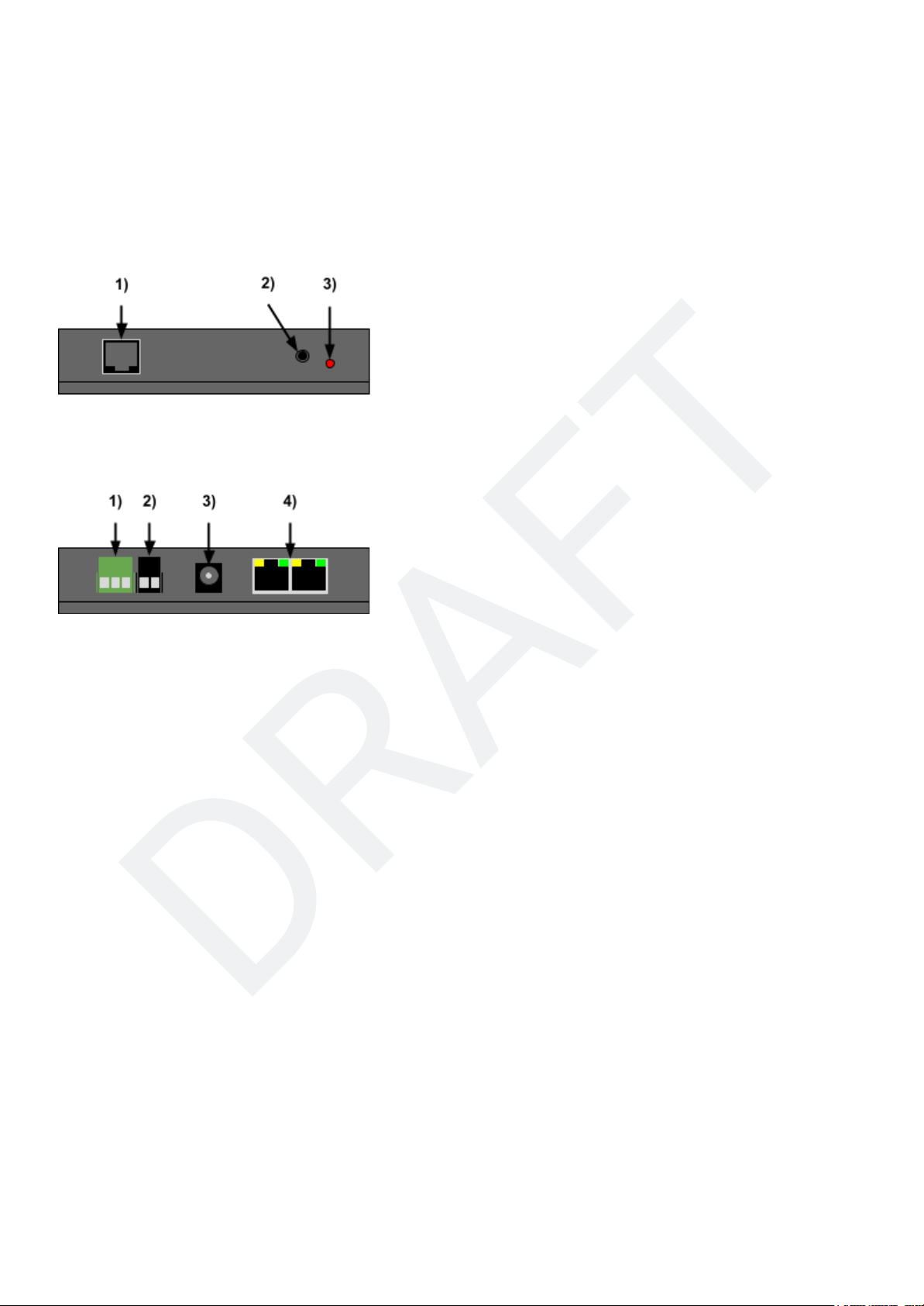
TCS T-50 wired throttles, and/or LT-50 handhelds can be connected directly to the CS-105 through the
on-board dual-RJ-45 LCC header, and/or through add-on LCC fascia panels also available from TCS. If you
connect a T-50 directly to the CS-105 without any other connections on the LCC bus, you must plug a LCC
terminator into the other open port.
Additional LCC throttles, including those controlled by a computer program such as JMRI, can be
connected to and operate trains on the CS-105 through the use of a LCC transceiver such as the LCC
Buffer-USB or LCC-LocoNet Gateway devices available from RR-CirKits Inc.
3.1.2 WiThrottle™ and Engine Driver
WiThrottle™ and Engine Driver throttles can be connected to the CS-105 by using the WiThrottle Protocol
server in JMRI or by using the WFD-30/31 modules from WiFiTrax connected through the Auxiliary
connector in NCE/Ramtraxx/SystemOne Cab Bus mode.
3.1.3 Autodiscovery
The CS-105 uses a standard protocol called mDNS in order for throttles to automatically connect to it when
placed on the same network. Using this protocol, the CS-105 broadcasts its existence over the WiFi
network so that the throttles know how to find and connect to it.
Some networks and WiFi routers block or do not support mDNS packets. In this rare case, it may become
necessary to configure the CS-105 to use a static IP address and manually configure each throttle to
connect using this IP address. More information about this procedure can be found on the TCS website.
3.2 NCE, Ramtraxx, SystemOne Support
NCE, Ramtraxx, and SystemOne throttles are supported by this system through the Auxiliary Cab Bus
port. More information can be found on the TCS Wiki at https://docs.tcsdcc.com/wiki/Cab_Bus.While every
effort has been made to provide a seamless user experience compared to these throttles on their original
system(s), a few features have been added in order to enhance the user experience further. Most of these
added features are only available on NCE, Ramtraxx, and SystemOne Cabs with a 2x16 character LCD.
The Auxiliary Cab Bus in NCE mode also supports the WifiTrax WFD-30/31 WiFi bridge, and the ISE
ProtoThrottle base station (NCE-compatible model).
!!WARNING!! Cab address 1is reserved and should not be used.
3.2.1 NCE Wireless
The NCE wireless system is fully supported. Because of some intrinsic properties of the NCE wireless
system, the behavior of throttles running wirelessly will differ as follows:
1. The EXPN button on NCE cabs is reserved for wireless setup. The EXPN button will not work as
described in the section(s) below. To use the EXPN button as described below, on a wireless cab,
plug the cab in such that it is not using wireless.
2. Normally, when the Horn/Whistle button is pressed, the appropriately assigned function status is
changed to active on the LCD for the duration during which the Horn/Whistle button is held down.
Because the NCE wireless system provides less communications bandwidth than when running
wired, this feature is disabled in wireless mode. This helps to improve overall NCE wireless
performance.
© 2022 Train Control Systems Page 10 of 49

DRAFT
3. Custom graphics, such as the bell, whistle, and superscript numbers are not displayed. The NCE
wireless system does not support custom graphics when operating in wireless mode.
3.2.2 Main LCD Screen
The screen layout for the wired cab support has been designed to closely match that of the original system.
The general positioning of things such as the loco number, speed, direction, and active functions will remain
largely unchanged, while at the same time being enhanced to offer more information.
The user experience of the main LCD screen has been enhanced. With these enhancements, It is now
possible to view the status of up to 28 functions and display locomotive names that are longer than four
digits. To rotate between displaying functions 0 - 9, 10 - 19, and 20 - 28 respectively, one can use the
"sticky shift" key. Sticky shift is accessed by pressing the Headlight key while holding down the Shift key.
The following example shows the display for a NCE Wireless throttle with a traditional four digit locomotive
address on the first row, as well as a system clock. The second row shows the current direction, with F for
forward and R for reverse, the current speed, and functions 0(L), 9, 10, 15, 19, 20, and 28 turned on
respectively. Note the '.' and ':' characters. When present, these denote which decade of functions is being
shown.
The following example shows the display for a NCE wired throttle with a locomotive with a named roster
entry on the first row. The second row shows R for reverse, 035 for speed, and functions L, 9, 10, 15, 19,
20, and 28 turned on respectively. Note the superscript '1' and '2' numbers. When present, these denote
which decade of functions is being shown. Because custom superscript graphics are not supported in
wireless mode, they are not used when operating in wireless mode.
When a greater than four digit locomotive address is active, up to 12 total digits can be shown. The first four
digits are always shown, however, the Enter key can be used to toggle between showing digits 5 through
12 or the clock.
© 2022 Train Control Systems Page 11 of 49

DRAFT
3.2.3 Select Loco
The Select Loco button has been expanded to allow additional entry methods.
Number of times the Select
Loco Key is Pressed
Action
1
Enter a two or four digit DCC address. To
enter a four-digit address that is less than 128,
add an extra leading zero. Example: to select
long address 58, type in 058.
2
Enter Märklin-Motorola address
3
Scrolling list of database search query results.
Enter digits to filter the list. Use the INC/DEC
buttons or thumbwheel encoder to scroll
through the list.
The scrolling list search entry can be particularly useful when trying to use locomotive protocols that are not
DCC or Märklin-Motorola. A direct wirelessly equipped locomotive designed to natively use the LCC
protocol is one such example. Up and down arrows indicate which direction(s) the list can be scrolled.
Because custom graphics are not supported in wireless mode, a '.' is used in their place or the up and down
arrows when operating in wireless mode.
The additional entry methods are only available on cabs that have LCD's. For cabs without LCD's (Cab-04,
Cab-06, etc…), address entry is always DCC mode and search is not supported. A non-DCC address can
be assigned to a cab without an LCD through the ASSIGN LOCO->CAB programming menu on an LCD
cab.
© 2022 Train Control Systems Page 12 of 49

DRAFT
3.2.4 Macro Button
The Macro key allows one to execute the traditional macros managed by the command station. However, it
also allows for sending 64-bit LCC events. If the number entered exceeds the maximum Macro number
supported, the menu heading will switch from MACRO to EVENT. Press Enter after all 16 hexadecimal
digits of the event have been entered in order to send the LCC event number onto the LCC bus. While
cumbersome for normal operations, the ability to manually enter and send a 16-digit hexadecimal LCC
event can be a useful troubleshooting tool. The EXPN key can be pressed to enter hexadecimal digits A
through F.
3.2.5 Select Accessory
Upon entering an accessory address, the last known state of the accessory (N/ON or R/OFF) will be
indicated with an arrow (< or >). If the last state is unknown, a question mark will be displayed.
© 2022 Train Control Systems Page 13 of 49

DRAFT
3.2.6 Locomotive Functions
Because the Command Station database supports associating locomotive specific functions types with a
given function number (Bell, Horn, Whistle, etc…), the function number on the display can be substituted for
an appropriate symbol or letter representing that function type.
When pressing the EXPN button, the user can view the status of all functions 0 through 28. Superscript
characters are used in order to delimit functions 10 through 19 and 20 through 28.
3.2.7 Emergency Stop
TODO
3.2.8 Locomotive Names
TODO
© 2022 Train Control Systems Page 14 of 49

DRAFT
3.2.9 Legacy Throttles
Some very old NCE, Ramtraxx, and SystemOne LCD throttles with older software revisions do not support
all of the latest Cab Bus commands. In order for these throttles to still work, there is a configuration setting
in the command station that can disable the use of these newer Cab Bus commands for any one or more
given cab addresses. This allows these older throttles to still be used with some degraded functionality.
Below is a list of older throttes and software versions that are known to require "Legacy Mode Enabled".
● SystemOne WCT-01 (V2.0 and earlier)
● SystemOne WCT-02 (V2.0 and earlier)
Because these older cabs have been out of production for more than 10 years, they are very difficult to
acquire for testing. Please contact TCS if additional throttle versions are found to require "Legacy Mode
Enabled", or if a throttle version is found to not work at all, so that TCS can update the list and/or provide a
fix. TODO: not implemented yet.
3.2.10 Unsupported NCE, Ramtraxx, and SystemOne Hardware
Device
Comments
NCE Auxiliary Input Unit (AIU)
Support is under development and will be provided in a future software
release which can be updated by the user.
NCE Mini Panel
Support is under development and will be provided in a future software
release which can be updated by the user.
NCE USB Adapter
Limited functionality. Only train operations supported.
NCE Macro Panel
No plans to support. This is not an officially released product from NCE.
Disclaimer
The list of items above is comprehensive as of the publication of this
document. It is possible that other unsupported products exist which
may not be listed here.
3.3 XpressNet™ Support6
More information about XpressNET support can be found on the TCS Wiki at
https://docs.tcsdcc.com/wiki/XpressNET.
6XpressNet™ is a trademark of Lenz Elektronik GmbH
© 2022 Train Control Systems Page 15 of 49

DRAFT
4 Locomotive and Consist Roster
The CS-105 stores settings about each DCC (and M/M) address, called the Roster Settings. This
information is persisted across power cycles, and also includes the consists. You can check the amount of
available storage in DCC System Settings > Status > Free Storage.
The purpose of the database is to keep track of locomotive specific configuration that can enhance the
operating experience. For example, the database can keep track of what DCC function numbers
correspond to a given feature such as bell or whistle. A user specified name for the locomotive can also be
configured, and this will be shown on the throttles. This can allow the user to recall and control locomotives
by a convenient name rather than by DCC address. Note: it is not possible to have multiple roster entries
with the same DCC address.
For example, we have two locomotives:
1. Santa Fe SD40 with cab number 567
2. Southern Pacific SD50 with cab number 567
The traditional method is to assign a DCC address of 567 to the locomotive matching the cab
number. Because of the address conflict in this example, this is no longer possible. The database
can be used to associate an arbitrary DCC address to a specific locomotive name that will be
displayed on the throttle.
Assigned DCC Address
Example Database Name (displayed on throttle to the user)
1
SF 567 SD40
2
SP 567 SD50
For this reason, we also recommend never assigning short address 3 to a roster entry. Short address 3 is
the default address for all DCC decoders. If you want to be able to test a decoder on address 3 before
reprogramming its address, you should leave address 3 out of your saved roster.
Some throttles such as the TCS UWT-100, as well as NCE throttles with an LCD display, have the ability to
present a list of possible locomotive names based on a search. In this example, if the user enters the
number 567 on the throttle, a list is provided containing both the Santa Fe SD40 and the Southern Pacific
SD50. The user can choose the appropriate locomotive to control without knowledge or regard to its
arbitrarily assigned DCC address. You can type in other numbers that appear in the stored names as well,
such as ‘40’ to get all SD40’s, or ‘35’ to get all GP35’s.
4.1 Creating a New Roster Entry
In order to create a new database entry for a locomotive, you first need to use a throttle to enter its address.
After entering the address of the new locomotive on the throttle, it will appear in the system’s operational
memory, the list under “Select Loco”, and the packet handler stack. This entry will exist only until the
system powers down, whether or not it is ever given any commands. The persistent storage is only used
when some settings of the locomotive are changed. There are a few ways to do this.
© 2022 Train Control Systems Page 16 of 49

DRAFT
4.1.1 Throttle Configuration
Through a TCS throttle such as the UWT-100, you can view and modify roster data for any locomotive at
any time. After selecting the address you would like to modify, enter the menu, then navigate to 8 Settings >
3 Roster Settings. The throttle may take a few moments to download the contents of the roster file from the
7
command station.
Once in the Roster Settings menu, you will be presented with all of the options for the loco. These options
are:
1. Loco Name
2. User Description
3. Speed Step Mode
4. F0 Behavior
5. Functions
6. Delete From Roster?
Note: F0 Behavior is covered in greater detail in the Consist Configuration section of this documentation.
4.1.2 JMRI Configuration
Once you have set up a JMRI connection to your CS-105, you can view and modify the internal roster data
through a DecoderPro or PanelPro interface for any locomotive at any time. After launching either program,
select the LCC dropdown from the menu, then select Configure Nodes. A new window will appear which
displays all of the “nodes” in your LCC network, which will include trains and consists in the operational
memory of the system, as well as any connected LCC throttles, boosters, and other LCC accessories.
To modify the roster data for any of the locos in the system, select it from within the window, and then press
“Open Configuration dialog.” The program may take a few moments to download the contents of the roster
file from the command station.
7This typically happens only once; the second time of entering the menu is faster.
© 2022 Train Control Systems Page 17 of 49

DRAFT
Once in the Roster Settings menu, you will be presented with all of the options for the loco. These options
are identical to the ones available when changing the configuration through a TCS throttle.You can see an
example configuration below:
© 2022 Train Control Systems Page 18 of 49

DRAFT
4.2 Deleting an Existing Roster Entry
An individual roster entry can be deleted by using the “Delete From Roster?” option in the throttle or JMRI
node configuration menu. If you would like to delete your entire roster, you can perform a Factory Reset as
described in the Factory Reset section.
4.3 Function Configuration for Roster Entries
The TCS system has extensive configuration settings for each locomotive and each function thereof,
enabling convenient and prototypical operations for both solo and consisted locomotives. Additionally, a
help feature is available on all TCS throttles, enabling the engineer to view a list of all functions on the
throttle display, and displaying upon each function button press the matching function. This is convenient,
because operators do not have to memorize which button number performs what function.
4.3.1 Function Names
To select the displayed name of a given function number, go into Functions, select the number, then
Display. A list of common function names will appear for selection.
If the list under Display does not contain the desired name, then select Description to enter arbitrary text for
the function name. After the text in Description has been changed, the selection under Display is ignored.
To return to the list-based selection, an empty Description has to be written.
4.3.2 Momentary Functions
A momentary function is active on the locomotive so long as the respective throttle button is held down, and
turned off when the button is released. A typical momentary function is horn or whistle.
A latching function is turned on upon a button press, then stays on when the button is released. The
function is turned off when the button is pressed again.
Each function can separately be configured as momentary or latching. By default F2 is momentary and all
other functions are latching.
4.4 Consist Settings
The consisting system within the TCS Command Station is unique, and functions differently than other
consisting systems. For more details on how internal consisting works within the CS-105, please refer to
the section on Consisting.
Consist settings for locomotive functions are stored within the roster configuration for each locomotive.
These settings only become active when said locomotive is in a consist, and are automatically disabled
when the consist is disbanded, or the locomotive is returned to single-unit operation. The main advantage
to this method is that if the same locomotive is entered into the same consist, or another again in the future,
the same settings are immediately restored without any need to reconfigure the consist settings from
scratch.
4.4.1 Consist Behavior
This setting can be individually adjusted for every function from two options: A) Current Cab Only B)
Consist.
© 2022 Train Control Systems Page 19 of 49

DRAFT
In Current Cab Only mode, the function is activated by a throttle only if that throttle has selected this
particular locomotive. An example for using “current cab only” control would be a function such as the bell
or horn, as well as certain light functions such as ditch lights, which in real life is only activated by the lead
unit in a consist.
In Consist mode the function is activated by all throttles, independent of which locomotive is dialed on the
throttle. All functions influencing the motor or movement of the locomotives should be set to Consist mode,
such as Momentum, ABV, Brake, Brake Release, Rev Up/Down (Manual Notch Up/Down), etc.
By default, all function numbers are set to Consist mode except for Function 1 and Function 2, which are
assumed to be Bell and Horn/Whistle respectively.
4.4.2 Headlight MU switch
The MU Switch feature, available under the F0 submenu, is a unique feature of the TCS command station
which aims to add another layer of realism to consist control. This feature is based on real-life locomotive
operation, particularly in “modern” diesel locomotives. Depending on the configuration of this “switch”, the
lighting setup and control for F0F and F0R will change behind the scenes. The MU Switch feature has four
options to select from.
A) Solo Unit
Solo Unit is the default configuration, and makes no changes to the behavior and operation of the loco.
B) Coupled at Rear
Coupled at Rear means that this loco is an out-ward facing locomotive at either the front OR rear of the
consist, and is coupled to the rest of the consist or cars by its REAR coupler. In this mode, if F0 is ON, only
the “front” facing headlight will come on and the “rear” headlight facing the consist will remain off all the
time.
C) Coupled at Front
Coupled at Front means that this loco is an out-ward facing locomotive at either the front OR rear of the
consist, and is coupled to the rest of the consist or cars by its FRONT coupler. In this mode if F0 is ON, only
the “rear” facing headlight will come on and the “front” headlight facing the consist will remain off all the
time.
D) Middle Unit
Middle Unit means that this loco is somewhere in the middle of the consist, and is coupled to the rest of the
consist or cars by BOTH couplers. In this mode, neither the “front” or “rear” facing headlights will come on,
and will remain off all the time regardless of the status of Button 0.
4.5 Special Features of Headlight (F0)
For headlight, the Consist Behavior and MU switch options as described above are available in the Roster
Settings > F0 submenu.
4.5.1 Directional Control
Directional Control is a unique feature to the TCS command station. This option, which is disabled by
default, works behind the scenes to simulate the real-life headlight control of a locomotive without the need
to do CV programming to remap the headlights to different buttons. This feature is not exclusive to
© 2022 Train Control Systems Page 20 of 49
Other manuals for CS-105
1
Table of contents
Other TCS Industrial Equipment manuals