manuals.online logo
Brands
  1. Home
  2. •
  3. Brands
  4. •
  5. TCS
  6. •
  7. Industrial Equipment
  8. •
  9. TCS WARRIOR User manual

TCS WARRIOR User manual

Truckmount Installation Manual
5926 Goshen Springs Rd. Norcross, GA 30071 •(770) 729-7117 •800-981-2855 •Fax (770) 729-7118
Rev 10/20/11
WARNING: It is the
Responsibility of the installer to
check before drilling all holes in
van. Failure to do so could result in
expensive damage to vehicle or
personal injury. Pay special
attention to fuel tank, fuel and
brake lines, spare tire and exhaust
components.
Step 1- After checking from
below the van and assuring the
area is clear, drill a 1-3/8” hole in
filler neck housing. This hole will
be used to run the fuel hose from
the fuel tap to the truckmount
console.
Step 2- Remove burrs and file
down any sharp edges.
Install 1”x 1-3/8” rubber
grommet. Make sure grommet
seats properly on both sides of the
hole.
This is how the hole should look
after the grommet has been
properly inserted.
WARNING: Failure to use a
grommet will result in damage
to fuel hose and create a
hazardous condition
Step 3- Insert fuel line with
attached connector into grommet.
Step 4- Push approximately 6”
inches of hose into filler neck
housing.
Step 5- From below, pull the fuel
hose down and route to fuel tap.
Step 6- Plug fuel line connector
firmly into fuel tap.
Step 7- Secure fuel hose to filler
hose with 2 wire ties.
1
Step 1- Drill a 1-3/8” hole for the
propane fuel hose. Check beneath
the van before drilling. Make
sure that you will be able to route
the hose safely. Different models
and makes of vans may require
adjustment to the location of this
hole.
Step 2- Remove any sharp edges
and file off burrs. Install 1”x1-
3/8” grommet into hole.
WARNING: Failure to use a
grommet will result in damage to
propane supply hose and cause a
hazardous condition
Locate these spacers that are used
to mount the propane tank to the
floor of the van.
NOTE: They may already be
taped to the propane tank
supports.
Step 3- Tape the spacers on the
propane tank mounting brackets
as shown (if not already done).
Step 4- Insert the propane
pressure regulator into the
propane shut-off valve and hand
tighten. Do not tighten with a
wrench yet. You will need to
remove this later.
NOTE: Propane pressure
regulator is reverse-threaded.
Step 5- Position propane tank on
floor under van as shown. The
propane regulator should be lined
up below the fuel filler door.
Step 6- Using a floor jack; raise the propane tank into position.
Make sure that the propane hose
connection is lined up
approximately as shown before
bolting tank into place.
2
Spacer should be completely on the lower portion of rib of the van
floor so that the heads of the mounting bolts will be in the recessed
space between the ribs. This will prevent the bolt heads from
interfering with the installation of the waste tank.
Drill two 3/8” holes up through
tank mounting brackets from
below.
Drop a 5/16”x3-1/2” bolt through
each hole. Use one 5/16” fender
washer under each bolt.
Install a fender washer, a flat
washer and a locknut onto each
bolt and tighten securely
You can also tighten from above
using an air wrench
Install a second locknut against
the first to act as a jam nut. Do
this on both mounting brackets.
This is a safety precaution to
assure that the propane tank
never becomes loose due to
vibrations.
Remove bolt and nut from side of
propane tank guard
Use bolt and nut to hold tank
support bracket. Do not tighten
yet.
3
U
U
U
s
s
s
e
e
e
2
2
2
L
L
L
o
o
o
c
c
c
k
k
k
n
n
n
u
u
u
t
t
t
s
s
s
Swing the tank support bracket
into position against the van body
and mark the location of the hole.
Drill a 3/8” hole through the body
of the van at that location
Insert a 5/16”x1” bolt through
hole. Make sure to use a flat
washer under the bolt head.
Install a flat washer on the back,
and fasten with a locknut.
Now tighten the bolt holding the
tank guard.
Feed propane hose through the
hole you drilled earlier. Make
sure grommet is in place.
Remove the propane pressure
regulator and attach propane hose
to the swivel fitting.
Use two wrenches and tighten
securely.
Install pressure regulator, and
tighten securely.
The completed propane tank
installation
4
Lift the waste tank into the van. Position it so that you have access
to the bottom drain.
Insert vacuum adapter.
Tighten securely using a large
pair of slip joint pliers or a pipe
wrench. Make sure to apply
Teflon tape to threads. Face hose
connection towards front of tank.
Position tank in van. Vacuum adaptor should be left
accessible.
Be careful when moving the tank
so as not to damage the fuel or
propane hoses. Look behind tank
and make sure that the propane
hose is not pinched.
You may want to temporarily
“tack” the tank into position with
a couple of self-drilling screws.
WARNING: Use of self-drilling
screws is only temporary to keep
tank in position while you drill
the mounting holes.
Drill 2 3/8” holes through each
mounting flange either side of
waste tank and floor of van.
WARNING: Check beneath the
van to make sure that you do not
drill through any wires, hoses or
other critical components.
5
Drop a 5/16” x 2” bolt through
each hole as you drill them. Make
sure to use a 5/16” flat washer on
each bolt.
Install a fender washer and a
5/16” locknut onto each bolt and
tighten securely. You should have
2 bolts on each end of the waste
tank.
WARNING: Make sure all bolts
are securely tightened, and each
has a fender washer on the
underside. Failure to fasten tank
properly could result in serious
injury in the event of a collision.
Take a measurement from the shoulder of the vacuum adapter (1) to the edge of the van floor at the door
well (2). Cut a section of black waste hose to this length. Slide two hose clamps onto the hose. Install one
end of the hose onto the vacuum adapter on the bottom of the waste tank (3). Tighten hose clamp on
vacuum adapter.
Install the waste valve onto the black waste hose from the bottom of the waste tank. This valve may be
installed in either direction. Turn pull-handle up, and tighten the hose clamp.
6
1 2 3
Note: The following instructions
are only for the pre-plumbed 55-
gallon poly tank shown.
Place tank into position and rotate
so that deck plate and fill valve
are easily accessible.
Slide against waste tank and as close to van wall as possible.
Drill 3/8” hole in top lip of fresh water tank and through side of waste
tank as shown.
Bolt tanks together with 5/16”x 2” bolt. Use cut fender washer under bolt head. Use one spacer and two
fender washers between tanks as shown.
Apply a bead of silicone to the
fender washer that will be used
on the inside of the waste tank.
This is important to assure that
there is no reduction in vacuum
performance.
Install flat washer (with silicone
side against the inside of the
waste tank) with locknut and
tighten.
Bolting the two tanks together
simply provides additional
support and helps to prevent
rattles and looseness. The next
step is critical to assure the fresh
water tank is properly secured in
van.
7
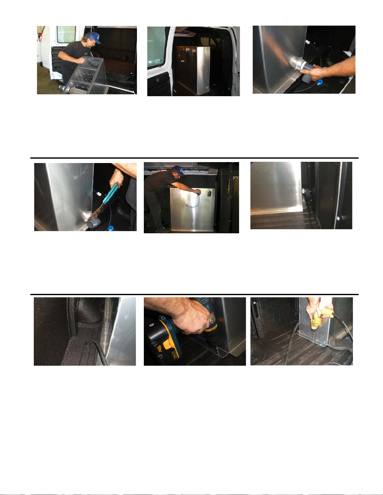
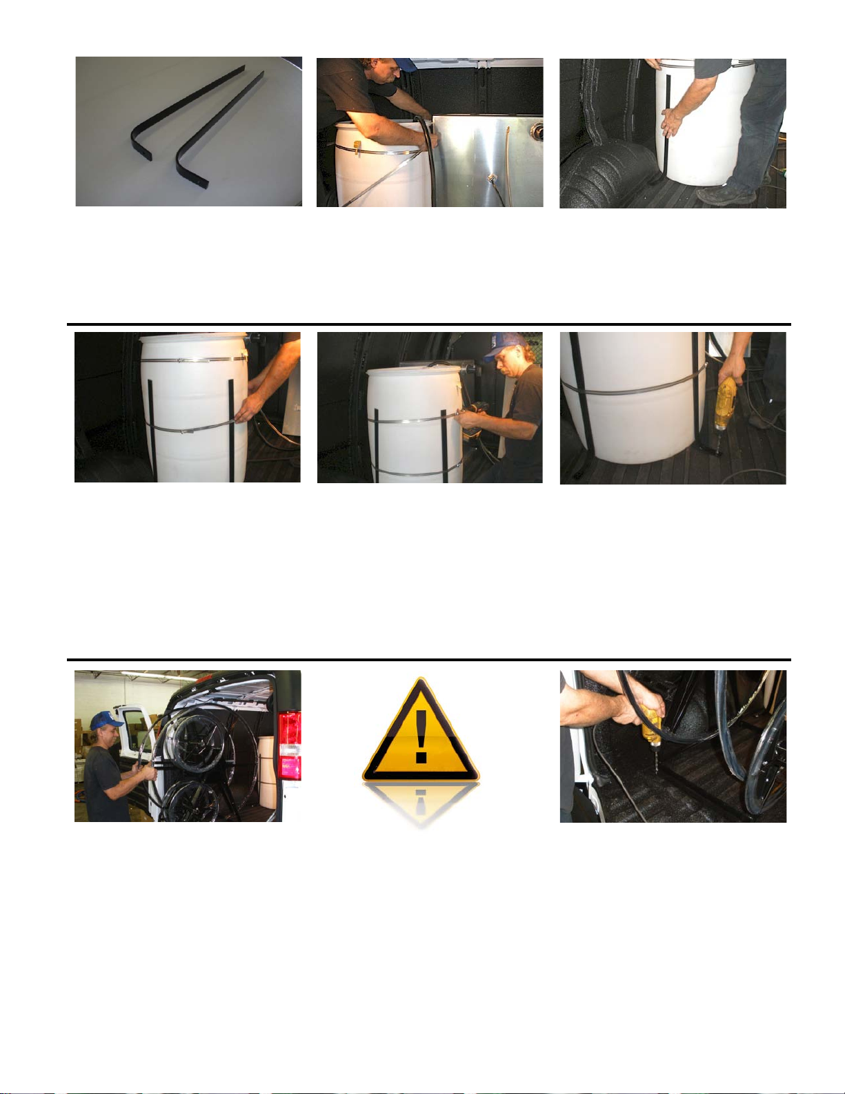
Locate the two tank support legs
and set them on the floor of the
van near the fresh water tank.
Slip strapping clamps around
the top portion of the fresh water
tank. Leave them loose.
Stand tank support legs into the
approximate position against
fresh water tank.
Slide straps down over the
support legs.
Strap support legs to tank using
two strap clamps. Tighten
securely
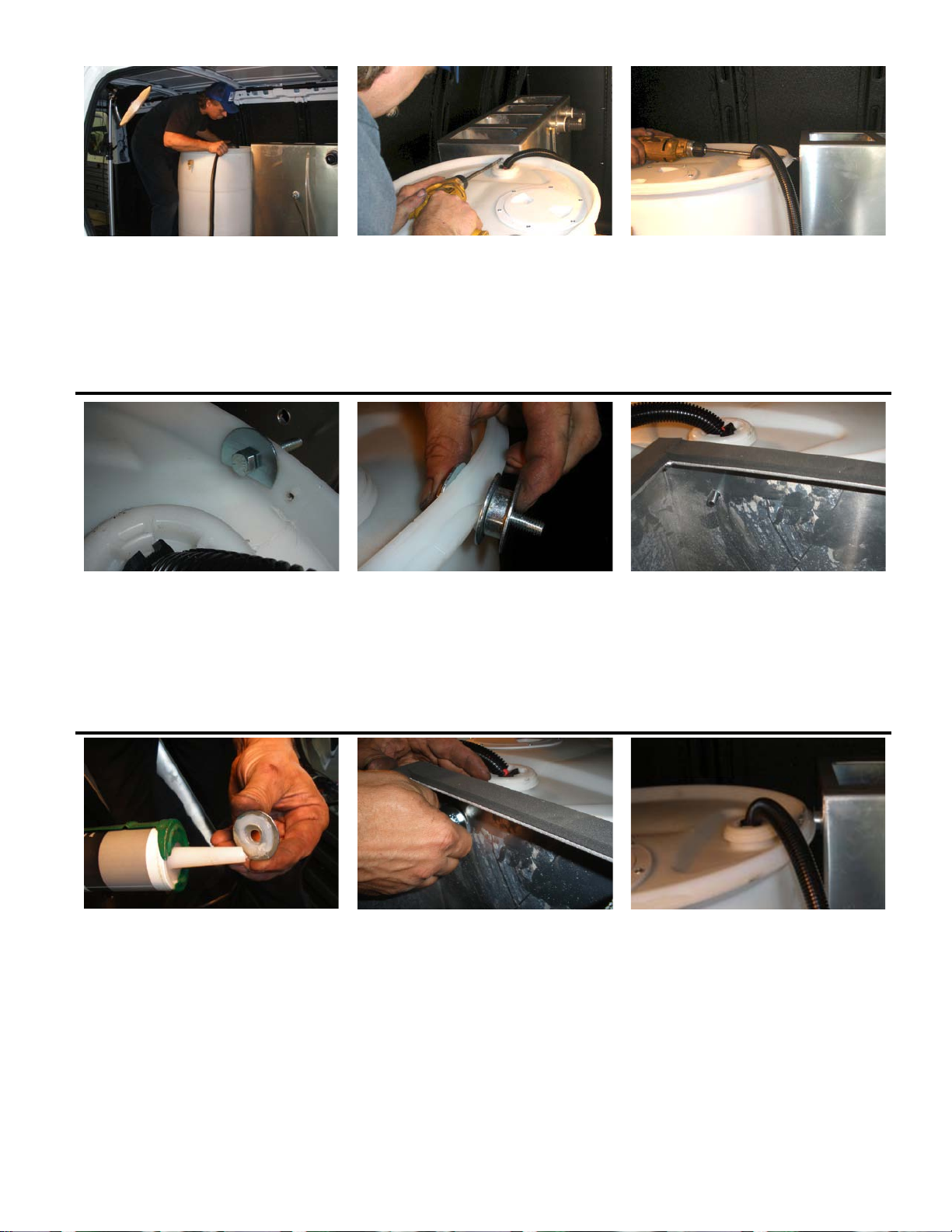
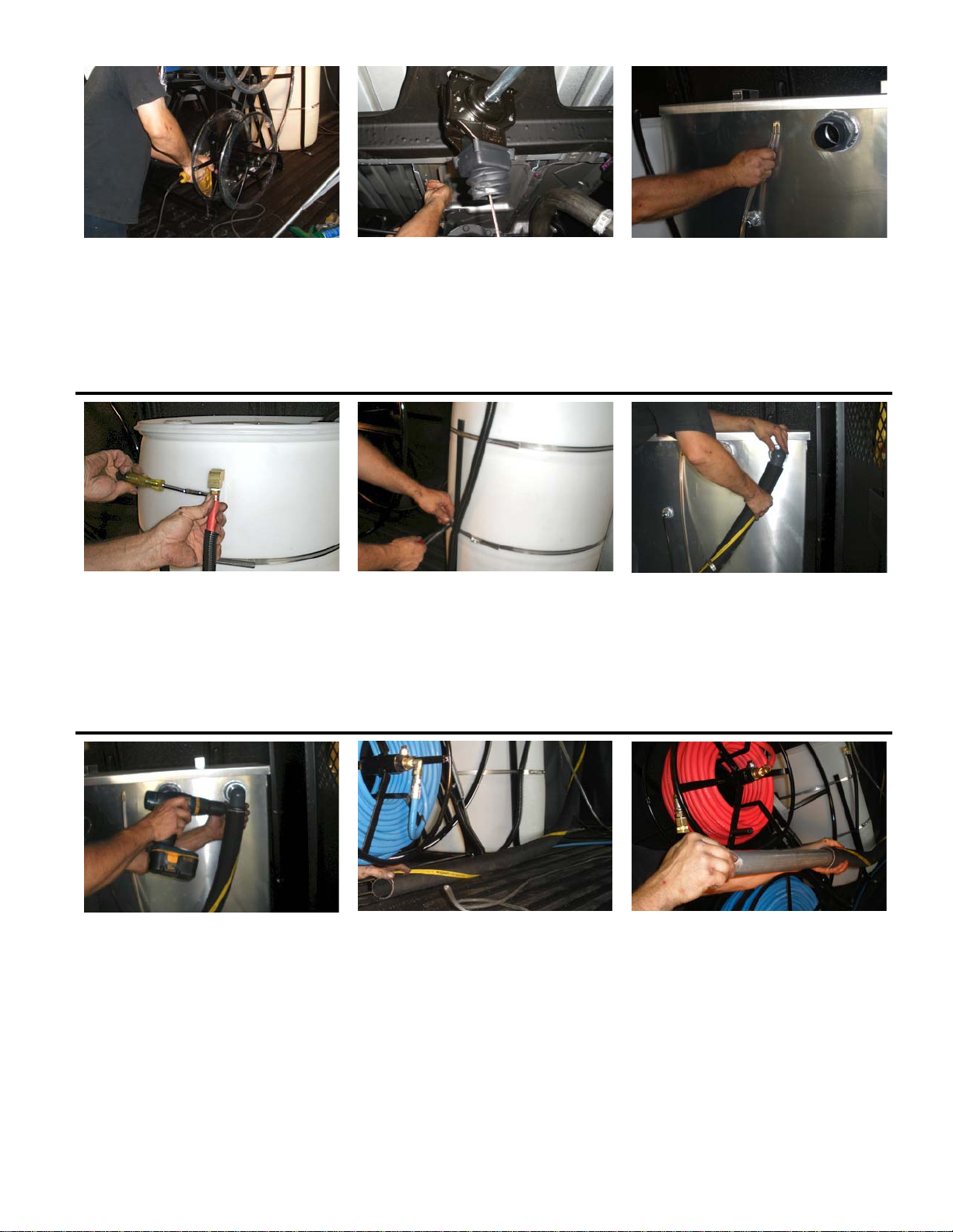
Drill 3/8” holes in floor of van
to bolt tank support legs down.
Check below van before drilling.
Drop a 5/16”x2” bolt with a flat
washer through each hole. From
below, install a fender washer and
a locknut on each bolt.
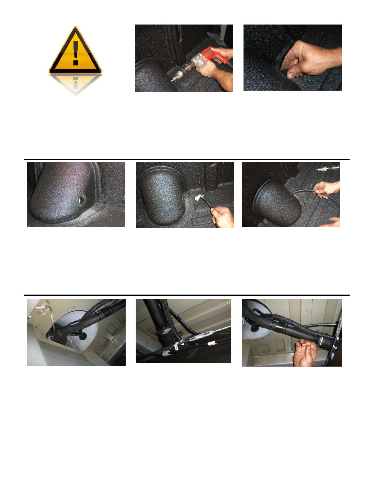
Determine which side the reels
will go on, and set into place.
Generally, it is best to set the
reels as close as possible to the
wheel well, and as close to the
doors as possible. Check to make
sure the doors will close before
drilling mounting holes.
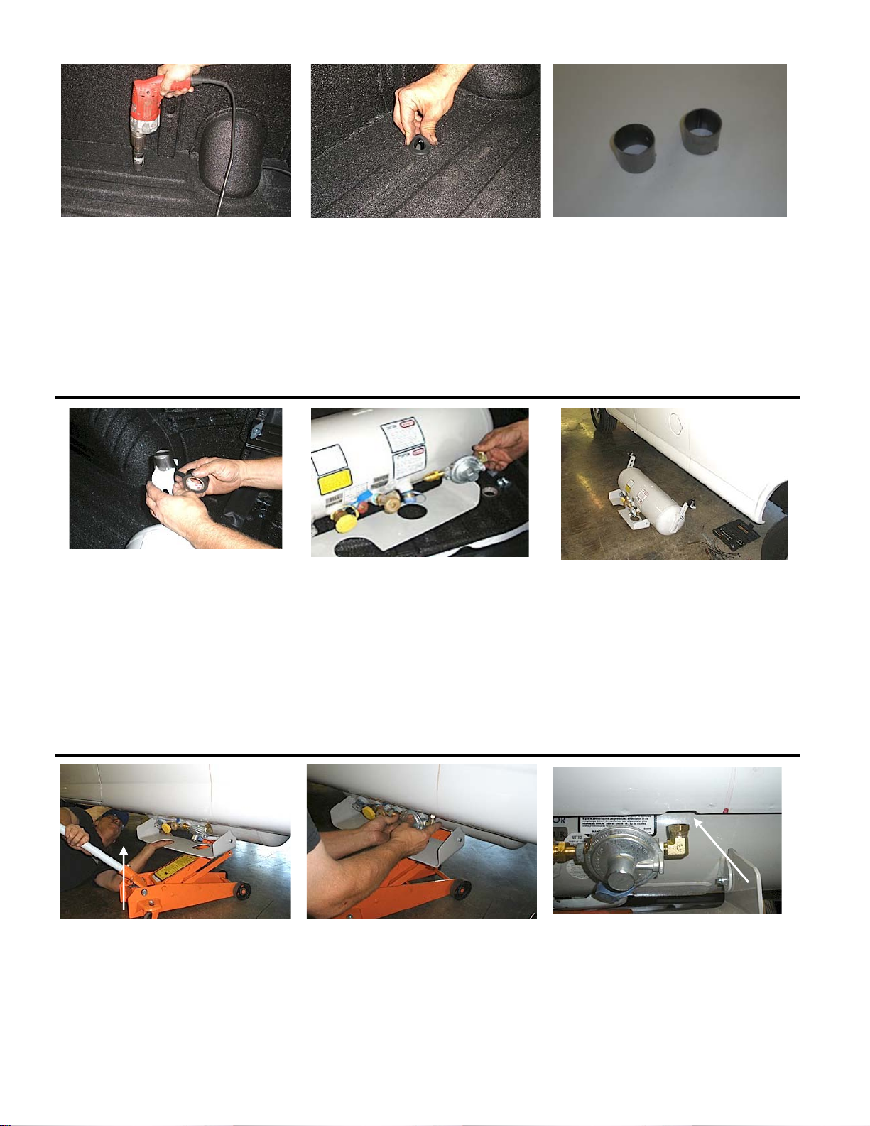
WARNING: Check below van to
make sure that you will not do
any damage when drilling the
holes for mounting the reels.
It is recommended that you take
down the spare tire to prevent
damage and make this
procedure easier.
Drill four 3/8” holes through base
of reels and floor of van.
8
Drop a 5/16”x2” bolt with a flat
washer through each hole as you
drill them. This will prevent the
reels from moving out of
alignment with the holes you
have drilled.
Install a fender washer and a
locknut onto each bolt. (Viewed
from below van with spare tire
removed)
Connect clear tubing for thermal
unloader valve. No clamp is
needed for this connection.
Connect fresh water supply line
coming from hose reels. Use a
hose clamp and secure.
Use a wire tie to secure the hose
to the tank support leg.
Connect one end of 2” waste hose
to vacuum adapter in front of
waste tank. Do not cut the hose
yet.
Tighten securely with 2” hose
clamp.
Lay hose out and cut to length. It
should reach about midway along
the base of the hose reels. Note,
this hose has a steel wire
reinforcement. You can use a
razor knife to cut the hose, but
you will need wire cutters to cut
through the steel reinforcement.
Insert aluminum vacuum tube
into hose. Make sure that at least
4” of the tube is inserted into the
hose.
9
Bring end of vacuum tube past
the base of the hose reels by
about
3-4”.
Wrap one 3” hose clamp around
the vacuum tube and reel base.
Wrap another around the end of
the hose and reel base.
Adjust the vacuum tube to where
you want it, and tighten both hose
clamps, securing the vacuum tube
and hose to the hose reel base.
Slide shelves into position.
*Shelves are optional
If necessary, you can bend the flanges on the base of the shelves so
they fit more closely to the wheel well. You can use an adjustable
wrench to do this as shown.
Once you have the shelves in
place, use a hammer to bend the
flanges to conform to the floor
surface.
Make sure the shelves sit firmly
on the floor before fastening. This
will help to keep shelves from
becoming loose and rattling.
Fasten shelves to floor using 1”
self-drilling screws. Use at least 2
screws per leg.
10
Attach top edge of shelf to pillar
with three 1” self-drilling screws.
Drill a hole through shelf at
location shown. Do not drill
through van pillar.
Attach shelf at this location with
a self-drilling sheet metal screw.
Use two more screws at the
location shown above.
Using a lift table, forklift or other
mechanical assistance, raise the
truckmount console into position
and carefully slide into van. Be
careful not to hit the top of door
opening. Do this slowly and
carefully to avoid damage or
injury.
Maneuver console into position.
In order to allow access for
maintenance, make sure that it is
a minimum of 8” from metal
cargo divider. See photo.
A metal cargo divider is strongly recommended to protect
vehicle occupants from hot surfaces, flying tools and loose
equipment in the event of a collision.
DANGER: If there is no cargo divider, adjust the passenger
seat as far back as it will go. Make sure that the console
is set so that the minimum distance is at least 12” from the
back of passenger seat.
DISABLE RECLINING ADJUSTMENT ON SEAT to prevent
seat from coming into contact with hot surfaces.
Failure to do so could result in fire, injury or death.
11
8” min.
Adjust console so that there is approximately 3-1/2” overhang in door
well. Close doors carefully to check clearance. Check both sides and
adjust until unit is square with van. (See photos)
Check under van and identify any
critical components or frame
members that could be damaged
before drilling holes to mount
console. Drill four 3/8” holes
through base of console and floor
of van. Drop a bolt into each hole
as you drill to prevent shifting.
In order to assure a good
electrical ground between console
and vehicle, use a split lock
washer between frame and flat
washer. The lock washer will cut
into paint and provide a good
connection. Do this on all 4 bolts.
Place split lock washers between
fender washer and floor of
van. Lock washers will cut into
metal van body to achieve a solid
ground connection. Failure to do
so could result in starting
problems and other electrical
issues.
You may have to bend a heat
shield out of the way to access
bolts. Check carefully before you
drill.
Sometimes it is necessary to drill
through part of the van frame. If
so, you will have to use 4” bolts
at those locations.
Connect wires from waste tank shutoff switch to wires in back of
console with spade terminals.
12
3-1/2”
3-1/2”
Split lock washer
Flat washer
Hold fuel hose up to the hose
barb on fuel pump to determine
necessary length.
Cut fuel hose to length. Connect fuel line and tighten
hose clamp.
Secure battery box to van floor
near the console with a few self-
tapping screws.
NOTE: Battery NOT included.
Recommend Group 24 Marine-
Grade with at 550 CCA (Cold
Cranking Amps).
Connect the RED (positive) wire
to the RED post (using one
washer and one locknut).
NOTE: ALWAYS connect the
positive (RED) side first to
avoid damage to electrical
components.
Connect the BLACK (negative)
wire to the BLACK post. After
both connections are secure,
place box cover over battery and
wires; secure with the included
strap.
Measure the distance between the
2 vacuum adapters and cut a
piece of 2-1/2” black waste hose
to this length.
Using a large pair of slip-joint
pliers, turn the vacuum adapter
to the side as shown. Slide two
2-1/2” hose clamps over the
waste hose and insert one end
onto the waste tank vacuum
adapter.
Holding the waste hose in
position, turn the vacuum adapter
so that it slides into waste hose.
13
Make sure that hose is snug on
both ends, and slide hose clamps
into position.
Tighten both clamps. Install supply hose from fresh
water tank to hose barb on
suction manifold.
Tighten the hose clamp. Run the clear plastic hose that is
attached to the front of the waste
tank as shown and to the back of
the console faceplate.
Cut to length and slide onto hose
barb from thermal unloader valve
(located on the pressure regulator
behind the faceplate). No hose
clamp is needed for this
connection.
Lift heater into van.
Slide heater into position. Leave
enough room between heater and
waste tank for future servicing (at
least 3”).
Use 4 self-drilling sheet metal
screws to fasten the heater down
to the floor of the van.
14
Self drilling screws
Attach propane hose to the heater.
Tighten fitting using two
wrenches.
Tie the propane hose off to the
support leg of the heater.
Remove the hose that is attached
to the top of the discharge
manifold. (This was connected
for testing purposes only)
Attach the hose you just removed
from the discharge manifold to
the water heater as shown.
Tighten with two wrenches.
Attach 3’ pressure line (included) from the cold water side of the
heater to the discharge manifold. Use two wrenches to tighten the
fittings.
Route hoses away from moving
parts and fasten to frame with
wire ties.
Install head pack holder using
self drilling sheet metal screws.
Set head pack into place. Cut
opening in head pack lid for hose
and insert chemical feed hose.
Make sure check valve strainer is
in place and that the hose reaches
the bottom of the head pack
without curling back up.
15
This completes the installation of the truckmount system. A full run-check is necessary before the unit is
put into service.
Check all fluid levels including engine oil, pump oil, and blower oil. Failure to perform this check
could result in expensive damage to major components!
DO NOT light heater until steps 1-14 have been completed! If the truckmount is equipped with an
electronically- controlled heater, turn heater switch to off position.
The following steps are recommended in this order:
1. Fill fresh water tank with at least 20 gallons of water.
2. Fill chemical solution container (head pack) at least half way with water or properly mixed extraction
detergent or rinse solutions.
3. Make sure that the pump clutch switch is turned off.
4. Attach prime/fill hose to the end of the solution hose on reel. Open the solution hose valve. Place the
end of the hose into a bucket
5. Turn chemical feed valve (on chemical feed gauge) counter-clockwise a few turns to open valve.
6. Close the choke and start engine. A few seconds after starting, slowly open the choke.
7. Allow engine to run at idle for about 30 seconds, and slowly open the throttle to full speed.
8. Once engine is running smoothly at full speed, turn on the pump switch. After a few moments, water
should begin to flow into the bucket.
9. Check to make sure that solution is flowing through chemical feed gauge. There should be no bubbles
after the first few moments. Set gauge to 2 GPH.
10. Run about 2-3 gallons of water into bucket.
11. Slowly close the ball valve on solution hose and adjust pressure to 400-500 psi.
12. Turn off solution pump switch. Leave engine running.
13. Attach a cleaning tool to the solution hose as you would for cleaning.
14. Open propane valve on propane tank.
15. Light the pilot according to the instructions printed on the heater. This may take a couple of minutes
as the propane hose is filled with air. Once air is purged and propane enters heater will light.
16. Once pilot is lit, set temperature control to “HOT” and turn heater control valve to the “ON”
position. Heater should light.
17. Turn on pump switch. Repeatedly trigger cleaning tool in a 10 seconds “on”, 5 seconds “off”
sequence. You should get hot water within 1-3 minutes.
18. While unit is running and pump is on, take a few moments and check all hose connections and
fittings behind console faceplate and on heater. Check for leaks, and tighten any fittings that
drip.
19. Block off vacuum port and check that the vacuum relief (pop-off) valve is adjusted properly. (See
Owners’ manual for correct vacuum relief adjustment.) Make sure that the waste tank dump valve is
completely closed. Listen for vacuum leaks around waste tank lid and at vacuum hose connections.
20. Unblock vacuum port, and turn off solution pump. Key the wand to release pressure from system.
21. Turn off heater.
22. Move engine throttle to idle (On Kohler engines set throttle at half speed) and run 5-10 seconds.
23. Turn engine off. Close propane valve on propane tank.
Initial startup test is now complete.
16

This manual suits for next models

2

Other TCS Industrial Equipment manuals

TCS CS-105 User manual

TCS

TCS CS-105 User manual

TCS TC-HS V2 Operation instructions

TCS

TCS TC-HS V2 Operation instructions

Popular Industrial Equipment manuals by other brands

ABB HT563856 Operation manual

ABB

ABB HT563856 Operation manual

Metso Outotec Lokotrack ST4.8 DRIVING INSTRUCTION

Metso Outotec

Metso Outotec Lokotrack ST4.8 DRIVING INSTRUCTION

Kingspan Klargester BioAir DS1398P Installation & operation

Kingspan

Kingspan Klargester BioAir DS1398P Installation & operation

schmersal AZM400Z-ST-1P2P-T Instructions for operation and use

schmersal

schmersal AZM400Z-ST-1P2P-T Instructions for operation and use

IEMCA Smart 320 Tp Manual for use and maintenance

IEMCA

IEMCA Smart 320 Tp Manual for use and maintenance

BOSSLASER LS Series quick start guide

BOSSLASER

BOSSLASER LS Series quick start guide

GPL 750 Installation and maintenance manual

GPL

GPL 750 Installation and maintenance manual

Danfoss BOCK F operating guide

Danfoss

Danfoss BOCK F operating guide

Kval Edge-SS Operation manual

Kval

Kval Edge-SS Operation manual

AGC SMART 51/33 Image processing guide

AGC

AGC SMART 51/33 Image processing guide

ABB HT608016 Operation manual

ABB

ABB HT608016 Operation manual

SWF RTS Programming instructions

SWF

SWF RTS Programming instructions

PI MS235E user manual

PI

PI MS235E user manual

Enerpac SHS Operation and maintenance manual

Enerpac

Enerpac SHS Operation and maintenance manual

Siemens 3VA9 7-0NA10 Series quick start guide

Siemens

Siemens 3VA9 7-0NA10 Series quick start guide

DX Engineering DXE-RT-4500HD manual

DX Engineering

DX Engineering DXE-RT-4500HD manual

Baileigh Industrial BP-3305CNC Operator's manual

Baileigh Industrial

Baileigh Industrial BP-3305CNC Operator's manual

ABB SACE Tmax XT Series manual

ABB

ABB SACE Tmax XT Series manual

manuals.online logo
manuals.online logoBrands
  • About & Mission
  • Contact us
  • Privacy Policy
  • Terms and Conditions

Copyright 2025 Manuals.Online. All Rights Reserved.