TCS AMI11603 User manual

Product information
Display module LCD graphic, 3 buttons
AMI11603
for 256 flats
Note on the validity of this product information
This product information contains specific information on the modules. It is only valid in combination with
the enclosed product information Module of the seriesAMI in front-door stations.

2
Table of contents
Scope of delivery..........................................................................................................................................................3
Introduction..................................................................................................................................................................3
Notes on this product information....................................................................................................................................................................3
Used symbols and warning notices ................................................................................................................................................................3
Further used symbols .......................................................................................................................................................................................3
Safety instructions.......................................................................................................................................................4
General safety regulations ...............................................................................................................................................................................4
Requirements to protect against lightning ......................................................................................................................................................4
Product description .....................................................................................................................................................4
Intended use ......................................................................................................................................................................................................4
Short description................................................................................................................................................................................................4
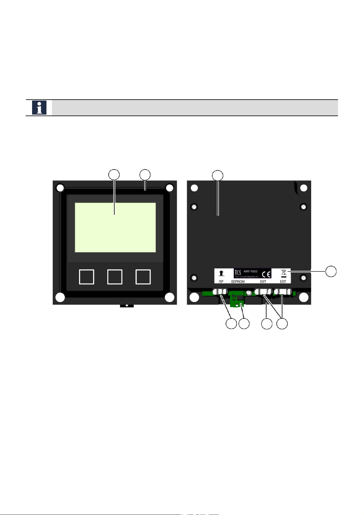
Device overview ................................................................................................................................................................................................5
Indication and operating elements ..................................................................................................................................................................5
Technical data ...................................................................................................................................................................................................6
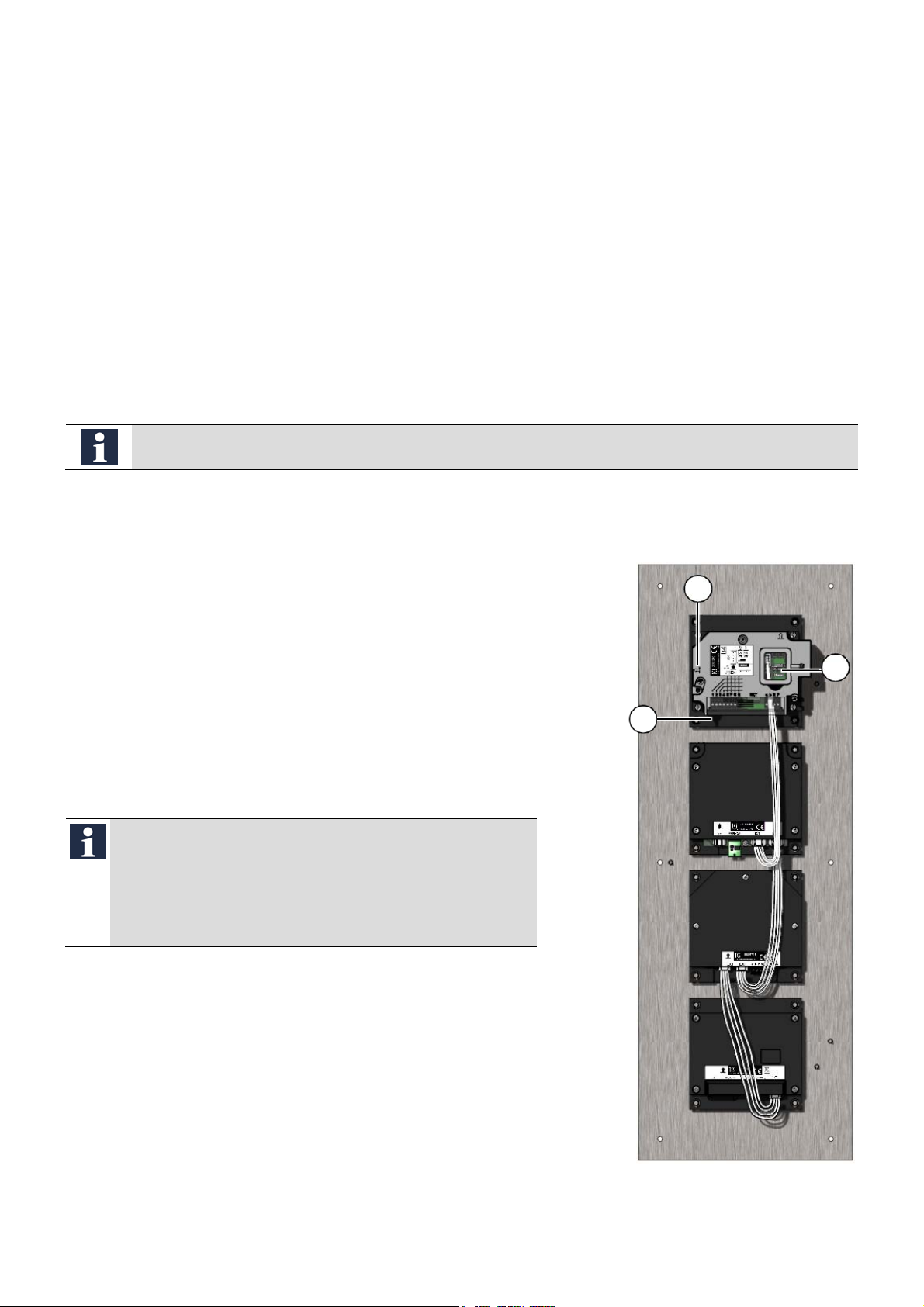
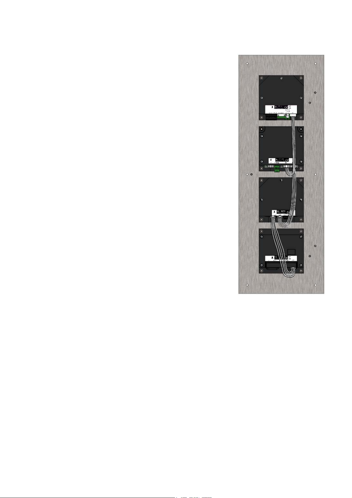
Mounting and installation ............................................................................................................................................7
Connecting the lines..........................................................................................................................................................................................7
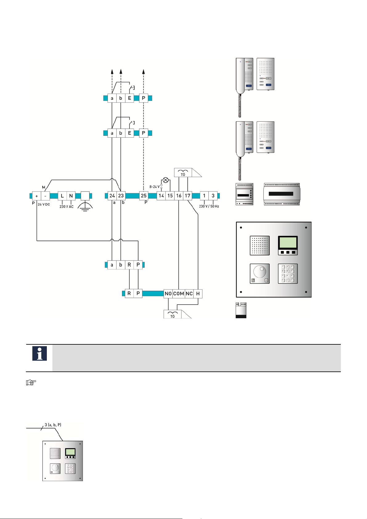
Example circuit ..................................................................................................................................................................................................9
Wiring diagram ..................................................................................................................................................................................................9
Initial operation..........................................................................................................................................................10
Operating modes............................................................................................................................................................................................ 10
Configuration .............................................................................................................................................................11
Factory settings .............................................................................................................................................................................................. 11
Configuration options..................................................................................................................................................................................... 12
Operation....................................................................................................................................................................13
Calling / speaking to residents via ................................................................................................................................................................ 13
… smart keys (display module) .................................................................................................................................................................... 13
… jogwheel module AMI10410.................................................................................................................................................................... 14
… codelock module AMI11200.................................................................................................................................................................... 15
Door release via code entry .......................................................................................................................................................................... 16
Repair.........................................................................................................................................................................17
Replacing the EEPROM ............................................................................................................................................................................... 17
Trouble shooting........................................................................................................................................................18
Cleaning .....................................................................................................................................................................19
Conformity .................................................................................................................................................................19
Information on disposal.............................................................................................................................................19
Warranty ....................................................................................................................................................................19
Spare parts, accessory ..............................................................................................................................................20
Service........................................................................................................................................................................20

3
Scope of delivery
1x display module LCD graphic AMI11603-00xx
3x distance foil 0.5 mm
1x connection cable with 4 pins
4x securing nut M4
1x product information display module LCD graphic, 3 buttons AMI11603
1x product information modules of the series AMI in front-door stations
Introduction
Notes on this product information
This product information refers exclusively to qualified electricians.
The product information contains important notes on intended use, installation and initial operation. Please, keep the
product information at a suitable place, where it is easily accessible for maintenance and repair reasons.
All product information are available in the download area at www.tcsag.de .
Used symbols and warning notices
Symbol signal word Explanation
DANGER! The signal word describes an endangering with a high level of risk. Failure to observe this warn-
ing will result in death or very serious injury.
WARNING! The signal word describes an endangering with a medium level of risk. Failure to observe this
warning could result in death or very serious injury.
CAUTION! The signal word describes an endangering with a low level of risk. Failure to observe this warn-
ing could result in a minor or moderate injury.
ATTENTION! The signal word indicates, that damages on equipment, environment and property can occur.
Further used symbols
important note or important information
►Step
cross reference For further information on this topic, see source
list, list entry 1 level
‐
list, list entry 2 level
a) Explanation

4
Safety instructions
General safety regulations
Assembly, installation, commissioning and repair of electronic devices must be carried out by qualified
electricians.
Observe the latest regulations and standards for system installations.
WARNING! Danger to life due to electric shock
Observe the safety regulations according to DIN VDE 0100, when working on main power connections of
230 V.
When installing TCS:BUS systems the general safety regulations for telecommunication systems ac-
cording to VDE 0800 must be observed. Inter alia:
separated cable routing of high and low voltage lines,
minimum distance of 10 cm in case of a common cable routing,
use of separators between high and low voltage lines within shared cable ducts,
use of standard telecommunication lines, e.g. J-Y (St) Y with 0.8 mm diameter,
already existing lines (modernisation) with deviating cross-sections can be used in compliance with
the loop resistance.
Requirements to protect against lightning
ATTENTION! Device damage due to over-voltage
By suitable lightning protection measures it has to be ensured that the electric voltage of 32 V DC at each
connection is not to be exceeded.
Product description
Intended use
The display module LCD graphic AMI11603is a module of the front-door station series AMI. The display module
LCD graphic AMI11603 is suitable for the operation in TCS video systems and combined audio / video systems.
The display module can be used only in combination with a built-in door loudspeaker module AMI11x0, a codelock
module AMI11200 or another module with a 4-pin connection cable. The display module cannot be combined with
the jogwheel module AMI10400 and the keypad module AMI10300. In combination with the jogwheel module
AMI10410 (with reduced speed) a quick and easy selection within in the list is feasible. In combination with the
codelock module AMI11200 (operating mode: keyboard) a direct input of flat numbers at the codelock module is
possible.
For applications, which differ from the intended use or goes beyond it, the manufacturer accepts no lia-
bility.
Short description
for up to 256 flats
fully graphical, monochrome display with 160 x 104 pixel, white backlight
residents can be called via an alphabetical sorted name list (optionally via input of the flat number or access code
via codelock module)
language can be changed, also non-Latin characters can be displayed

5
3 illuminated buttons (smart keys) for an easy operation
connection via a 4-pin service socket of the built-in door loudspeaker module AMI11100
further connection for outgoing connection to another module
acknowledgement tone output via central module (e.g. built-in door loudspeaker module)
optical error indication
resident data base: 256 data sets (names with 24 digits, flat number with
6 digits, 2 serial numbers per resident, max. 10-digit call number for telephone direct dial) a)
The EEPROM data base is not compatible with AD1 resp. AD2.
configuration onl with the configuration software configo™
update via ISP interface feasible
a) Options in case of activatedfunction: FBO1100 direct dial
Device overview
Fig. 1: Front view Fig. 2: Rear view
1 display with backlight 5 2 connections with 4 pins (EXP)
2 front panel sealing 6 drainage channel for condensed water
3 housing 7 EEPROM
4 type label 8 connections with 3 pins (ISP)
Indication and operating elements
The display module LCD graphic AMI11603 is equipped with 3 smart keys as operating elements. The function of
this smart keys differs, depending on the displayed screen.
1
2
3
4
8
7
6
5

6
Legend button assignment
no reaction - button is not assigned
call up input flat number / telephone number
call up name list (resp. initial character, if configured in this way)
jump to the next character
start entry code number
call up name list (resp. initial character, if configured in this way)
back / repeat entry
delete character to the left of the cursor
back to the idle screen, end voice connection
call the selected call destination (name or flat number)
end and confirm entry
select previous name (line) from the name list
select succeeding name (line) from the name list
call up additional information after a door call (speech channel is busy; serial number 1 and 2 acknowledged)
Legend actions
indoor station(s) is (are) called breakdown (see page 18)
indoor station could not be called (ring tone is switched
off, indoor station 1 and/or 2) error a)
voice connection; speech channel is not busy
temperature sensor was not found (check serial number,
temeperature sensor)
voice connection terminated; speech channel is busy
acknowledgement of indoor station with serial number 1
OK
code number entry
acknowledgement of indoor station with serial number 2
OK
code number known, door opener is triggered
acknowledgement serial number 1 not OK (analogue SN
2)
code number unknown, door opener is not triggered
a) in combination with the following symbols:
The serial number is unknown or no dataset is available.
An unknown indoor station has start avoice connection.
No code number entry before pressing the button or the code number is unknown.
An unknown indoor station is called.
Technical data
supply voltage +24 V ± 8 % (power supply and control unit)
input current in resting position I(a) = 0.11 mA, I(P) = 7.8 mA
max. input current: I(Pmax) = 86 mA
acceptable ambient temperature -25 ... +55 °C
housing aluminium, anodised
display plastics
buttons plastics with insert made of aluminium anodised
dimensions (in mm) H 105 x W 105 x D 22
weight 270 g
3-wire technique necessary!

7
Mounting and installation
Requirements to the installation location
Harmful environmental conditions can lead to a shortened life cycle or to malfunctions.
Install and operate the display module AMI11603 not at locations with direct solar radiation or inappropriate tem-
peratures (see. Fehler! Verweisquelle konnte nicht gefunden werden., page Fehler! Textmarke nicht
definiert.).
Connecting the lines
Internally connect the module in the front-door station
The display module AMI11603 can be connected to a built-in door loudspeaker module AMI111x0 or to modules
with a 4-pin connection cable.
First install the AMI modules into the front panel, than wire them together.
Connection to built-in door loudspeaker module AMI11100, codelock module AMI11200 and jogwheel
module AMI10410
At the built-in door loudspeaker module AMI11100:
►Remove the terminal cover (3).
►Open the cap of the service opening (2).
►Plug the 4-pin connection cable on the service plug in the service
opening.
►Guide the cable below the cap of the module (1) out to the termi-
nals.
►Close the service opening and the terminal cover.
►Connect the cable of the built-in door loudspeaker to the display
module.
►Connect the codelock module AMI11200 and the jogwheel mod-
ule AMI10410.
Commissioning
The AS addresses of the bell button modules and the built-in
door loudspeaker module resp. display module have to be
identically to establish a connection.
►Adjust the AS addresses to the same value and block
them.
Fig. 3: ZAU2004-0030 incl. AMI modules
3
2
1
AMI11100
AMI11603
AMI11200
AMI10410

8
Connection to TCS:BUS speech module AMI11110, codelock module AMI11200 and jogwheel module
AMI10410
At the TCS:BUS speech module AMI11110:
►Connect the cable of the built-in door loudspeaker to the display
module.
►Connect the codelock module AMI11200 and the jogwheel mod-
ule AMI10410.
Fig. 4: ZAU2004-0030 incl. AMI modules
AMI11110
AMI11603
AMI11200
AMI10410

9
Example circuit
Fig. 5: Circuit diagram
Note on FBS2100:
Optionally a temperature sensor (not enclosed in the delivery) can be used to indicate the temperature in
the display.
For further information see TCS system manual. The TCS system manual can be downloaded at
www.tcsag.de.
Wiring diagram
ISH3030
ISW3030
ISH3030
ISW3030
BVS20
NGV1011
front-door station (connect to AMI111x0)
FAA1100
floor push
button
floor push
button
lights
door opener
door opener
front-door station:
-display module with 3 buttons
(AMI11603)
-built-in door loudspeaker (AMI111x0)
-jogwheel module (AMI10410)
-
codelock module (AMI11200)

10
Initial operation
Operating modes
selection
resident lis
t
entr
y
flat numbe
r
code entr
y
selection
initial characte
r
direct entry of the
call number for FBO1100 a)
transfer of the call number
with control function for
FBO1100 b)
Standard (stand alone
or with jogwheel module) X - - X - X
Basic (with codelock module) - X X - X X
Extended (with codelock module and jogwheel
module) X X X X - X
a) Only possible, when the AD2 mode is activated and thecodelock module is connected. The call number with 10 digitscan be entered directly
via the codelock module.
b) Only possible, when the AD2 mode is activated. Transferringthe call number is implemented byselecting the name or the flat number.
►Install all AMI modules completely and establish all internal connections.
►Install the devices of the system completely.
►Proof the a-, b- and P-wire against each other on short-circuit.
►Switch on the mains voltage.
Device start-up
After switching on the device, the start screen appears for 5 sec. with
the following indications:
software version of the device
hardware version of the device
device mode
The device mode is detected automatically (standard, basic
or extended).
Type of device
Fig. 6: device start-up standard
operating
mode
possible functions

11
Standby mode
10 sec. after switching on the device, the start screen appears. The
device is in standby mode.
In delivery state the TCS logo is displayed.
Standard (optionally with jogwheel module AMI10410)
Basic (only with codelock module)
Extended (with codelock module and jogwheel module)
Fig. 7: standby mode Standard
Fig. 8: standby mode Basic
Fig. 9: standby mode Extended
Configuration
The display module can be configured exclusively with the configuration software configo™.
The module cannot be configured manually via the buttons as well as via the Service Device TCSK.
The configuration software configo™ can be used also by the end user, e.g. the property management to update
the name list.
For the configuration you need the maintenance package FBI1210-0 (or FBI1200-0).
All configuration data and the resident data base are stored on the EEPROM.
Additionally these data are transferred automatically to the EEPROM after each configuration. The EEPROM can
be removed if necessary, without functional impairment.
Factory settings
The device is equipped with an EEPROM. Within the EEPROM, the following device settings are stored ex works:
mode backlight automatic operation
1)
start screen TCS logo
data base no data sets
temperature sensor a
)
deactivated
unit of temperature °C (Celsius)
indication in AD2 mode activated
FBO1100 direct dial deactivated
activate pre-selection via initial character deactivated
a) temperature sensor:
A temperature sensor, flush-mount, single, FBS2100-0600 can be used.
Preset times
timeout for backlight in automatic mode 30 sec
error detection "button stucks" (press the button longer than 25 sec) 25 sec

12
Configuration options
function configoTM
as of version 1.8.x.x
create resident list (allocation of the 1st and 2nd indoor station to name and number) x
Determine the AS address x
activate the temperature indication x
switch over the temperature specification to unit °F (Fahrenheit) x
activate the AD2 mode b
)
x
activate FBO1100 direct dial b
)
x
activate chapter resident list pre-selection b
)
x
select mode backlight (always OFF, always ON, automatic mode a
)
, depending on the brightness) x
select start screen (TCS logo, temperature, none) x
a) automatic mode:
The backlight is switched off in standby mode. The user can activate it at the front-door station ans it is switched off automatically after 30sec.
The backlight is activated by one of the following actions:
pressing a smart key at thedisplay module
pressing a button at the codelock module (operation mode keyboard)
operating the jogwheel module
pressing a button at the bell button module
b) Explanations:
AD2 mode is activated: the name of theresident is displayed. Not activated: only theflat number is displayed.
FBO1100 direct dial is activated: a telephone can be called directly(call number with max. 10 digits incombination with AMI11603) activate
pre-selection via initial character: when pressing a smart key, a list of available initialcharacters is displayed from which you can getto thetotal
list of the selected character (recommended only for extensive resident data bases).

13
Operation
Calling / speaking to residents via
… smart keys (display module)
Standby mode
standard
Fig. 10: standby mode Standard
Selecting a name
Select initial character:
►Press one of the smart keys . All initial characters, that are
available in the list, are displayed.
An empty resident data base is displayed with …….. .
Browse through the initial character:
►Press the smart key repeatedly until the required initial char-
acter is marked (fig. 12).
►Confirm the selection with the smart key . The resident list is
displayed. The first name with the selected initial character is
marked (fig. 13).
The list of available initial characters is only displayed, if the
chapter pre-selection resident list was activated via the con-
figuration software configo™. Otherwise the resident list is
displayed immediately.
Browse through the resident list:
►Press the smart key to browse downwards resp. the smart
key to browse upwards.
Fig. 11: select initial character
Fig. 12: browse
Fig. 13: resident list
Calling a resident
►Press the smart key . The selected resident is called and the
name is displayed (fig. 14).
If the telephone does not respond resp. the front-door station
receives no acknowledgement, the indication appears (fig.
15).
Fig. 14: call resident
Fig. 15: telephone does not respond

14
Speaking
After accepting a call, the indication established voice connection is
displayed (fig. 16).
Fig. 16: established voice connection
… jogwheel module AMI10410
Standby mode
standard
Fig. 17: standby mode Standard
Selecting a name
select initial character:
►Turn the jogwheel. The resident is displayed and the first name is
marked (fig. 18).
►Alternatively press the ABC button at the jogwheel module. All
initial characters, that are available in the list, are displayed.
Browse through the initial character:
►Turn the jogwheel until the required initial character is displayed.
►Confirm your selection with the smart key or . The resi-
dent list is displayed and the first name with the required initial
character is marked.
Browsing through the resident list:
►Turn the jogwheel until the required name is marked.
The list of available initial characters is only displayed, if the
chapter pre-selection resident list was activated via the con-
figuration software configo™. Otherwise the resident list is
displayed immediately.
Fig. 18: resident list
Fig. 19: list of available initial characters
Fig. 20: resident list
Speaking
After accepting a call, the indication established voice connection is
displayed (fig. 23).
Fig. 21: established voice connection

15
… codelock module AMI11200
The operation is implemented via codelock module within keyboard modea) and via smart keys.
Standby mode
Basic
Fig. 22: standby mode Basic
Entering the flat number
If the flat number is known, you can enter it directly.
►Enter the flat number (fig. 25) with the buttons 0 to 9 at the
codelock module.
►To correct your entry press the smart key .
Fig. 23: flat number
Calling a resident
►Press the smart key or the #-button at the codelock module.
The selected flat number b) is called and displayed (ill. 26).
If the telephone does not respond resp. the front-door station
receives no acknowledgement, the indication appears (fig.
26).
Fig. 24: Calling the flat number
Fig. 25: telephone does not respond
Speaking
After accepting a call, the indication established voice connection is
displayed (fig. 28).
Fig. 26: established voice connection
a) Select via configuration software configo™ (> access control >codelock module AMI11200: keyboard mode.
b) Enter under apartment number in configo™: Flat number, serial number of theindoor station, number of the dataset, telephone number or
number of the control function when connecting to the TK system.

16
Door release via code entry
The operation is implemented via codelock module within keyboard modea) and via smart keys.
Standby mode
Basic
Fig. 27: standby mode Basic
Start entry code number
►Press the smart key or the #-button at the codelock module.
The indication code entry is displayed (fig. 30).
Fig. 28: Code entry
Entering the code number
►Enter the code with 1 to 4 digits at the codelock module.
►Confirm your entry with the smart key or the #-button at the
codelock module.
If the code is valid, the door opener is triggered (fig. 32).
If the code is invalid, the door opener is not triggered (fig.
33). Press the smart key to enter the code again.
If the code is entered wrong 3 times, the code entry is
blocked for 3 min.
Fig. 29: 4-digit code
Fig. 30: correct code entry
Fig. 31: wrong code entry
a) Select and determine via configuration software configo™(> access control >codelock module AMI11200: keyboard mode.

17
Repair
Replacing the EEPROM
All configuration data and the resident data base are stored on the EEPROM. Additionally these data are transferred
automatically to the EEPROM after each configuration.
If the display module needs to be exchanged, the EEPROM storage can be removed from the defect module and
can be inserted into the new module.
Switch off the mains voltage at the front-door station.
►Open the front-door station.
►Disconnect the display module from the mains voltage and pull
out all connecting plugs.
►Deinstall the defect display module from the front panel.
►Remove the EEPROM (1).
►Install the new display module into the front panel.
►Plug the EEPROM on the pins of the new display modules.
Ensure the correct installation of the EEPROM into the dis-
play module. The component side (2) of the EEPROM must
be visible (fig. 34).
►Connect the display module again.
►Switch on the mains voltage. The data is transferred automatically
to the new EEPROM.
If the data transfer should be incorrect, press all 3 smart keys
simultaneously until the device restarts (after around 10
sec.).
Fig. 32: Deinstalling the EEPROM
1
2

18
Trouble shooting
Error pattern / problem Possible causes Solution
a-wire is not connected
connect the a-wire,
device is in standby mode again
a- and P-wire are interchanged or short-
circuited
change a- and P-wire or remove short-
circuit
device is in standby mode again
EEPROM error:
defect, is missing or plugged incorrectly
Ensure that the module is voltage-free!
Plug the EEPROM (correctly) on the pins.
The component side must be visible.
Connect the module again.
device is in standby mode again
Button stucks (press longer than 25 sec)
release the button,
device is in standby mode again

19
Cleaning
ATTENTION Loss of function due to short-circuit and corrosion.
Water and cleaning agents can enter the device. Electronic components can get damaged due to short-
circuit and corrosion.
Avoid water and detergents from entering the device. Clean the device with a dry or slightly wet cloth.
ATTENTION! Damages on the surface of the device.
Abrasive and scratching detergents damage the surface of the device.
Do not use any abrasive detergents!
Remove stronger stains with a pH neutral household cleaner.
Conformity
Declarations of conformity are available for download under www.tcsag.de.
Information on disposal
Dispose the device separately from domestic waste via a collection point for electronic scrap. Ask your
county administration for the responsible collection point.
Dispose the parts of the packaging in collecting tanks for cardboard and paper resp. plastics.
Warranty
We offer a simplified processing in case of warranty for qualified electricians.
Our standard terms and conditions of sale you'll find under www.tcsag.de.

20
Spare parts, accessory
Short text Article number
Spare parts
EEPROM for AMI11603 0035310
Accessory
Maintenance package FBI1210-0
temperature sensor, flush-mount, single FBS2100-0600
flush-mount kit or K3 post for 1 to 6 modules ZAU200x
Service
Please send your questions and inquiries to
Headquarters
TCS TürControlSysteme AG, Geschwister-Scholl-Str. 7, 39307 Genthin | Germany
FON: +49 (0) 3933/8799-10, FAX: +49 (0) 3933/879911, www.tcsag.de Subject to technical changes.
TCS Hotline Germany
time of printing: 11/2015
AMI11603 4A
Table of contents