TCS ISH3130 User manual

TCS TürControlSysteme AG Subject to technical changes.
E-Mail: hotline@tcsag.de www.tcsag.de PI_ISH3130-uk.doc 1A
Product information
Door telephone with comfort functions
ISH3130

2 07/2012
TCS TürControlSysteme AG Subject to technical changes.
E-Mail: hotline@tcsag.de www.tcsag.de PI_ISH3130-uk.doc 1A
Table of contents
Scope of delivery...............................................................................................................3
Safety instructions.............................................................................................................3
Installation –protective measures....................................................................................3
Intended use.......................................................................................................................3
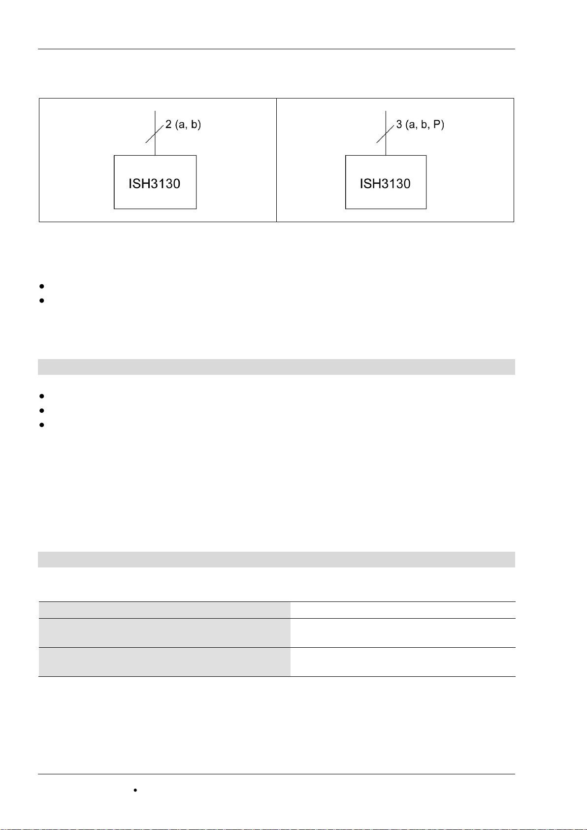
Max. number ISH3130 in 2-wire operation.......................................................................3
Max. number ISH3130 in 3-wire operation.......................................................................4
Indication and operating elements...................................................................................4
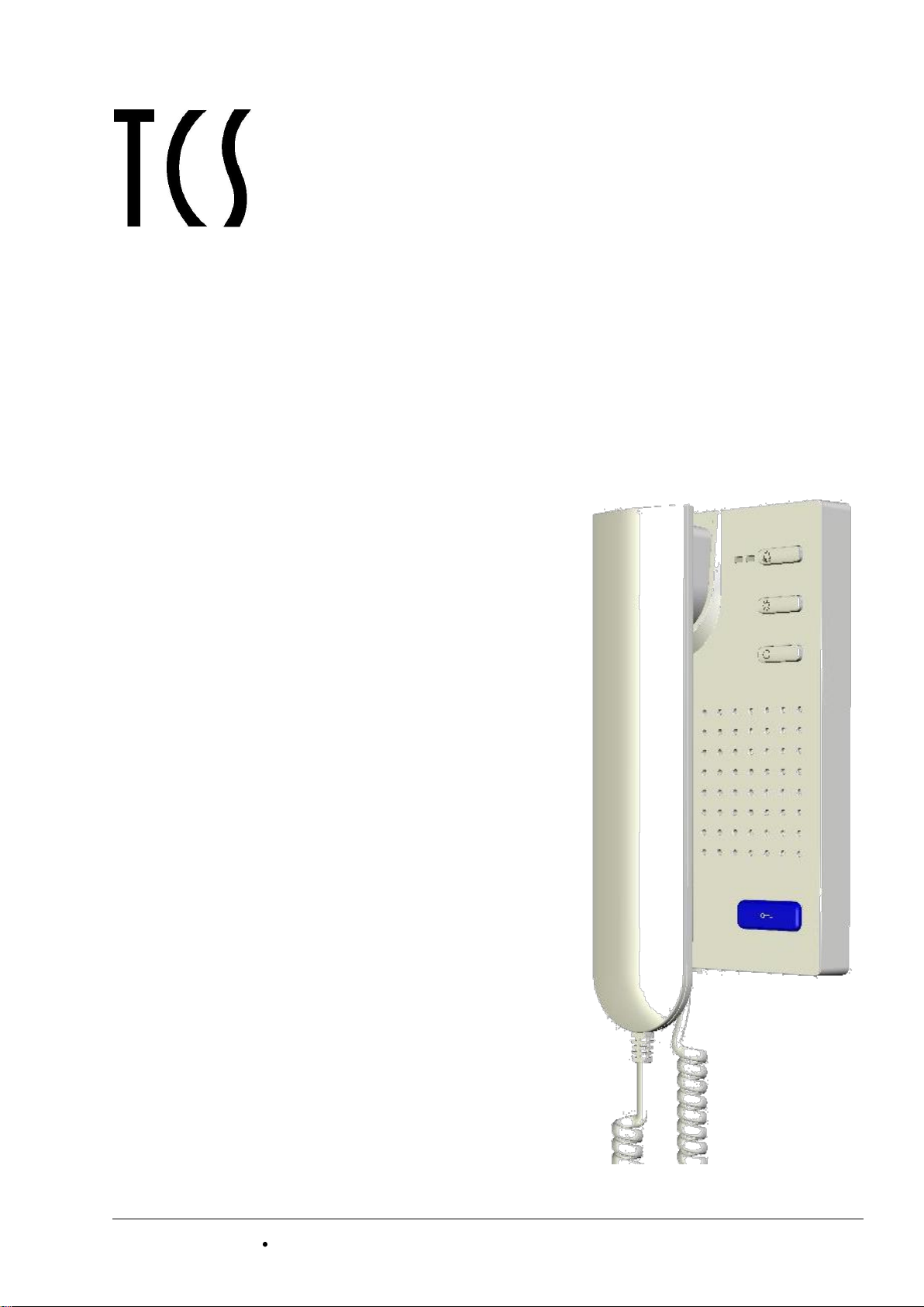
Device overview.................................................................................................................5
Technical data....................................................................................................................5
Short description...............................................................................................................6
Installation..........................................................................................................................6
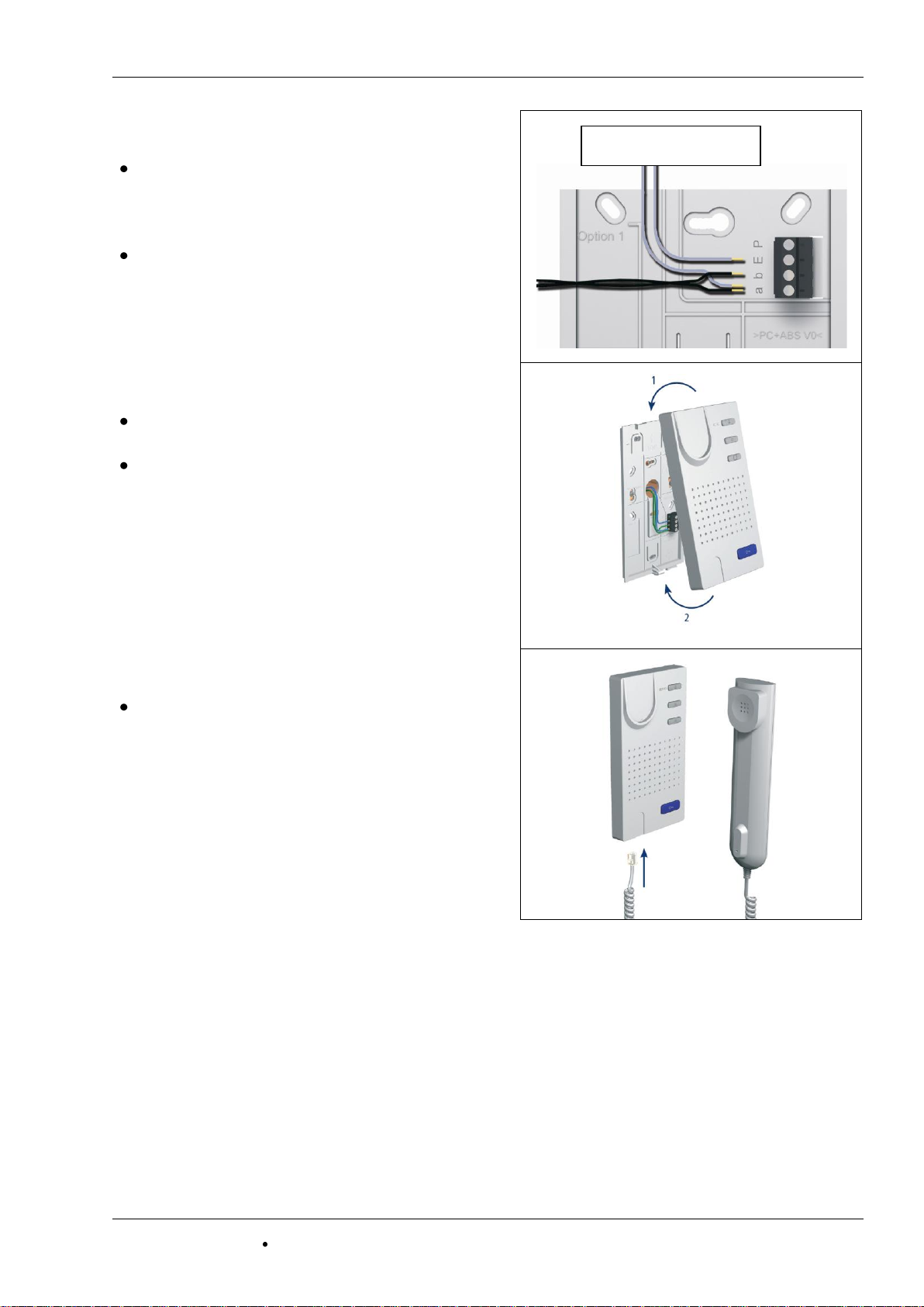
Install the lower cover.......................................................................................................6
Connect the lines (2-wire technique)................................................................................7
Snap on the upper cover..................................................................................................7
Connect the handset........................................................................................................7
Open the device...............................................................................................................8
Build-in extended functions ..............................................................................................8
Connect the lines...............................................................................................................9
Connecting lines...............................................................................................................9
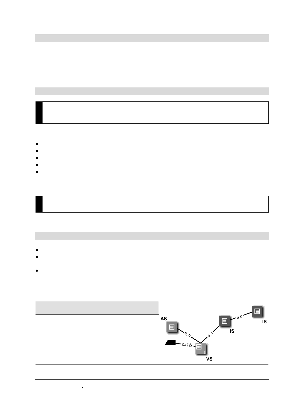
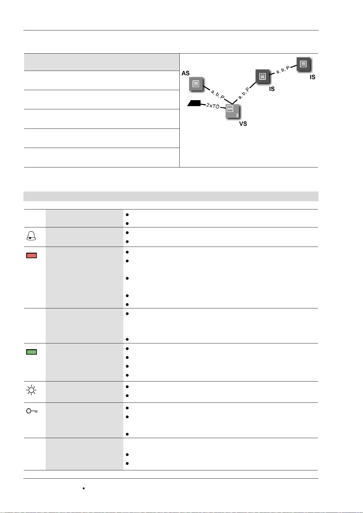
Wiring example.................................................................................................................9
Connection diagram 2-wire technique............................................................................10
Connection diagram 3-wire technique............................................................................10
Replace an ISH1030 or TTS1 through an ISH3130 .......................................................10
Commissioning................................................................................................................10
Settings.............................................................................................................................10
Preset times...................................................................................................................10
2-wire/3-wire operation...................................................................................................11
Ring tone selection.........................................................................................................11
Adjust the volumes.........................................................................................................11
Configuration options .....................................................................................................12
Programming with the Service Device TCSK-01............................................................12
General to the conduit in TCS audio systems...............................................................13
Principle loop resistance.............................................................................................13
Measurement loop resistance.....................................................................................13
Repair................................................................................................................................14
Fault detection and indication.........................................................................................14
Replace an indoor station –programme bell button.......................................................14
Cleaning............................................................................................................................15
Conformity........................................................................................................................16
Information on disposal ..................................................................................................16
Warranty...........................................................................................................................16
Spare parts, accessories.................................................................................................16
Service..............................................................................................................................16

07/2012 3
TCS TürControlSysteme AG Subject to technical changes.
E-Mail: hotline@tcsag.de www.tcsag.de PI_ISH3130-uk.doc 1A
Scope of delivery
1 x indoor station ISH3130: upper cover, lower cover, handset with handset cord
product information
instruction manual
Safety instructions
!
Attention! Installation, mounting, commissioning and repair of electrical devices have
to be carried out only by qualified electricians. The current standard for the installation
of door communication systems must be observed!
When installing TCS:BUS systems, the general safety regulations for telecommunication
systems according to VDE 0800 must be observed. Inter alia:
separated cabling of heavy and low current lines,
minimum distance of 10 cm for common cabling,
use of separators between heavy and low current lines in shared cable ducts,
use of standard telecommunication lines, e.g. J-Y (St) Y with 0.8 mm diameter,
existing lines (modernisation) with deviating cross sections can be used in compliance
with the loop resistance.
Installation –protective measures
!
With suitable requirements to protect against lightning, it has to be ensured that a volt-
age of each 32 V DC is not to be exceeded at the connections a, b, P, E.
Intended use
ISH3130 are door telephones for duplex communication with handset for the TCS:BUS.
They are suitable for the operation in TCS audio systems and combined audio/video
systems in the object area.
They are suitable for surface-mount (installation via flush-mounted socket) or desktop
mount with desktop accessory ZIT3030-0010.
Max. number of ISH3130 in 2-wire operation
when using power supply
and control unit
max. number
ISH3130
BVS20 or
NBV1000, 1 line
20
BVS100,
distributed to 3 lines
80
VBVS05, 1 line
30

4 07/2012
TCS TürControlSysteme AG Subject to technical changes.
E-Mail: hotline@tcsag.de www.tcsag.de PI_ISH3130-uk.doc 1A
Max. number of ISH3130 in 3-wire operation
when using power supply
and control unit
max. number
ISH3130
BVS20 or
NBV1000, 1 line
20
BVS100,
distributed to 3 lines
80
VBVS05, 1 line
90
BVS20 + NGV1011,
1 line
90
AS front-door station
VS power supply and control unit
IS indoor station
Note: The number of front-door stations which can be
connected is limited. Details are described in their
product information!
BVS100 + NGV1011,
3 lines
270
Indication and operating elements
handset
speaking to the door
end speaking
call OFF-button
shortly press: ring tone stopper
press for 8 sec: initiate ring tone selection
indication call OFF
(red)
is ON: call OFF is activated
flashes: ring tone stopper is deactivated, door release
automatic or call diversion is activated
flashing OFF: ring tone stopper is activated, door re-
lease automatic or call diversion is activated
error indication: both LEDs flashing
ring tone selection: both LEDs are ON
○
function key
control function 8,
alternate allocation can be activated: internal call, door
release automatic, call diversion
ring tone selection internal call
call indication
(green)
is ON: call, speaking is activated
blinks 3 x: voice channel is busy
error indication: both LEDs flashing
ring tone selection: both LEDs are ON
light button
switch lights
ring tone selection floor call (from the flat door)
door release button
open the door
trigger light switch function (if light switch function is
activated in the front-door station)
ring tone selection door call of the front-door station
volume control for
voice output and
ring tone
adjustable in 8 steps:
when voice communication is established
when the handset is cradled (no voice communication)

07/2012 5
TCS TürControlSysteme AG Subject to technical changes.
E-Mail: hotline@tcsag.de www.tcsag.de PI_ISH3130-uk.doc 1A
Device overview
Technical data
supply voltage: +24 V ±8 % (power supply and control unit)
housing: plastics white
dimensions (in mm): H 204 x W 100 x D 50
weight 340 g
acceptable ambient temperature: -5 ...+ 40 °C
degree of protection: IP30
input current in stand-by 2-wire operation: I(a) = 1 mA
3-wire operation: I(a) = 0.2 mA, I(P) = 1 mA
max. input current: I(Pmax) = 70 mA
handset
call indication (green)
indication call OFF (red)
call OFF button
light switch button
function key
ring tone loudspeaker
door release button
volume control
handset connection cord

6 07/2012
TCS TürControlSysteme AG Subject to technical changes.
E-Mail: hotline@tcsag.de www.tcsag.de PI_ISH3130-uk.doc 1A
Short description
large, deteched, blue door release button
light switch button
function key (fixed assignment with control function 8,alternate allocation can be acti-
vated: internal call, door release automatic, call diversion)
call OFF button for ring tone mute with optical indication
optical indication of door calls via LED (green)
optical display of a busy line when voice communication is established LED (green)
sending the sender serial number in case of internal calls
ring tones can be adjusted by residents, selection of 13 ring tones with improved quality
voice volume and ring tone volume can be adjusted in 8 steps from the user
acoustic call distinction between 2 front-door stations (via configuration software
configo™), flat door (floor door) and internal call
a parallel call can be activated (via Service Device TCSK-01 or configo™)
audio privacy function and automatic call cut-off
magnetic handset cradle
pluggable handset cord
lower cover with pined screw terminal can be pre-installed and can be equipped alterna-
tively with sister product for hands-free talking
optical (and acoustic) error indication
can be functional extended due to mounting places for call relays, activation radio signal
device and EnOcean radio interface
energy-efficient due to low stand-by consumption of only 0.025 W
Installation
Install lower cover
For placing the connection cables without any
problems, a flush-mounted socket must be in-
stalled behind the device.
Position the flush-mounted socket below the
cable conduit.
Install the lower cover with three screws.
TIPP: Avoid tearing of the straps:
For fixing at the straps do not use counter-head screws
rather use flat washers!

07/2012 7
TCS TürControlSysteme AG Subject to technical changes.
E-Mail: hotline@tcsag.de www.tcsag.de PI_ISH3130-uk.doc 1A
Connect the lines (2-wire technique)
Minimize the length of the lines above the
lower cover to place the lines without any
problems and do not clamp the lines when
snapping-on the upper cover.
Connect the lines according to the labeling:
a b E P (from the button to the top), floor
push button at a –E.
Wiring example see page 9.
Snap-on the upper cover
Set on the upper cover at both adjustment
increments of the lower cover (1).
Snap-on the upper cover below with slight
pressure (2)
Connect the handset
Plug the western connector of the handset
cord into the socket at the underside of the
telephone.
1
2
floor push button

8 07/2012
TCS TürControlSysteme AG Subject to technical changes.
E-Mail: hotline@tcsag.de www.tcsag.de PI_ISH3130-uk.doc 1A
Open the device
Remove the handset cradle.
There is a rectangular release opening at
the underside of the device. Insert a small
screwdriver straight and with slight pressure
into this opening.
The upper cover can be removed at the
underside (1).
Lift the upper cover out of the two upper
adjustment increments (2).
Installation of extended functions
TRE1*
radio transmitter board
FFS3100
radio interface FBI4200
The extended functions (and the antenna) have to be fixed in the indoor station with
adhesive pads (see also product information of each extended function).
* Connecting the lines is realised in analog to the ISH3030 (see product information TRE1-EB/1).
1
2

07/2012 9
TCS TürControlSysteme AG Subject to technical changes.
E-Mail: hotline@tcsag.de www.tcsag.de PI_ISH3130-uk.doc 1A
Connect the lines
Connection lines
acceptable cross-section (diameter)
0.08 … 0.82 mm2(Ø 0.32 … 1.0 mm)
max. number of wires per terminal contact
each 2 x 0.8 mm, 3 x 0.6 mm
!
Further wires have to be connected with auxiliar terminals!
!
Use only connecting lines with identical diameter in one terminal contact.
Wiring example
floor push
button
floor push
button

10 07/2012
TCS TürControlSysteme AG Subject to technical changes.
E-Mail: hotline@tcsag.de www.tcsag.de PI_ISH3130-uk.doc 1A
Connection diagram 2-wire technique
Connection diagram 3-wire technique
Replace an ISH1030 or TTS1 with an ISH3130
The floor push-button always has to be connected to the a-wire.
In case of a parallel connection, both telephones must be replaced with an ISH3130.
Commissioning
Install the devices of the system voltage-free and completely.
Check the a-, b- and P-wire against each other for short-circuits.
Switch on the main voltage.
Note:
If the floor push button does not work, check if it is connected to the a-wire of the power
supply and control unit.
Settings
Preset times
communication time
2 min
flashing period of the green LED, if the voice
channel is busy after lifting the handset
2 sec
3 x flashing
internal stand-by time, if the device is calling
or is called
around
30 sec

07/2012 11
TCS TürControlSysteme AG Subject to technical changes.
E-Mail: hotline@tcsag.de www.tcsag.de PI_ISH3130-uk.doc 1A
2-wire/3-wire operation
The jumper J1 is adjusted for 2-wire operation
in delivery state. J1
2-wire operation (state of delivery)
Install the jumper J1 at both upper contacts
for 3-wire operation.
3-wire operation
Ring tone selection
For 4 different incoming calls (door calls from 2 different front-door stations, floor call and
internal call) different ring tones can be selected.
1
End voice communication. Press call Off button for 8 sec. Both LEDs are ON and
an acknowledgement tone sounds, the ring tone selection is activated.
By pressing the following buttons, a ring tone can be selected. You can choose be-
tween 13 tones.
2a
select door ring tone
of the front-door sta-
tion*
Press the door release button until the required ring tone
sounds. The ring tone selected last will be stored.
2b
select door ring tone
of the floor door
Press the light switch button until the required ring tone
sounds. The ring tone selected last will be stored.
2c
select internal ring to-
ne
Press the control key until the required ring tone sounds.
The ring tone selected last will be stored.
3
Shortly press the call OFF button.
Or: If no button is pressed for around 8 sec, the device ends the ring tone selection
automatically. Both LEDs go out and an acknowledgement tone sounds, the ring
tone selection is deactivated.
* The ring tone is identical for all front-door stations and can be selected only identically for all.
To select a second ring tone it is necessary to activate the call distinction by changing the audio AS limit.
Changing the audio AS limit is possible only with the configuration software configo™.
Adjust volumes
Adjustable in 8 steps. A signal tone reproduces the adjusted volume when turning the ring
tone volume control. If the adjustment is finished, the adjusted ring tone sounds in the ad-
justed volume.

12 07/2012
TCS TürControlSysteme AG Subject to technical changes.
E-Mail: hotline@tcsag.de www.tcsag.de PI_ISH3130-uk.doc 1A
voice volume
Turn the ring tone volume control when a voice communication is
established (preset ex works: volume level 6 out of 8).
ring tone volume
Turn the ring tone volume control when the handset is cradled, no
voice communication (preset ex works: volume level 7 out of 8).
Configuration options
function
manually
TCSK-01
configoTM
as of version 1.6.x
ring tone volume
x
–
–
voice volume
x
–
–
select ring tones for door calls in-
ternal calls and floor calls
x
–
x
ring tone for door call 2
–
–
x
parallel allocation
–
x
x
control function 8 /internal calling /
call diversion / door release auto-
matic
–
x
x
floor door function* ON/OFF
–
–
x
send sender serial number in case
of an internal call
–
–
x
change audio AS limit
–
–
x
block ring tone output
x
–
x
block ring tone selection
–
–
x
unlimited communication time
–
–
x
reset to factory setting
–
–
x
* If the floor door release function in the EEPROM has been activated and the door release automatic function via
function key is switched on simultaneously, the control function 11 is send automatically when pressing the floor push
button. If the door release automatic is switched off, the standard floor door release function is realised when press-
ing the floor push button.
Programming with the Service Device TCSK-01
The indoor station is acting as a telephone.
Use the commands “8“ to make configurations (see product information Service Device
TCSK-01).
search telephones
switch on parallel call
switch off parallel call
Ser. no. = the serial number of the indoor station which is to be configured anew
ParSNo.= the serial number of the indoor station, to which the new configured indoor station is allocated to
0

07/2012 13
TCS TürControlSysteme AG Subject to technical changes.
E-Mail: hotline@tcsag.de www.tcsag.de PI_ISH3130-uk.doc 1A
General information on the conduit in TCS audio systems
The conduit is determined by structural conditions and is only limited by its length.
Observe when selecting the cables: the loop
resistance can amount max. 20 Ω(see table)
In compliance to the max. permitted loop re-
sistance the cross section can be doubled,
which means, that for one wire two lines can be
used (illustration). The lines have to be twisted.
When using shielded cables: connect the shield-
ing with each other and put it one-sided on mass
(b-wire) in the power supply
optional strand or star formed wiring
Table: loop resistances
cable length in m
cable diameter
0.6 mm
0.8 mm
loop resistance in Ω
10
1.28
0.71
20
2.55
1.43
30
3.83
2.14
40
5.10
2.86
50
6.38
3.57
60
7.65
4.29
70
8.93
5.00
80
10.20
5.71
90
11.48
6.43
100
12.76
7.14
150
19.13
10.71
200
25.51
14.29
250
17.86
300
21.43
Principle loop resistance
Measurement loop resistance
None of the devices (AS, IS or FE) should ever be
located more than 20 Ohm away from the power
supply and control unit (VS).
Switch off the 230 V / 50 Hz of the VS.
Install the a-b short-circuit at VS.
Other devices do not disturb the measurement,
they can stay connected.
Measure the resistance on a/b at the strand of the
last indoor or front-door station.
rd/bu wh/ye wh/gn wh/bn wh/bk

14 07/2012
TCS TürControlSysteme AG Subject to technical changes.
E-Mail: hotline@tcsag.de www.tcsag.de PI_ISH3130-uk.doc 1A
20 Ohm:
max. 160 m distance AS/IS-VS by 0.6 mm diameter
max. 300 m distance AS/IS-VS by 0.8 mm diameter
AS front-door station
VS power supply and control unit
IS indoor station
FE extended function
Repair
Error detection and indication
Errors are signalled optically and acoustically: constant flashing and when pressing any
button, an error tone sounds. The optical error indication stays active until the error is cor-
rected.
error causes
display
erro
mode
error tone
elimination
a- and P-wire are inter-
changed or short-circuited
both
LEDs
flash
change a- and P-wire or eliminate short-circuit,
device is in stand-by mode again
a-wire: not connected or
not supplied
connect the a-wire or check power supply,
device is in stand-by mode again
button stucks
(press longer than 15 sec)
remove button at the device or loosen floor push but-
ton, device is in stand-by mode again
Exchange an indoor station –programming bell buttons
Basics
All devices at the TCS:BUS have got an unique serial number.
Programming a bell button means that the serial number of an indoor station is allocat-
ed to the bell button of a front-door station and is stored within the EEPROM of the
front-door station.
Ensure that the new indoor station is connected to the TCS:BUS and the mains voltage
is switched on (the operation LED at the power supply and control unit is ON) and fur-
ther, that the access to the flat is granted during the programming.
This instructions describes the case that a serial number is allocated to the bell button
without setting a programming lock. To neutralise a programming lock you need a Ser-
vice Device TCSK-01or the configuration software configo™.
a, b short-
circuit here

07/2012 15
TCS TürControlSysteme AG Subject to technical changes.
E-Mail: hotline@tcsag.de www.tcsag.de PI_ISH3130-uk.doc 1A
1
Initiate
power supply and control unit
RUN/PROG push
button: shortly press LED blinks
Programming mode of the system is switched on
2
Delete a buttona)
Press until the delete-tone-melody sounds 1)
release
3
programming via voice connection
oder
establish voice connection
to the front-door station 2)
shortly press
the button
... a ring tone sounds at the front-door
and indoor station 1)
4
End
power supply and control unit
RUN/PROG push
button: shortly press LED is ON
programming mode of the system is switched off *)
a) Not necessary, if the bell buttons have not been programmed, comp. product information of the front-door station.
1) If there sounds a Progsperr tone instead, the front-door station is equipped with a programming lock.
The programming lock can be deactivated only with the Service Device TCSK-01 or the configuration software
configo™.
2) New developed front-door stations (as of 2009) respond to that with a positive acknowledgement, if the serial number
of the indoor station was received (see product information of the front-door station).
*) for device specific indication modes of the front-door station see product information of the front-door station
Cleaning
!
Avoid water from entering the device!
Do not use any abrasive detergents!
Clean the device with a dry or slightly moist cloth.
Remove stronger stains with a mild plastic cleaner.

16 07/2012
TCS TürControlSysteme AG Subject to technical changes.
E-Mail: hotline@tcsag.de www.tcsag.de PI_ISH3130-uk.doc 1A
Conformity
Declarations of conformity are available under www.tcsag.de, Downloads, trade
information.
Information on disposal
The adjoining symbol shows that the device has to be disposed separately from
domestic waste. The materials used are recycable. Please do help protecting out
environment and dispose the device via a collection point for electronic scrap.
Dispose the parts of the packaging in collecting tanks for cardboard and paper
resp. plastics.
Warranty
We offer a simplified processing in case of warranty for electricians.
Note our conditions of sale and delivery for download from www.tcsag.de, Down-
loads, trade information.
Spare parts, accessory
short text
article number
10 x lower cover ISx3xxx-x140
E32431
10 pieces cover panel white 120 x 250 x 2 mm
E24340
Service
Please send your questions and inquiries to
headquarters
TCS TürControlSysteme AG, Geschwister-Scholl-Str. 7, 39307 Genthin
www.tcsag.de
Table of contents
Other TCS Telephone manuals