TCT Solar PROGRESSIV TUBE User manual

OPERATIONS MANUAL
PROGRESSIVTUBE
®
Passive Solar Water Heater
INSTALLATION
and
INSTALLING CONTRACTOR:
A Factory Direct Distributor
of Solar Thermal Products and Equipment
6935 15th St E, Suite 120 - Sarasota FL 34243
Phone 941-360-9276 • 941-359-3848 Fax
tech@solardirect.com
www.shop.solardirect.com

TABLE OF CONTENTS
I. Introduction
II. Utilization
III. System Characteristics
IV. Pre-Installation Check List
V. Installation Precautions
VI. Collector Orientation
VII. Collector Mounting Hardware Options
VIII. Roof Mounts
A. Load Bearing and Bracing
B. Roof Piping and Penetrations
C. Roof Mount Penetrations
D. South/North Roof Mounts
E. East/West Roof Mounts
F. Tile Roof Installations
1. On Top of Tile
2. Flush To the Roof
IX. Ground Mounts
X. System Plumbing
XI. System Insulation
XII. Freeze Prevention
XIII. Two or More collector Systems
XIV. Direct Systems
XV. Start Up Procedures
XVI. Drain Procedures
XVII. Maintenance and Operation
APPENDIX
SRCC Section
FSEC Section
INSTALLATION DETAILS
TYPICAL ROOF BRACING
YOUR NOTES
Please read and understand Installation and Operations Manual and safety
messages before installing, operating or servicing this solar water heater. Failure
to follow instructions and safety messages could result in death or serious injury.
2

FLOW PATTERN
The PROGRESSIVTUBE®solar water heater works simply on sunlight and your local water
pressure. There is no electrical energy needed to make it function. Once the system
has been filled, it will operate on main water pressure or flow rates that are normal to
your household. The simple design and quality construction of the solar collector will
provide you with years of energy saving, trouble free operation.
HOT OUT
COLD IN
COLD OUT
INSULATED PIPE
HOT OUT
The solar energy systems described by this manual, when properly installed and maintained, meet the minimum
standards established by the Florida Solar Energy Center, in accordance with Section 377.705, Florida Statutes.
This certification does not imply endorsement or warranty of the product by the Florida solar Energy Center of the
State of Florida.
3

PROGRESSIVTUBE®
INSTALLATION MANUAL
I. INTRODUCTION
This installation manual is intended to provide the requirements, recommendations, and
guidelines necessary to achieve simplified installation and years of trouble free system
operation. There are many ways to plumb a PROGRESSIVTUBE®system, but only the methods
included in this manual are endorsed by the manufacturer. The pre-heater system designs in
this manual meet the Florida Solar Energy Center’s (FSEC) Approved Systems review and
certification program, and/or the Solar Ratings and Certification Corporation’s (SRCC) Certified
Solar Collector and Water heating System Rating and Standards program. All
PROGRESSIVTUBE®models have an approved listing by the International Association of Plumbing
and Mechanical Officials (IAPMO).
The FSEC Approved Systems are called “two-way systems” and the proper plumbing schematic
should be followed depending upon whether a conventional gas, electric or instantaneous water
heater is used for back up. A “two-way” system can function in one of two ways; either as a
solar pre-heater to the conventional gas, electric, water heater or as a conventional water heater
only with the PROGRESSIVTUBE®collector by-passed.
The SRCC certified OG 300 system is a “three-way” system designed for use with either a
gas or electric conventional water heater. A “three-way” system can function in any of the three
following modes: solar pre-heat, solar by-pass, or solar direct. The solar direct mode feeds
solar heated water directly to the household from the PROGRESSIVTUBE®unit allowing the
conventional water heater to be by-passed and turned off. This mode allows homeowners to
maximize their savings during peak solar collecting months, usually spring through fall. To meet
all requirements of the SRCC OG 300 system, please refer to the SRCC section in the
Appendix.
Note: In the case of the installation of the PROGRESSIVTUBE®with an instantaneous water heater,
the installer should follow the instantaneous water heater manufacturer’s installation instructions
The procedures in this manual are for all PROGRESSIVTUBE®Passive Solar Water Heater
models. The only difference in the four available models is the amount of water each one holds:
PT-20-CN, 20 gallons, PT-30-CN, 30 gallons, PT-40-CN, 40 gallons and PT-50-CN, 50 gallons.
All models have a 25-year design life.
4

II. UTILIZATION
PROGRESSIVTUBE®Passive Solar Water Heaters are designed as self-contained units that act
as a solar collector and storage tank integrated into one piece of equipment. In most cases,
they are utilized as a pre-heater to a conventional water heater; however, they can be installed
as direct solar water heaters. The unit can also be used as a pre-heater for a terminal or
instantaneous water heater. If a PROGRESSIVTUBE®unit is installed to a terminal or
instantaneous water heater the procedures and plumbing schematics for either the two-way or
three-way system should be followed. Make certain the instantaneous tankless water heater
has a temperature limiting device. Many electric models do not include this safety device and
should be avoided.
PROGRESSIVTUBE®systems are designed to operate automatically. However, as with all solar
water heating systems, the total amount of solar contribution by the system is dependent upon
the hot water consumption pattern of the household, daily weather conditions, and variable
amounts of available sunlight throughout the year. Energy savings will vary from month to
month, but it is possible to maximize these savings by scheduling large hot water usage, such
as clothes and dishwashing, for the early afternoon.
The simple design and quality construction of PROGRESSIVTUBE®will ensure a reliable service
life of twenty-five years or more. This manual details the essential operation of the system and
is intended to illustrate proper installation techniques. To ensure trouble free operation, all
installation work should be performed by qualified licensed contractors and in accordance with
all local codes.
III. SYSTEM CHARACTERISTICS
All PROGRESSIVTUBE®Passive Solar Water Heaters are designed to efficiently collect solar
radiation and to convert it into usable energy for household or business hot water usage. Do not
use PROGRESSIVTUBE®units for heating or storing anything except POTABLE water.
The PROGRESSIVTUBE®system is a passive system because it has no moving parts and
operates on local water pressure and solar radiation. There are no pumps or controls to
maintain and no electrical energy is required to make it function. Once the system has been
filled, it will operate at the flow rates that are normal to the household.
The collector/storage tank of the unit absorbs solar radiation through its highly selective surface
that raises the temperature of the water stored in the collector. Water flows through the cold
water supply line into the lowest tube of the unit. The tubes in the PROGRESSIVTUBE®are
connected in series so that the top of the lower tube feeds the bottom of the next tube. This
flow configuration ensures the delivery of the hottest water for each usage.
The colder replacement water is contained in the lower tubes where it is heated by the sun.
When hot water is used in the household, solar preheated water is drawn into the conventional
water heater, reducing or eliminating electricity or gas usage for heating water. (A direct solar
system does not use a conventional water heater. Hot water flows directly from the unit to the
point of use).
5

2–WAY SYSTEM FOR ELECTRIC WATER
HEATER
COLD
HOT
MIX
8
7
6
5B
5A
432
Hot Water
Out
Cold Water
In
Cold Water
Inlet
Hot Water
Outlet
1
9
11
9
inlet
outlet
10
2-WAY SYSTEM FOR GAS WATER HEATER
8
7
6
5B
5A
4
3
2
Hot Water
Out Cold Water
In
Cold Water
Inlet
Hot Water
Outlet
1
9
COLD
HOT
MIX
11
9
inlet
outlet
10
DIRECT SOLAR SYSTEM
COLD
HOT
MIX
1
4
8
5A
Hot Water
Out
Cold Water
In
11
inlet
outlet
5B
10
SRCC OG 300 3-WAY SYSTEM
9
11
9
inlet
outlet
COLD
HOT
MIX
8
7
6
5B
5A
4
3
2A
Hot Water
Out
Cold Water
In
Cold Water
Inlet
Hot Water
Outlet
1
2B
10
2-WAY SYSTEM FOR TANKLESS WATER
HEATER
7
6
5B
5A
4
3
2
Hot Water
Out
Cold Water
In
Cold Water
Inlet
1
9
COLD
HOT
MIX
11
9
inlet
outlet
8
10
ITEM LIST
1- Supply shut off valve
2- 3-way Ball Valve
3- 2-way Ball Valve
4- Tempering Valve or Mixing Valve
5- Boiler Drains
6- Pressure Relief Valve
7- Water Heater
8- Pressure Relief Valve
9- Roof Flashing
10- Vacuum Breaker
11- PROGRESSIVTUBE®
6

IV. PRE-INSTALLATION CHECK LIST
1. Check local codes for plumbing and roof load requirements. Installations must meet all
local code requirements for penetrating structural members and fire rated assemblies.
2. Obtain all applicable permits.
3. Inspect the roof. If it is in poor condition, advise the homeowner before the installation
is begun.
4. Properly plan the installation by inspecting the attic and location of the conventional
water heater. Discuss the proposed location of ht system’s major components with the
homeowner to avoid any possible conflicts.
5. Make sure you have all necessary materials at the job site before starting the
installation. Proper planning reduces labor and material costs.
6. PROGRESSIVTUBE®Solar Water Heaters are designed for POTABLE WATER use only.
The collector/storage tank is constructed of copper alloy. Each shipment of material
shipped to TCT SOLAR is certified to be greater than 99.05% pure copper. This alloy is
the ANSI and ASTM standard for potable water piping. TCT SOLAR’SWarranty on
corrosion specifically states the “water must meet EPA Standards of Potable Drinking
Water and have a PH maintained between 7.0 and 9.0 at all times”. Some areas may
not have water quality that meets these warranty criteria. If water is too acidic, “pitting
corrosion” can occur. If the situation is prolonged, the corrosion action can result in “pin-
hole” leaks in the tubes. Pitting corrosion is always clear indication of aggressive water.
If there is a concern for water quality and the ability to maintain proper PH levels then
measures should be taken to properly condition the water before it enters the
PROGRESSIVTUBE®. Water softener/conditioners work very well to relieve this problem.
If the situation cannot be resolved, then considerations should be taken as to whether
the installation should proceed.
V. INSTALLATION PRECAUTIONS
The following are important measures to follow to ensure a safe, trouble free installation.
1. Remove the temporary labels after installing the unit (i.e., “In”, “Out”, and “Do Not
Use Pipe Connections for Handles”).
2. Remove the plastic pipe caps before exposing the unit to full sunlight; otherwise
they may melt onto the inlet and outlet nipples.
3. Be careful of the inlet and outlet nipples during installation. The unit can dry
stagnate up to 4000F causing the nipples to produce severe burns if touched.
4. Do not lift or handle the unit by the copper inlet and outlet nipples. You could crack
a weld and cause the unit to leak. This is not covered by the warranty. Each
unit is pressure tested to 165 psig during manufacturing and again at 50 psig before
shipment.
7

5. Use 95/5 or 60/40 lead free solder for the collector piping because of the high
temperature stagnation of the unit.
6. Keep the collector covered during installation. Even early morning sun can quickly
heat up the absorber. It is most important that the unit be vented to the atmosphere
before and while being filled. It is recommended that the collector be filled before
soldering the return piping to the collector outlet, or open the pressure relief valve or
open the boiler drain on the return line, or in some other fashion make sure the unit
is vented to the atmosphere. Failure to follow these instructions will void the
warranty and could damage the unit.
7. The collector should stagnate wet (filled) during times of non-use, except during
severe winter conditions where temperatures are below 100F. Under these
conditions the collector and the solar loop piping should be drained.
8. Remember, the collector can easily produce 180°F to 200°F water during clear,
sunny weather.
VI. COLLECTOR ORIENTATION
The installation site of the collector should be chosen so the unit receives maximum solar
exposure. It should never receive more than 10% shade on the collector absorption surface
between 10:00 a.m. and 3:00 p.m. The location should be as close as possible to the
conventional water heater to minimize the piping run, which should not exceed 75 feet.
For optimum performance in the northern hemisphere, the collector should face due south.
Slightly decreased but good performance can be expected from a collector facing within 450of
due south. In the southern hemisphere the opposite direction, due north, is faced for optimum
performance.
The unit tilted to local latitude in Sunbelt areas will produce the best overall performance. (This
rule of thumb should also be followed for installations in tropical zones such as the Caribbean).
Increasing the tilt 100to 150in the Sunbelt will improve winter performance. In areas above the
Sunbelt, the tilt for best year round performance is latitude plus 100to 150. These parameters
are valid in both northern and southern hemispheres.
VII. COLLECTOR MOUNTING HARDWARE OPTIONS
There are three mounting hardware options.
Adjustable Tilt Mount (Drawing B)
Fixed Mount (Drawing A)
Flush Mount (Drawing C)
Choose the hardware system best suited for the particular installation.
The chart on page 11, “Mount Dimensions and Angles” gives the tilt angle of the collector for
the various Standoff lengths that are used with the Tilt Mount hardware. The chart also gives
the width distance between roof penetrations for the Fixed and Flush Mount sets.
8

COLLECTOR MOUNTING OPTIONS
Drawing A - Fixed Mount
For installation parallel to the roof PTMS
PTMS Part List
A) Clamps: Qty 4
B) Mounting Brackets: Qty 4
C) 3/8”x 1” Hex Head Cap Screws: Qty 4
D) 3/8”X 2 ¼” HEX HEAD CAP SCREWS: QTY 4
E) 3/8” Lock Nuts: Qty 8
F) CROSS CHANNELS: QTY 2
9

Drawing B - Adjustable Tilt Mount
For Installation with additional angle of the roof or ground mounting
Include Standoff Rear Legs-STS
STS PART LIST
G) Rear Leg Sq. Tube
1 ft, 2 ft, 3 ft or 4 ft sq tube
NOTE: STANDOFF REAR LEGS
INCLUDE
H) 3/8”x 2 ¼” Hex Head Cap Screws:
Qty 2
I) 3/8” Lock Nuts: Qty 2
10

Drawing C - Flush Mount
MOUNT DIMENSIONS AND ANGLES
Collector Standoff Dim “A” Angle
PT-20-CN 1 Foot 29 1/8” 26º
PT-20-CN 2 Foot 4 7/8” 85º
PT-30-CN 1 Foot 35 5/16” 17º
PT-30-CN 2 Foot 29 1/8” 38º
PT-30-CN 3 Foot 12 5/8” 70º
PT-40-CN / PT-50-CN 1 Foot 47 ¾” 13º
PT-40-CN / PT-50-CN 2 Foot 43 5/16” 28º
PT-40-CN / PT-50-CN 3 Foot 34 ½” 45º
PT-40-CN / PT-50-CN 4 Foot 14 5/8” 72º
Dim “A”
Collector Dim “B”
PT-20-CN 23 ¾”
PT-30-CN 36 7/8”
PT-40-CN / PT-50-CN 48 7/8” Dim “B”
11

VIII. ROOF MOUNTS
The structure of the roof should first be examined to determine the dimensions of its members.
Check applicable codes as to loading requirements. The roof penetrations should be located
over an attic or similar space that is not blocked by a chimney, beams, or other obstacles.
Preparation of the roof area and procedures for anchoring to the roof members must be done
carefully to avoid causing leaks or weakening the roof. In a new home installation, much of the
mounting work can be performed after the roof has been framed and sheathed. In some cases,
such as built-up roofs, the mounting work can be performed before the waterproof membrane is
applied. On tile roofs, the mounting work is best performed after the waterproof membrane is
applied, but before the tiles are laid.
The PROGRESSIVTUBE®was specifically designed for maximum performance and draining when
mounted horizontally. A level horizontal position is the only acceptable mount for installations
above latitude 400. Installing a unit in a vertical position is not recommended. If a unit is
installed vertically there will be considerable air entrapment within the absorber/storage tank
and, once filled, it is very difficult to drain.
A collector is exposed not only to sunlight and its destructive ultraviolet radiation, but also to
wind forces. Collectors installed in areas that experience hurricane force winds are particularly
challenged. Florida codes require that a collector and its mounting structure be able to
withstand intermittent wind loads up to 140+ mph. PROGRESSIVTUBE®units and mounting
hardware have been wind load tested to 180 mph and hundreds of units have survived storms
with winds in excess of 180 mph. The structural integrity of a collector is most important when
considering long-term performance.
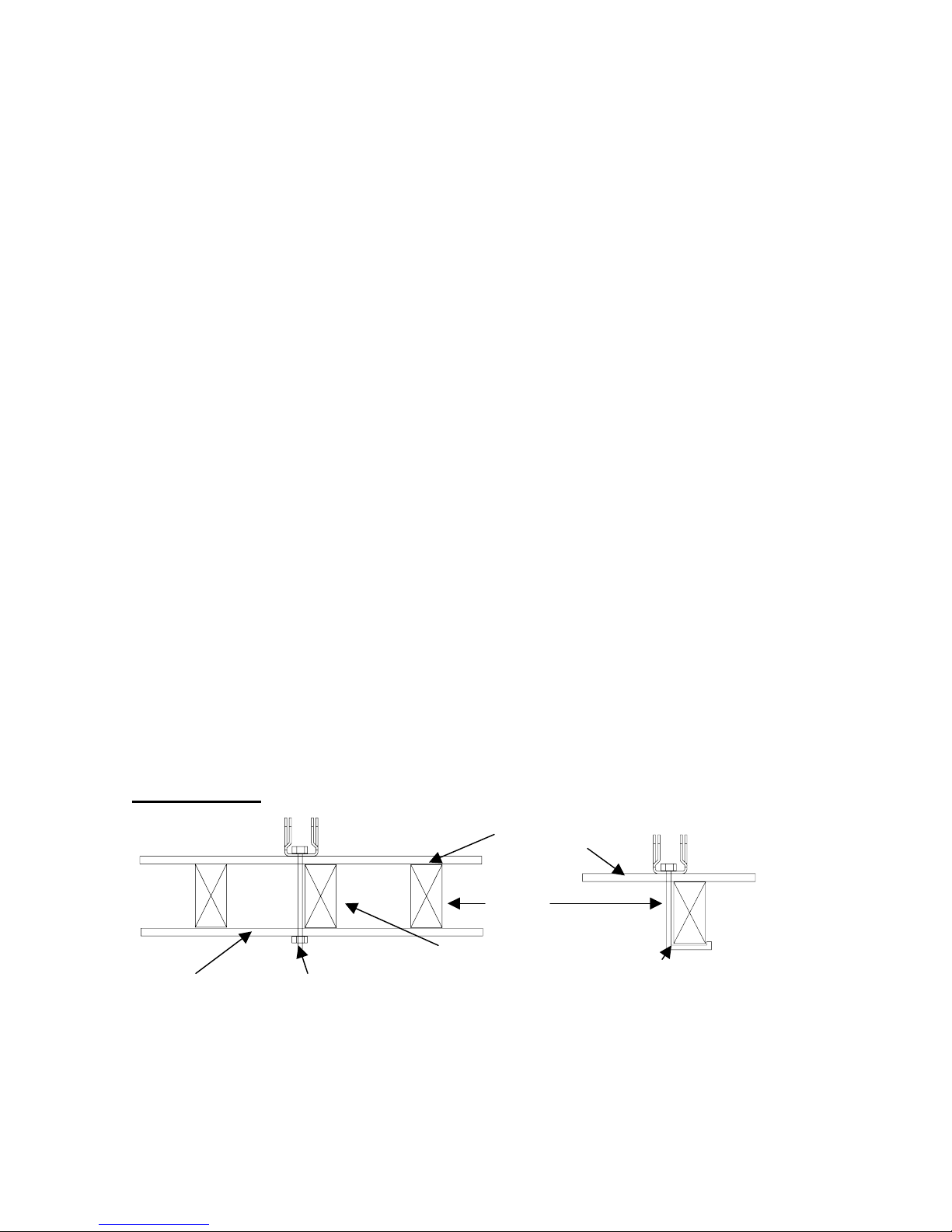
A. Load Bearing and Bracing
Whenever possible, mount the collector over a load-bearing wall or near the peak of the
pitched roof (usually within 15” of the roof crown). If neither of these sites are practical
and the collector must be installed on an open span of roof, extra means must be
employed to ensure a safe, proper installation. If the roof structure is of a 2”x4” truss
design, spread the load over at least five trusses and reinforce, or brace all truss
members where needed to comply with local building codes. See the Typical Roof
Bracing drawings in the Appendix for suggested roof structure bracing.
Note: When filled, a single PROGRESSIVTUBE
®
collector can weigh between 240 lbs and
665 lbs. Do Not mount the collector without adequate support as determined by
applicable building codes and sound building safety practices.
B. Roof Piping and Penetrations
It is best to locate pipe penetrations through the roof as close to the collectors as
possible. In some cases it may be possible to pipe both the supply and return lines
through the same penetration.Piping through the roof must be weather proofed.
Usually, a hole is drilled in the roof large enough for the copper pipe to pass through. A
standard plumbing roof vent stack flashing cover is placed around the hole with its base
cemented to the roof using appropriate roof caulking such as polyurethane. Slide its
upper edge under the adjoining shingle. Caulking is then placed in the top and around
the copper pipe and insulation. A “coolie cap” can be fashioned, see Drawing D,to
12

provide a waterproof seal. Another method is to make a flat copper flashing with an
oversize tube, which is penetrated by the copper water pipe. A coolie cap is made from
a reducing coupling that fits the oversized copper tube and is large enough for the
copper water pipe to just pass through. It is then soldered to the oversized copper tube
and the copper water pipe. See Drawing E. Make sure the pipe penetrations are
downhill from the collector connections. Water will not drain uphill.
DRAWING D
COPPER PIPE
SHINGLE
INSULATOR
CAULKING SHEATHING
COOLIE HAT
ROOFING FELT
C. Roof Mount Penetrations
Roof penetrations for mounting the collector can be any of the methods shown in
Drawing F. Appropriate waterproofing methods must be used. It is recommended to
use pitch pans, mounting blocks, or flashing under the universal mounting bracket and
DRAWING E
COPPER COOLIE HAT
(SOLDERED TO THRU PIPING) FLAT CLOPPER FLASHING
TO THE
COLLECTOR(S)
INSULATION
PENETRATION
USING FLAT
FLASHING
SEALANT
13
roofing material. Weather proof with appropriate sealant. Consult the waterproofing and
roof attachment drawings Details Q – Z in the Appendix for additional details.
In retrofit situations, rafters or roof trusses may be located from inside the attic if the
crawl space is large enough to permit access. Small galvanized nails may be driven up
beside the rafters at the desired anchoring point; this locates the penetration points for
the installers on the roof. Measure and mark the four roof penetration points for the
mounting bolts.
If access to the attic is not adequate, trusses can be located by looking or nails in the
facia board. They show the location and spacing of the trusses. Locate the mounting
points by measuring across the roof ridge and popping a chalk line between the ridge
and the facia along the run of the truss see Drawing G. The may not be perfectly
straight, so the chalk line will be close to, but not precisely on, the truss run. Many
installers use the variation in tone associated with external hammer blows to locate the
run of the truss.
Most roofs are either asphalt or fiberglass shingles. They are stapled or nailed in an
overlapping pattern over the felted plywood that comprises the roof sheathing. Old
brittle asphalt shingles may break underfoot. Use care until the condition of the shingles
is determined. Mount bases can be installed directly over pliable shingles; no special
preparation is necessary. Holes for the anchoring bolts should be drilled through the
shingles. The penetration holes should be completely encircled with roof sealant to
provide a watertight seal.
Roofs with hard, non-flexible shingles such as cedar shake and asbestos should be
treated the same as tile roofs.
Standing seam metal roofs are treated much the same as flexible shingle roofs. The
mount bases can be installed directly over the metal sheathing. On corrugated metal
roofs the penetrations must be made on the crown of the corrugation, never in the valley.
Special care must be taken when sealing this type of roof.
DRAWING F
TYPE 2
TYPE 1 ROOFING
MATERIAL
RAFTER
2”X4” CROSS
BRACE SPACER TO MATCH
RAFTER 3/8” J BOLT
3/8” NUT AND BOLT
OR THREADER ROD
14

TYPE 3 TYPE 4
3/8” THREADED ROD
WITH NUTS AND
WASHERS
D. South/North Roof Mounts
Most homes have a south facing roof. This roof area should be utilized for the collector
location unless there are shade or aesthetic problems. Follow the guidelines in Section
VI Collector Orientation, while taking into consideration the appearance of the system on
the home. Homeowners prefer systems that are not obtrusive and blend in with the
general architectural lines of the home.
Either the Fixed Mount or Flush Mount hardware systems are used for this situation.
The collector is installed parallel to the plane of the roof and the edge of the collector
should be in parallel with the roof ridgeline. The Fixed Mount system raises the
collector approximately 2.5 inches above the roof to allow air to circulate under the
collector and to prevent debris from accumulating along the top of the collector. If using
DRAWING G
ROOFING
MATERIAL
RAFTER OR
MATCHING SLEEPER ¼” X 1” STEEL
STRAP (MIN.)
PITCHPAN OR OTHER WATERPROOFING METHODS NOT
ILLUSTRATED
3” PENETRATION MIN.
AIN RAFTER WHEN
USING LAG BOLTS
A METHOD OF LOCATING MOUNTING POINTS
4. POP A CHALK LINE DOWN ROOF ALONG
TRUSS. 5. MEASURE TO ACTUAL MOUNTING
POINTS AND PREPARE ROOF SURFACE.
3. MEASURE TO
APPROXIMATE TRUSS
POSITION ALONG
ROOF RIDGE.
ROOF RIDGE
FASCIA
1. LOCATE NAILS IN FASCIA EITHER VISUALLY OR
WITH STUD FINDER (TRUSSES ARE USUALLY
MOUNTED ON 2-FOOT CENTERS). 2. CHOOSE MOUNTING TRUSSES.
15

the Flush Mount system, 2” x 6” pressure treated lumber blocks or exterior grade
material are used to create the air space under the collector. See Drawing C. To avoid
potential roof damage from mildew and rotting it is not recommended for the collector to
sit directly on the roof surface.
Sometimes the collector cannot be installed on the south-facing roof. An alternative is to
use a Reverse Pitch installation See Drawing H. The adjustable tilt mount hardware
system is used with extra long standoffs. Usually, three-foot standoffs are adequate for
PT-20-CN, PT-30-CN units and four-foot standoffs for PT-40-CN, and PT-50-CN units.
DRAWING H
REVERSE PITCH
COLLECTOR TILTED TO LOCAL LATITUDE
ANGLE “A”
SOUTH FACING ROOF
N
ORTH FACING ROOF
STANDOFFS SHOULD BE ANCHORED ON THE ROOF WITH THE DEGREE AT
ANGLE “A” BEING LESS THAN 75 DEGREES.
E. East/West Roof Mounts
Homes that do not have an acceptable south facing or reverse pitch location or that have
only north/south roof ridge line must use the Adjustable Tilt Mount system. The mounts
are anchored to parallel rafters and the collector is installed perpendicular to the roof
plane, facing south, at an angle equal to local latitude. This installation is sometimes
referred to as a “sawtooth position”.
For east or west facing roofs, the piping connections should always face downwards see
Drawing I. When installed on a west roof, the inlet pipe will become the outlet pipe and
visa versa. The west roof installation will result in slightly reduced performance, some
air entrapment and will only partially drain; therefore, this installation should only be used
if no other position is available. The west roof installation position should particularly be
avoided in severe freezing climates. In moderately freezing climates a freeze prevention
valve must be used on east and west roof installations. East roof installations will have
no air entrapment or loss of performance. A collector on an east roof will drain most of
the water in the tank, but the greater the slope of the roof the more water retained in the
tank. The collector must not be mounted on an east or west sloping roof that has a pitch
greater than 350.
16

DO NOT MOUNT THE UNIT VERTICALLY
EAST SLOPEWEST SLOPE
DRAWING I
F. Tile Roof Installations
PROGRESSIVTUBE®collectors are easily installed on tile roofs or flush to the roof with the
tile abutted to the collector. Installation Details Q and Z in the Appendix illustrates
these two methods. For anchoring the collector to the roof, the Spanner Mount Detail Q
is recommended. This technique allows for greater placement flexibility.
Tile roofs require more preparation than shingle roofs. When walking on these roofs,
care must be taken not to break the tiles or slip on loose ones. Never walk on the
crowns of barrel tiles. Broken tiles must be repaired with roofing adhesive or replaced.
This can increase installation time and cost. Tiles in the area of the intended mounting
penetrations may be broken up with a hammer and removed, or for a cleaner and
quicker installation, sawed out. Remove as few tiles as possible, because the area must
be totally sealed upon the completion of the mount bracket installation to protect the
underlying waterproof membrane. When the tiles are removed, the exposed waterproof
membrane may be treated as if it were a shingle roof. The broken tile may be replaced
with colored cement molded to look like the unbroken tile or a tile may be sized to cover
the mounting hardware base and anchoring bolt.
1. On Top Of Tile
The following basic procedures should be followed when installing the collector
on top of an existing tile roof. These procedures apply to both flat and barrel tile.
a) Determine the exact location on the roof where the four collector mounting
hardware roof penetrations are to be made.
b) Carefully remove one or two tiles at each location. If the tiles are “mudded” to
the weatherproof membrane, be sure not to tear or otherwise compromise the
integrity of the membrane.
17

c) Clean off each location of all membrane grit, dirt, and tile debris.
d) Drill the four penetration holes into the roof. If using lag bolts, be sure the
starter holes are in the center of the rafter. Because of the added difficulty of
installing on tile roofs it is sometimes much easier to use a spanner mount
across the rafters. See Detail Q for proper spanner installation.
e) Seal the roof penetration holes by liberally encircling the holes with
polyurethane or butyl rubber caulking compound.
f) Spread a thick coating of caulking compound on the bottom of the J-Bracket
so it will be completely covered when set in place and bolted to the roof.
Caulking compound should seep out all along the bottom edge of the J-
Bracket as the anchoring bolt is tightened into place.
g) After the J-Bracket is securely fastened to the roof, cover the head of the
anchoring bolt and the entire back portion of the J-Bracket with caulking
compound.
h) Replace as much tile as possible over the J-Bracket base as shown in Detail
F. A saw may be needed to cut the tile the proper length. After sizing the
tile, slide the back of it under the first tile above the J-Bracket. Be sure to
apply generous amounts of caulking compound between the sized tile, the
roof and the J-Bracket. The sized tile should overlap the anchoring bolt and
as much of the J-Bracket as possible.
i) Once all four J-Brackets are secured, caulked and re-tiled, they are ready for
the mount bases to be bolted on. Proceed with the remainder of the
hardware installation.
2. Flush To The Roof
PROGRESSIVTUBE®collectors can be installed flush to the weatherproof
membrane of a tile roof if a watertight seal can be formed between the bottom of
the collector and the membrane.
The following basic procedures should be followed when installing the collector
flush to the roof. These procedures apply to both flat and barrel tile.
a) Place the collector on the membrane in the exact location it will be anchored.
b) With a carpenter’s pencil or other suitable marker, trace the outline of the
collector onto the membrane. Do not use a sharp instrument, which might cut
into the membrane.
c) Move the collector aside.
d) Place Jiffy Seal 500, 6” wide sealing compound over the collector outline.
Start at the top of the collector outline and lay the strips.
e) Be sure the strips overlap the collector outline by at least 1 ¾”.
18

f) Remove the clear plastic protective lining on the Jiffy Seal. Lay the exposed
side of the sealing compound on the membrane and press into the roof with
palms of hands.
g) After all four strips have been laid into place, use a rubber mallet and firmly
hammer the entire strip down.
h) Remove the white paper protective lining of the Jiffy Seal.
i) Carefully place the collector on the sealing strips. Once in the desired
location, press the collector into the sealing compound.
j) Anchor the collector with the Flush Mount hardware. The Flush Mount clamp
should have the overlap of the sealing compound completely beneath it so
that a ½” or more of compound is exposed at the end of the clamp.
k) Once the collector is anchored, complete the piping connections.
l) Carefully notch-out the seal compound for the pipes if necessary. A flat, even
surface is necessary to properly seal the piping and pipe roof jacks.
m) Use a mallet and firmly hammer the sealing compound overlap all around the
collector to ensure a tight seal. Fill any gaps in the seal with caulk.
n) The tile can now be set flush to the collector. Caulking can be used to fill any
gaps between the collector and the tiles.
IX. GROUND MOUNTS
Ground mounted systems are the fastest and simplest installations. A ground mount must have
a stable, permanent foundation. A concrete HVAC pad or four standard concrete piers
embedded at least halfway in the ground are the recommended foundations see Drawing J.
Be sure to coat the threaded end of the bolts that secure the collector base mounts with
silicone caulk to prevent rust.
The lower edge of the collector should be at least one foot above the ground, so it will not be
obstructed by vegetation or partially submerged in standing water. Collectors mounted at
ground level can be more susceptible to damage (flying rocks from lawnmowers, etc) or
vandalism. The placing of an expanded metal mesh screen in front of the glass may be helpful
in preventing breakage.
In ground mount systems, if the collector is lower than the auxiliary tank within the house, then
the solar loop piping must slope downward from the house to the collector (or piping can be
buried in the ground running horizontally).
A boiler drain must be installed in all ground mounts at the collector inlet. A boiler drain or a
vacuum breaker must be installed at the collector outlet. Buried piping must be properly
insulated (min. ¾” wall) and non-degradable. In areas where severe freezing occurs, all
underground piping must be below the frost line and insulated with a minimum 1-1/2” wall
insulation see Drawing K. For ground mount systems that have two or more collectors, a boiler
drain must be installed at the inlet connection of all units and a vacuum breaker or boiler drain
must be installed at the outlet of each unit.
19

DRAWING J
RECOMMENDED FOUNDATION FOR
GROUND MOUNT INSTALLATION
FRONT VIEW
STANDARD CONCRETE PIER 50” TO 60”
48” TO 50” FOR PT-40-CN AND PT – 50-CN
36” TO 37” FOR PT-30-CN
22” TO 23” FOR PT-20-CN
SIDE VIEW
THREADED J-
BOLT
EMBEDDED IN
PIER
4"
12"
10"
20
Table of contents
Other TCT Solar Water Heater manuals

Popular Water Heater manuals by other brands

Solarbayer
Solarbayer HSK-SLS Product information

Rommelsbacher
Rommelsbacher RT 350 instruction manual

Takagi
Takagi T-K1 Installation manual and owner's guide

Bradford White
Bradford White ECO-DEFENDER U130T*FRN Service manual

GE
GE 47S06AAG Energy guide

Eccotemp
Eccotemp L10nr Installation, Use and Care Instructions


 owner's manual")

