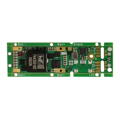
TCW Technologies Safety-Trim ST-1-12v-10a-BSTR User manual

Rev 1.1
1
Safety-TrimTM
Single Axis Servo Booster
Models:
ST-1-12v-10a-BSTR
ST-1-24v-10a-BSTR
Safety-Trim Single Axis Servo Booster is an electronic speed controller
designed specifically to operate DC electric servo motors up to 10 amps of rated
current.
The Safety-Trim Booster can receive input commands from compatible autopilot
systems such as the Garmin G3x GSA 28 or a traditional dpdt type rocker switch.
The servo booster receives trim commands from the autopilot system to enable
the auto-trim function and in turn drives servo trim motors requiring up to 10
amps of rated current. The servo booster may receive constant drive signals
from a traditional trim switch or PWM signals up to 25 kHz to allow for variable
rate trim functions
Safety-Trim is to be used with DC trim motors and linear actuators rated
for operation at up to 10 amps. 14 and 28 volt models are to be used with 14 and
28 volt actuators respectively. No other uses are permitted. Safety-Trim is not
TSO’d and must only be used in aircraft certified in the Experimental category.
Safety-Trim must be installed using the current aircraft standards and
practices. Refer to AC 43.13-2A/1B. The installer/builder is solely responsible
for determining the suitability of the installation and use of this product.

Rev 1.1
2
Installation instructions:
NOTE: ST-1-12v-10a-BSTR for 14 volt applications
ST-1-24v-10a-BSTR for 28 volt applications
1) Mount an on/off power switch or pull-able circuit breaker for the trim
controller in a suitable place in the aircraft and in reach of the pilot.
2) Connect the two RED #20 gauge wires coming from the connector to the
power switch to provide + Aircraft Power via a 10 amp fuse or circuit breaker.
Connect the two BLACK #20 gauge wires to –Aircraft ground. (as shown on
the wiring diagram)
3) Connect the trim input wires (green) to the corresponding wires as shown
in the wiring diagram. Connect these wires to the trim output terminals of the
autopilot servo. DO NOT connect an additional manual switches to these inputs
when utilizing an autopilot trim servo controller.
4) Pin #2 provides current limited power to a manual trim switch. This is an
optional connection. Alternate sources of manual trim switch power may be
provided through a separate CB or fuse.
5) Connect the trim motor to the Servo Booster outputs. Utilize one pair of
wires if the motor current is 5 amps or less. Utilize the redundant wire pairs if the
motor current is between 5-10 amps. It is highly recommended to connect the
power wire, ground wire and input wires first, then temporarily connect the
respective trim servo motor wires to verify the control surface moves in the
correct direction. The polarity of the trim servo motor wires will vary in different
aircraft and MUST be confirmed in your application.
YOU MUST ensure the trim surface moves in the proper direction as
activated by the trim switches. You may need to swap the elevator trim motor
wires A+, A- to get the elevator trim to go in the proper direction. ONLY after
verification of correct motion should you make permanent connections to the trim
servo motors.
DO NOT LET THE SERVO WIRES TOUCH EACH OTHER OR GROUND, this
will damage the Servo Booster!
6) Mount the Safety-Trim Control box inside the aircraft using the mounting
tabs on the enclosure.
7) ALL programing of the trim system is completed utilizing the instructions
provided by the Autopilot manufacturer. The Safety-trim Servo Booster follows
the commands issued by the autopilot auto-trim function, it does not have any
internal adjustments.

Rev 1.1
3
PRODUCT OPERATION
NORMAL Operation:
1) Place the power switch in the “ON” position.
2) Use the trim input switches to drive the respective trim servo in the
desired direction or utilize the auto-trim function per the instructions
provided by the autopilot manufacturer.
3) If any problem with the trim system is detected move the power switch
to the ‘OFF” position.
TCW Technologies, LLC. 610-928-3420
2955 Main Road East www.tcwtech.com
Emmaus, PA 18049

Rev 1.1
4
Power Switch or Pullable-CB
1
5
6
9
Aircraft ground
10 amp
Aircraft power
15
Pins 3,11 parallel connection
12 volt DC
servo actuator
Elevator trim servo
ON
OFF
Wiring Diagram Model ST-1-12v-10a-BSTR
7
NOTE: Parallel connections of
power, ground and servo wires
are for applications with servos
rated at more than 5 amps
Interconnection to Garmin G3x autopilot
Safety-Trim
Intelligent Servo Controller
Model ST-1-12v-10a-BSTR
Servo Booster
Input: 10-15 volt DC
Output: 0-15 volt,10 amps
Servo Booster Inputs
10 amps max.
Garmin Autopilot
Pitch Servo
GSA 28
Trim motor outputs
13
14
12
11
Center-off, momentary trim
switch, per Garmin manual
2manual trim switch power
Pins 4,12 parallel connection

Rev 1.1
5
Wiring Harness Connector Detail
NOTE:
USE redundant connections for the following pins when motor
load is greater than 5 amps
Power, ground, trim motor + and motor -
Pin #
Function
Wire color
1
Power +
Red
2
SWITCH POWER OUT
10mA limited
White/red
3
Trim motor +
Blue
4
Trim motor -
Yellow
5
Input from A/P
Green
6
Input from A/P
Green
7
Ground
Black
8
9
Power +
Red
10
11
Trim motor +
Blue
12
Trim motor -
Yellow
13
14
15
Ground
Black

Rev 1.1
6
TCW Technologies, LLC.
During the first 24 months from the date of purchase and subject to the conditions hereinafter set forth,
TCW Technologies, LLC. (TCW) will repair or replace to the original user or consumer any portion of
your new Safety-Trim product which proves defective due to defective materials or workmanship of TCW.
Contact TCW Technologies for warranty service. TCW shall have and possess the sole right and option to
determine whether to repair or replace defective equipment, parts or components. Damage due to
equipment, environment or conditions beyond the control of TCW Technologies are NOT COVERED BY
THIS WARRANTY.
LABOR, COSTS: TCW shall IN NO EVENT be responsible or liable for the cost of field labor or other
charges incurred by any customer in removing and/or reaffixing any TCW product, part or component
thereof.
THIS WARRANTY WILL NOT APPLY: (a) to defects or malfunctions resulting from failure to properly
install, operate or maintain the unit in accordance with printed instructions provided; (b) to failures
resulting from abuse, accident, or negligence; (c) to normal maintenance services and the parts used in
connection with such service; (d) to units which are not installed in accordance good trade practices; or (e)
to unit used for purposes other than for what it was designed and manufactured.
RETURN OR REPLACED COMPONENTS: any item to be replaced under this Warranty must be
returned to TCW Technologies in Emmaus, PA, or such place as TCW may designate, freight
prepaid.
PRODUCT IMPROVEMENTS: TCW reserves the right to change or improve its products or any
portions thereof without being obligated to provide such a change or improvement for units sold
and /or shipped prior to such change or improvement.
WARRANTY EXCLUSIONS: as to any specific TCW product, after the expiration of the time
period of the warranty applicable thereto as set forth above. THERE WILL BE NO
WARRANTIES, INCLUDING ANY IMPLIED WARRANTIES OR MERCHANTABILITY OR
FITNESS FOR ANY PARTICULAR PURPOSE.
Some states do not allow limitations on how long an implied warranty lasts, so the above
limitation may not apply to you. No warranties or representations at any time made by any
representative of TCW shall vary or expand the provisions hereof.
LIABILITY LIMITATION: IN NO EVENT SHALL TCW OR ITS AFFILIATES BE LIABLE OR
RESPONSIBLE FOR CONSEQUENTIAL, INCIDENTAL OR SPECIAL DAMAGES RESULTING
FROM OR RELATED IN ANY MANNER TO ANY TCW PRODUCT OR PARTS THEREOF. THE
SUITABILITY OF USE OF THE SAFETY-TRIM PRODUCT IS TO BE DETERMINED BY THE
AIRCRAFT HOMEBUILDER.
Some states do not allow the exclusion or limitation of incidental or consequential damages, so
the above limitation or exclusion may not apply to you.
This Warranty gives you specific legal rights and you may also have other rights which vary from
state to state. In the absence of other suitable proof of this installation date, the effective date of
this Warranty will be based upon the date of manufacture plus one year. Direct All Notices To:
Warranty and Product Service Department, TCW Technologies, 2955 Main Road East. Emmaus,
PA 18049
This manual suits for next models
1
Table of contents
Other TCW Technologies Controllers manuals
Popular Controllers manuals by other brands
Siemens
Siemens Synco 700 operating instructions

AMALGAMATED INSTRUMENT
AMALGAMATED INSTRUMENT PM5-TMR Operation and instruction manual

Gaspardo
Gaspardo GENIUS USE AND ASSEMBLY INSTRUCTIONS / SPARE PARTS

Mi-Light
Mi-Light MiBoxer FUT039SA user manual
iNels
iNels GSB3-40 manual
Honeywell
Honeywell RP920A Installation instructions manual
