TCW Technologies IPS-24v-5a User manual

1
Intelligent Power Stabilizer
& Up-converter
Model: IPS-24v-5a
The Intelligent Power Stabilizer, IPS, is an electronic power converter for critical
electrical equipment found in general aviation aircraft. The IPS system provides aircraft bus
voltage surge and sag protection for the connected electrical equipment. The IPS system
will operate over an input voltage range from 1 volts to 3 volts and provides a regulated
output voltage of 24 volts. The IPS system allows electronic equipment such as engine
monitors, EFIS and GPS’s and radios to be operational before and during engine starting.
This important feature allows the pilot to load flight plan data into the aircraft GPS prior to
starting the engine, thereby saving fuel and operating expense. When used with aircraft
engine monitors it ensures the pilot can monitor critical engine operating parameters such
as oil pressure during the engine starting process.
The electronic power converter in the IPS system ensures the connected electronic
equipment is provided with a stabilized source of power even when the aircraft battery
voltage drops significantly. This is particularly important during engine starting or alternator
out conditions. IPS additionally provides surge protection by actively clamping the
regulated output voltage.
The IPS-24V may also be used as an up converter for electronic equipment requiring
24 volts from a standard 12 volt aircraft power bus.
The Intelligent Power Stabilizer system is suitable for use with equipment such as
Garmin GNS-43 /wa, GNS-53 /wa, G9 X, G3X systems. Advanced Flight System EFIS,
Dynon EFIS, Grand Rapids EFIS, MGL EFIS, Tru-trak Autopilots. The IPS system may
also be used for operating 24 volt radios and electronics such as those utilized in the
Garmin G9 x system and the GNS 43 W-A / GNS-53 W-A systems in 12 volt aircraft.
No other uses of the IPS system are permitted except for those identified in this
installation manual.
IPS must be installed using the current aircraft standards and practices. Refer to
AC 43.13-2A/1B. The installer/builder is solely responsible for determining the suitability of
the installation and use of this product.

2
Installation instructions:
1. IMPORTANT NOTE:
Consult the attached wiring diagrams to identify wiring connections similar to your
particular installation. Please note, some equipment such as GPS’s and EFIS
systems may be provided with multiple power inputs. For these installations the IPS
system must be connected on the “back-up” power input. It is strongly
recommended that the “main” power input in these installations be provided from the
aircraft avionics bus. The “back-up” power source should be provided through the
IPS system and fed from a bus that is active during engine starting. This will
typically be the master bus. For equipment having a single source of power, ensure
the IPS system is fed from a bus that remains active during engine starting, such as
the master bus.
Garmin 43 /53 (w) GPS systems are available in versions with and without back-up
power inputs. Consult the Garmin GPS installation manual to determine which
model you are working with, wiring diagrams for connection of each type to the IPS
system are shown at the end of this document.
2. Check the total connected load to be used with the IPS system and ensure that it is
less than the following product ratings.
IPS-24v-5a = 5 amps maximum continuous current, 1 amps peak
3. Mount the IPS power converter in a suitable location in the aircraft. The IPS must be
mounted inside the aircraft, do not mount IPS in the firewall forward area.
4. Connect the aircraft wiring according to the wiring diagrams as shown.
The IPS must be powered through a properly sized circuit breaker or fuse. ENSURE
the proper size wire is utilized for the input feed and ground connection powering the
IPS system Additionally, the output of the IPS must be fused as shown in the wiring
diagrams.
FUSING:
For continuous loads: Input Fuse = 15 amps, Output Fuse= 5 amps
For radios and transient loads: Input Fuse = 2 amps, Output Fuse= 7.5 amps

4
SPECIFICATIO S:
Input Voltage: 10-30 volts DC
Output Voltage: >24.0 volts DC
Output Current: IPS-24v-5a 5 amps continuous, 10 amps peak
Converter:
True DC:DC converter with output over voltage,
over current and over temperature protection
Surge Protection: 32 volt active clamp, 1500w 10/1000uS waveform
Wiring: IPS-24v-5a : insulated barrier strip, #6 screws
Enclosure: Cast aluminum
IPS-24v-5a : 4.6” x 3.7” x 1.18”
Weight: IPS-24v-5a : 14 oz.
Temperature range: -25 C° to 55 C°

5
Intelligent Power Stabilizer
TM
12 volt Battery
Master Solenoid
15 amp
fuse
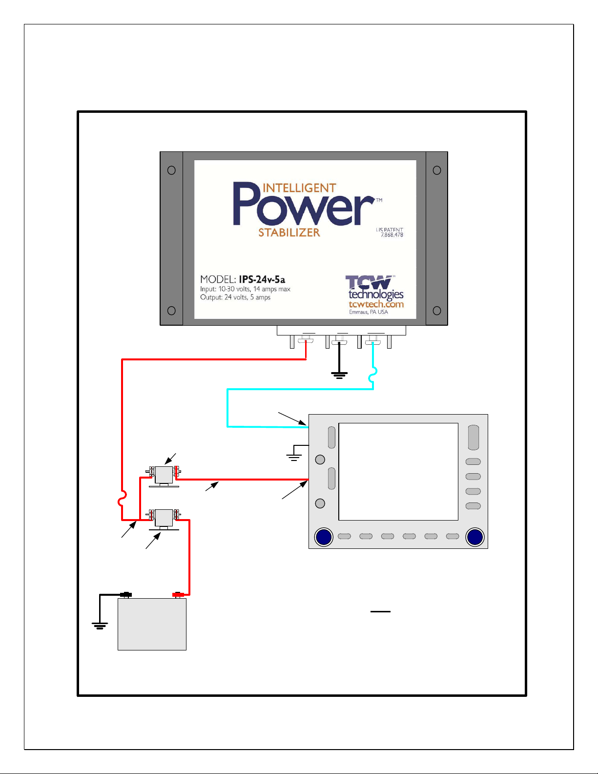
Wiring Diagram IPS-24v-5a
UP-CONVERTER MODE
24 Volt
Equipment being
powered via IPS
Example wiring for up-converting from 12 volt to 24 volts
Main Power Input
12 volt Main Bus
5- 7.5 amp output fuse
Grd V+OutV+in
6
Intelligent Power Stabilizer
TM
24 volt Battery
Master Solenoid
15 amp
fuse
Wiring Diagram IPS-24v-5a
Equipment
powered via IPS
Example wiring for systems with back-up power inputs
24 volt system utilizing IPS surge and sag protection
Back-up Power Input
Avionics Bus Solenoid
Avionics Bus
Main Power Input
Main Bus
Equip ent with Back-up Power Input
5 - 7.5 amp fuse
Grd V+OutV+in
Table of contents
Popular GPS manuals by other brands


Nextar
Nextar S3 user manual

Shenzhen v-sun Electronics
Shenzhen v-sun Electronics TLT-8A instruction manual

CanMore
CanMore CAN6-CT6 quick start guide
Classic tracker
Classic tracker OBD-II installation guide

Pioneer
Pioneer AVIC-Z150BH Operation manual

Pentagram
Pentagram PathFinder P 3106 Quick installation guide