TDE Instruments Digalox DPM72-MP+ User manual

Graphical panel meter for 500V/10A AC/DC with RGB multi display
! Panel meter Di alox® DPM72-MP+, mountin bracket,
5 jumpers, 2 instruction manuals (EN + DE)
" #$%
•Read instruction manual carefully before operatin the device! Keep for later
reference.
•Mountin and installation must be carried out by suitably qualified and competent
persons only.
•&'(()!*+,$+-%$+
.
•&+/ +-+0-1-
+ -. *+ 22 - $ +
"
•*+-1-+%,-,
+-/"
•The device is not intended to protect persons or facilities a ainst harm. Specific
devices must be used to uarantee safety (protection relays, cut-off switches,
etc.).
•When connectin switches to the terminals J1-J8, only switches must be used
whose isolation volta e is at least twice the maximum occurrin measurement
volta e. For example, when measurin 250;V AC switches must be isolated for at
least 500;V.
•Do not open the housin !
•Do not use the device in the presence of explosive or flammable substances!
•All cables carryin hazardous volta es must be secured with external separators.
" $%1
General warnin si n
(Attention, observe the documentation!)
Warnin of an electrical hazard
-----34-----

5" --
•Measurement of current, volta e, power and frequency in the specified measurin
ran es.
•Indoor use non condensin , non corrosive.
•Panel mountin .
•In operation, supply the device preferably via screw terminals with 12 to 24;V
AC/DC instead of via USB.
•Failure to comply with these instructions will void all uarantee and warranty.
" ,
The multi display with RGB backli ht is able to display up to four parameters
simultaneously. Thresholds can be associated with individual warnin backli ht
colours. A variety of measurement types (volt AC/DC, ampere AC/DC, frequency,
power, cos phi) are supported. The unit can be switched between display values via
an external switch. Minimum and maximum values of up to four parameters are
recorded and can be displayed optionally usin an external switch. Measured values
of one parameter are recorded over a time span of 36 seconds up to 14 days. The
time base as well as the display of the measurin history can be activated by an
external switch. The measured values remain stored as lon as the device is
supplied with volta e.
The followin parameters can be adjusted usin the confi uration software “Di alox®
Mana er”: scale endpoint, scale caption, display style (pointer, tachometer, bar
raph, and more), splash ima e, backli ht colour, thresholds for alarm output,
threshold warnin colour (li ht, blink), hysteresis, and more. Recorded
measurement values can be read and a continuous transmission of up to four
measurement values can be enabled. Usin the software, values can be viewed and
exported as CSV file. Dependin on the model, measured values can be transmitted
via USB, XBEE radio technolo y or RS485 Modbus interface. In addition, the
devices feature a countin function with data retention. This enables operatin -
hours-counters or time-counters for exceedin and fallin below threshold values, as
well as ampere-hour and ener y meters.
Visit ///"-" to download the software “Di alox® Mana er”.
-----34-----

6" -/
3
5
4
2
1
2
6
7
1 Unit or free text
2 Threshold values
3 Upper scale caption
4 Graphical measurement display
5 Di ital measurement value
6 Lower scale caption
Digalox DPM72-MP+
www.digalox.com
Made in Germany
USB
Output max.
30 V
50 mA
8
Supply
12 - 24 V
~/
Mode 1
Mode 2
Mode 3
Autocale
Min/Max
Timebae
Bu 1
Bu 2
NC
GPIO 1
GPIO 2
NC
J1
J2
J3
J4
J5
J6
J7
J8
J9
J12
J11
J10
Ilow Ihigh Uhigh Ulow
10 A max. 500 V max.
3
2
1
5
4
9
1 2 optocoupler switch outputs
2 Jumper pins J1–J12
for activatin /switchin of raphical
historic data display, min/max
display, auto-scalin , display value
(mode), ...
3 Supply volta e input
4 Interface
(USB Micro-B / XBEE / RS485)
5 Measurement inputs
:"
Carefully insert the device into the panel
cut-out. Insert the mountin bracket from
the back and push towards the panel until
the device sits ti ht. Make sure the
mountin bracket is snapped into the side
of the housin . To ensure IP65 protection
(dust and water jet) when mountin in a
front panel, use optional asket
(separately available).
-----534-----
Panel thickness: max. 6 mm
Press mountin
bracket

" ;
#,,%
<
12 - 24 V Fuse 250 mA
Supply
=-
max.
500 V
low high >high >low
+/L -/N
?-
low
high
Load
+/L -/N
max.
10 A
>
high
>
low
FF
10 A
?--
low
high
Load
+/L -/N
max.
10 A
max.
500 V
>
high
>
low
FF
10 A
?$
LoadCurrent
Transformer
low high >high >low
max.
10 A
FF
10 A
+/L -/N
?$@
-
LoadCurrent
Transformer
low high >high >low
max.
10 A
FF
10 A
+/L -/N
max.
500 V
?++-@
6=.
low
high
+/L -/N
max.
10 A max.
50 V!
>
high
>
low
FF
10 A
Load
?++-@
-@6=.
low
high
+/L -/N
max.
10 A max.
50 V!
>
high
>
low
FF
10 A
Load
&'(()!*+-%%1,-$+
,+/1.
'();!?+++-1/,-
-%$,6A=.++-
++,"%1--/+/+
2"
-----34-----

4" ?$
Connect the device to a computer:
>#9! Connect the device and the computer usin a USB cable. The
device driver is installed automatically if the computer is connected to
the Internet.
B9;;! Insert the XBEE stick into the computer. The device driver is
installed automatically if the computer is connected to the Internet. In
order to reset the XBEE settin s, short-circuit terminal J8.
#46! Short-circuit terminal J8. Disconnect the device from the
Modbus network and connect it to the computer usin an RS485 USB
adapter. After completin the confi uration, open J8 a ain.
Start the "Di alox® Mana er" software and connect it to the device. Settin s can
then be made on the various tabs and saved in the device.
Please note that the display value selected in “Di alox® Mana er” is displayed only
until the power supply of the DPM72 is interrupted.
$+,@+-/%+/+$-,%
++-1%+C,
22:1D-,%E@
$-,%%--%+$/-,%"
*1-,%$%,@1+-1%$/
-,% ,% -,%
1 V DC direct Volt DC
2 2
2 A DC direct Ampere DC
2 2
3 P DC direct Watt DC
2 2
4 V AC direct Volt AC
2 2
5 A AC direct Ampere AC
2 2
6 P AC direct Watt AC
2 2
7 AC Frequency Freq. AC
2 2
8 5A AC scaled
(current transformer)
Ampere CT
2 2
(! When usin a multi display style, AC and DC measurement cannot be done
simultaneously. The first display value used defines the type of measurement.
-----634-----

F" G+
The followin functions can be activated independently durin operation by short-
circuitin connectors J1-J3, e. . usin a jumper or switch:
2!),++--,%
The unit displays the stored values within
the set time base as a raphical trend. The
time base can be set to days (7, 14),
hours (1, 3, 6, 12, 24, 48, 72), minutes (3,
15, 30) or seconds (36).
The time base can be chan ed by
alternately openin and closin J1 (interval
< 2 sec). When first openin and closin J1
the current time base is displayed. For each
subsequent openin and closin the time
base chan es to the next settin . In order to
save the settin permanently, the software
“Di alox® Mana er” has to be used.
2!-,%
The display shows the maximum and
minimum values recorded since the last
reset. The values can be reset by openin
and closin connection J2 shortly (interval <
2 sec). The display shows “Minmax reset”.
25!'
The device automatically chan es the upper
scale caption dependin on the current
measurin value between 10, 100 and the
set upper scale caption.
-----:34-----

"
Periodically check all external cable connections.
" ?
Observe the safety instructions before cleanin the device. Clean the device with a
dry lint-free soft cloth. Do not use solvents.
" #,$
Supply 12 - 24 V AC/DC ±10% (50/60 Hz ±10%) or if
applicable via USB, alvanically isolated
Power consumption Max. 2.4 W
Display LCD raphic display 192 × 160 pixels,
16 rey levels with RGB backli ht
Measurin ran e volta e ±500 V AC/DC, 10 - 500 Hz
Accuracy volta e ±1 % true RMS
Internal resistance volta e 2.6 MΩ
Measurin ran e ampere ±10 A AC/DC and 5 A AC for current transformer,
10 - 500 Hz
Accuracy ampere ±1 % true RMS
Internal resistance ampere 5 mΩ
Measurin ran e frequency 10 - 1000 Hz
Accuracy frequency ±0.1 Hz
Measurin value update 5 Hz (32 kHz samplin rate)
Recordin of measurement 36 seconds to 14 days,
180 internal memory locations
Alarm outputs 2 optocoupler outputs max. 30 V DC, 50 mA
Connections
(measurin inputs)
- Wire au e
- Wire strip len th
- Pitch
0.2 - 3.3 mm² (24 to 12 AWG)
7 - 8 mm
7.62 mm
Connections (supply, alarm
outputs and RS485)
- Wire au e
- Wire strip len th
- Pitch
0.13 - 1.3 mm² (26 to 16 AWG)
6 - 7 mm
3.5 mm
Operatin temperature 0 °C to +50 °C
Stora e temperature -20 °C to +70 °C
Operatin altitude 0 to 2000 m above sea level
IP code IP65 (front), IP00 (back)
Dimensions 72 mm × 72 mm × 58 mm
Panel cut-out 68 mm × 68 mm
Depth 55.3 mm (with plu s, cable direction rear facin )
72.6 mm (with antenna)
Net wei ht 149
-----34-----

5" HI
" '1
TDE Instruments Di alox® DPM72 asket EPDM/SBR
6" ?$
TDE Instruments GmbH, Gewerbestraße 8, D-71144 Steinenbronn
Phone: +49 7157 20801
E-mail: [email protected]
Internet: www.tde-instruments.de, www.di alox.com
-----434-----
56.3
83.5
72.0
72.0
77.5
18.627.0
9.6
2.9
73.5
72.0
55.3
63.0
72.0
2.9
35.9
67.5
83.5
Panel cut-out
68.0
68.0
86.9
58.2
36.7
Table of contents
Other TDE Instruments TV Mount manuals
Popular TV Mount manuals by other brands
New Star
New Star PLASMA-W150 instruction manual
Tripp Lite
Tripp Lite DDR1327MQ owner's manual
C.P. Electronics
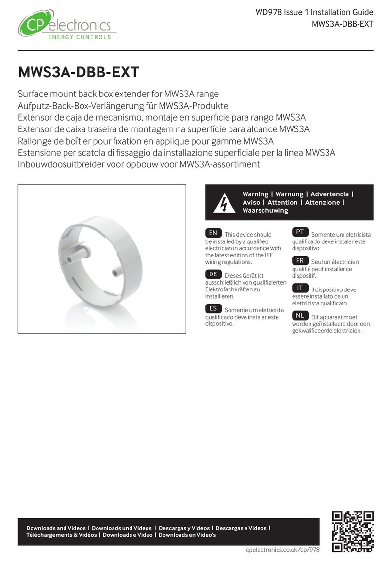
C.P. Electronics MWS3A-DBB-EXT installation guide
Rocket Fish
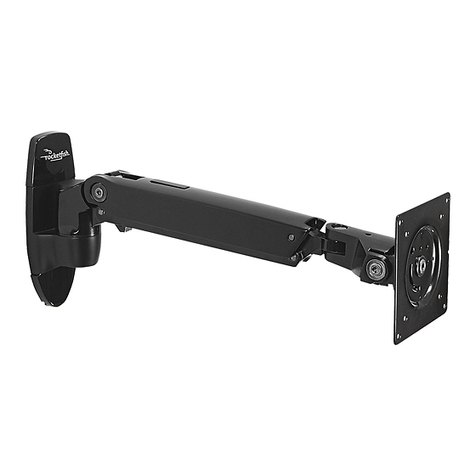
Rocket Fish RF-TVMP20 installation instructions
d & b audiotechnik
d & b audiotechnik Z Series Mounting instructions
d & b audiotechnik
d & b audiotechnik Z5038 Mounting instructions

