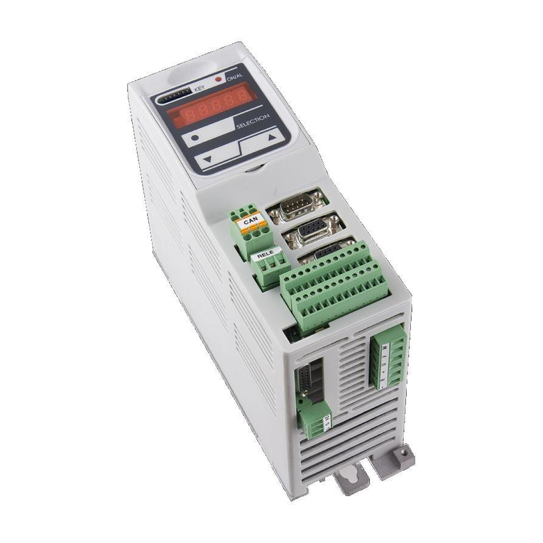
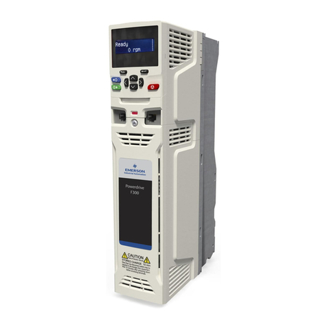
TDE MACNO OPDE User manual

Cod. MP00000B00 V_2.6
Products Tde Macno
Installation
OPDE


1
MP00000B00 V_2.6
Gentile cliente,
grazie per la fiducia accordataci nell’acquisto del nuo-
vo azionamento “OPDE”.
Ci auguriamo che il prodotto soddisfi pienamente le
Vostre aspettative attuali e future.
Il nostro personale tecnico è a vostra disposizione per
ogni ulteriore informazione.
Il presente manuale contiene le istruzioni necessarie
per l’installazione dell’apparecchiatura.
Per le altre informazioni relative al prodotto si rimanda
al “manuale utente” specifico per la tipologia di
azionamento
Dear Customer,
Thank you for the trust you have placed in us by
purchasing our new motor drive “OPDE”.
We hope that this product meets all your present and
future expectations.
Our technical staff is at your disposal for any further
information.
This instruction manual contains all the instructions
needed to install the equipment.
For any other information on this product please refer
to the “User Manual” pertaining to each specific type of
drive

2 MP00000B00 V_2.6
GARANZIA
1) Nei limiti di quanto stabilito nella presente garanzia,
il sottoscritto fabbricante si impegna a riparare tutti
gli eventuali difetti di costruzione che si manifestino
durante il periodo di garanzia, fissato in 12 (dodici)
mesi dalla data di vendita .
2) La garanzia decade qualora l’acquirente non
esegua correttamente le previste norme descritte
nelle presenti “Istruzioni per l’installazione”.
3) Al fine di potersi avvalere del diritto di garanzia, l’ac-
quirente, al manifestarsi del difetto, dovrà darne
tempestivamente comunicazione al fabbricante e
permettere, se ritenuto necessario, di effettuare le
relative ispezioni e riparazioni.
4) Sono a carico dell’acquirente le spese di trasporto
per l’invio al fabbricante e la relativa restituzione del
pezzo difettoso, coperto da garanzia, per la
riparazione o la sostituzione del medesimo.
L’obbligo di garanzia, come previsto nella presente
clausola, si considera adempiuto con la consegna
all’acquirente del pezzo adeguatamente riparato o
sostituito.
5) Nel periodo di garanzia di cui alla clausola 1) i costi
di manodopera, per la riparazione, saranno a carico
del fabbricante.
Nel caso in cui le riparazioni o le sostituzioni debba-
no essere effettuate dal cliente, le spese di viaggio e
di soggiorno del personale saranno a carico dell’ac-
quirente.
6) Restano escluse dalla garanzia le rotture provocate
da manovra errata, imperizia, caso fortuito o
comunque imputabile all’utente, sia per fatto e
causa propria che di terzi oppure quando l’acquiren-
te abbia apportato modifiche od effettuato riparazio-
ni senza il consenso scritto del fabbricante, indipen-
dentemente dalla connessione tra tali modi-
fiche o riparazioni ed i difetti rilevati.
7) Viene espressamente pattuito che il fabbricante
sarà esonerato da qualsiasi responsabilità
conseguente ad eventuali danni derivanti all’acqui-
rente da mancata o diminuita produzione, conse-
guenti a vizi o difetti di costruzione per i quali sarà
operante la presente garanzia.
WARRANTY
1) Within the limits of this Warranty, the undersigned
Manufacturer undertakes to repair any defects in
workmanship that may be detected during the
warranty period which is 12 (twelve) months from
the date of sale.
2) This Warranty shall be void if the Buyer does not
follow all the instructions described in these
“Installation Instructions”.
3) In order to avail itself of its rights under the Warran-
ty, Buyer must immediately notify the Manufacturer
of any defects and allow the Manufacturer to inspect
and remedy defects, if deemed necessary.
4) Buyer shall bear all transportation costs of shipment
of the defective part, covered by the provisions of
this Warranty, to the Manufacturer for repair or
replacement, as well as the costs of return of such
part.
By delivering a duly repaired or replaced part to the
Buyer, the Manufacturer shall be deemed to have
fulfilled its warranty obligation under this clause.
5) Within the warranty period referred to in clause 1)
the Manufacturer shall bear all labor costs for the
repair of the defective part.
If repairs or replacements are to be carried out at
the Customer’s premises, all travel and living
expenses for the Manufacturer’s personnel shall be
borne by the Buyer.
6) Breakdowns or failures due to misuse, unskilfulness
or fortuitous event or to an event for which the User
is responsible in any way whatsoever, whether
through its own fault or through the fault of third
parties, or due to alterations or repairs made by the
Buyer without the prior written permission of the
Manufacturer, regardless of whether there is a con-
nection between such alterations or repairs and the
defects detected, are not covered by this
Warranty.
7) It is expressly agreed that the Manufacturer shall in
no event be liable for damages suffered by the
Buyer as a consequence of loss of or reduced pro-
duction, resulting from defects in workmanship co-
vered by this Warranty.

3
MP00000B00 V_2.6
INTRODUCTION........................................
Warranty .................................................................
TABLE OF CONTENTS........................
1- CE MARKING
1.1- CE Marking / Data plate .............................
2- GENERAL INFORMATION
2.1- Importance of this Manual..........................
2.2- Consultation Notes.....................................
2.2.1- Addressees of this Manual
(Authorized Operators).................
2.2.2- “Device Off” Status...........................
2.3- Abbreviations .............................................
2.4- All Rights Reserved....................................
3- TECHNICAL DESCRIPTION
3.1- Name of the Device....................................
3.2.- OPDE Code ..............................................
3.3- OPDE code for energy power applica-
tions…………………………………………….
3.4- Component Names and Sizes………………
………………………………………………………
3.5- Technical Data ...........................................
3.6- Intended Use .............................................
3.7- Operational Steps ......................................
3.8- Use Limitations ..........................................
4- TRANSPORTATION AND
HANDLING
4.1- Transportation............................................
4.2- Packaging ..................................................
4.3- Handling and Lifting the Package...............
4.4- Unpacking ..................................................
4.5- Storage ......................................................
4.5.1- Environmental storage conditions ....
4.5.2- Recovery procedure after storage....
5- INSTALLATION
5.1- Installation..................................................
5.1.1- Optional boars installation…………..
5.2- Electrical Connections................................
5.2.1- Power Stage.....................................
5.2.2- Mains Connection ............................
5.2.2.1 - Using differential switches
(ELCB) / Residue current devices
(RDC) ...........................................
5.2.3- Pre-charge (Soft Start) .....................
5.2.4- Connecting the Motor.......................
5.2.5- Grounding the Drive .........................
5.2.6- Braking.............................................
INDICE / INDEX
PRESENTAZIONE....................................
Garanzia..................................................................
INDICE...............................................................
1- MARCATURA CE
1.1- Marcatura CE / Targa dati............................
2- GENERALITÀ
2.1- Importanza del manuale...............................
2.2- Note di consultazione...................................
2.2.1- Destinatari (operatori autorizzati) .......
2.2.2- Stato “apparecchio spento” ................
2.3- Abbreviazioni................................................
2.4- Diritti riservati ...............................................
3- DESCRIZIONE TECNICA
3.1- Denominazione dell’apparecchio .................
3.2- Codifica OPDE .............................................
3.3- Codifica OPDE per applicazioni energie
alternative..................................................................
3.4- Denominazione dei componenti e
dimensioni ....................................................
3.5- Dati tecnici....................................................
3.6- Destinazione d’uso ......................................
3.7- Fasi di utilizzo...............................................
3.8- Limiti d’uso ...................................................
4- TRASPORTO E
MOVIMENTAZIONE
4.1- Trasporto dell’azionamento..........................
4.2- Imballo .........................................................
4.3- Sollevamento e movimentazione dell’imballo
4.4- Sballaggio ....................................................
4.5- Magazzinaggio.............................................
4.5.1- Condizioni ambientali di
magazzinaggio ...................................
4.5.2- Procedura di recupero dopo il
magazzinaggio ...................................
5- INSTALLAZIONE
5.1- Installazione .................................................
5.1.1– Installazione schede opzionali ..……
5.2- Collegamenti elettrici....................................
5.2.1- Sessione di potenza...........................
5.2.2- Collegamento alla rete .......................
5.2.2.1 - Utilizzo di interruttori differenziali
(ELCB) / del dispositivo di corrente
residua (RDC) ..............................
5.2.3- Precarica............................................
5.2.4- Collegamento del motore ...................
5.2.5- Collegamento a terra dell’azionamento
...........................................................
5.2.6- Frenatura............................................
pag. 5
pag. 1
pag. 2
pag. 3
pag. 6
pag. 7
pag. 7
pag. 8
pag. 9
pag. 9
pag. 10
pag. 10
pag. 11
pag. 13
pag. 24
pag. 28
pag. 29
pag. 29
pag. 30
pag. 30
pag. 30
pag. 30
pag. 30
pag. 31
pag. 31
pag. 32
pag. 34
pag. 37
pag. 39
pag. 40
pag. 41
pag. 41
pag. 42
pag. 43
pag. 44

4 MP00000B00 V_2.6
INDICE / INDEX
5.2.7 - Connettore X3………………………….
5.2.8- Connessione con BUS in comune.....
5.2.9- Disposizioni connessioni di potenza
(rete, motore).....................................
5.2.10- Collegamenti logici ..........................
5.2.11- Collegamenti logici digitali e
analogici...........................................
5.2.12- Ingresso infrequenza .......................
5.2.13- Collegamenti I/O digitali e analogici.
5.2.14- Alimentazioni ...................................
5.2.15- Gestione sensore termico motore ed
encoder simulato..............................
5.2.16- Collegamenti Safe Torque Off
(S.T.O) (opzionale)............................
5.2.17- Collegamenti sincronismi A.F.E/
STARTER (opzionale).......................
5.2.18- Collegamenti uscita relè di fine pre-
carica A.F.E (opzionale)....................
5.2.19- Collegamenti alimentazione ventole
di raffreddamento (opzionale)............
5.2.20- Configurazione di default I/O ...........
5.2.21- Gestione scelta ingressi analogici
5.3 - Collegamento schede opzionali ................
5.3.1- TTL Encoder......................................
5.3.2- Resolver ............................................
5.3.3- Encoder e sensore di Hall ................
5.3.4- Sin cos encoder incrementale ..........
5.3.5- Sin cos Encoder assoluto ..................
5.3.6- ENDAT 2.1 .......................................
5.3.7- ENDAT 2.2 / BISS
5.3.8- Resolver alta risoluzione (RDC)........
5.3.9- Hiperface
5.3.10-Ingresso analogico ad alta risoluzione
5.3.11- Active Front End (A.F.E.)…………...
5.3.12- CAN BUS ........................................
5.3.13- PROFIBUS…………………………..
5.3.14- ETHERCAT………………………….
5.3.15- ANYBUS……………………………..
5.4- Collegamento linea seriale RS422/485......
5.5- Ingresso linea ............................................
5.6- Frenatura ...................................................
5.7- Opzioni lato motore....................................
5.8- Capacità all’interno del drive OPDE...........
6- SICUREZZA
6.1- Direttive e norme di riferimento ..................
6.2- Scelta di fusibili, induttanza di ingresso,
resistenze di frenatura................................
6.3- Accorgimenti antidisturbo...........................
6.4- Collegamento/ fissaggio delle schermature
per OPDE....................................................
pag. 44
pag. 45
pag. 46
pag. 52
pag. 54
pag. 55
pag. 56
pag. 57
pag. 57
pag. 58
pag. 59
pag. 59
pag. 59
pag. 61
pag. 62
pag. 63
pag. 63
pag. 64
pag. 65
pag. 66
pag. 66
pag. 67
pag. 67
pag. 68
pag. 69
pag. 70
pag. 70
pag. 71
pag. 72
pag. 73
pag. 74
pag. 75
pag. 76
pag. 78
pag. 79
pag. 80
pag. 81
pag. 82
pag. 83
pag. 85
5.2.7 - X3 connector…………………………
5.2.8- Connection via Shared BUS.............
5.2.9- Power Connections Layout
(Mains, Motor) ..................................
5.2.10- Logic Connections..........................
5.2.11- Digital and Analog Logic
Connections.................................
5.2.12- Frequency Input .............................
5.2.13- Digital and Analog I/O connections
5.2.14- Power Supply .................................
5.2.15- Management of Motor Thermal
Sensor and simulated encoder ......
5.2.16- Safe Torque off connections (S.T.O)
(option)………………………………..
5.2.17- A.F.E./STARTER synchronisms con-
nections (option)……………………..
5.2.18- End A.F.E. soft-start relay output
connections (option)…………………
5.2.19- Cooling fans power supply connec-
tions (option)………………………….
5.2.20- Default I/O Configuration ................
5.2.21- Management choice of analog inputs
5.3 - Optional boards connection......................
5.3.1- TTL Encoder.....................................
5.3.2- Resolver ...........................................
5.3.3- Encoder and Hall sensor .................
5.3.4- Incremental sin cos encoder ............
5.3.5- Absolute sin cos encoder ................
5.3.6- ENDAT 2.1 .......................................
5.3.7- ENDAT 2.2 / BISS
5.3.8- High resolution resolver (RDC)……..
5.3.9- Hiperface
5.3.10- High resolution analog input………...
5.3.11- Active Front End (A.F.E.)…………..
5.3.12- CAN BUS .......................................
5.3.13- PROFIBUS…………………………..
5.3.14- ETHERCAT…………………………..
5.3.15- ANYBUS……………………………..
5.4- RS422/485 Serial Connection...................
5.5- Line Input ..................................................
5.6- Braking......................................................
5.7- Options – Motor Side ................................
5.8- Capacity in the OPDE drive………………..
6- SAFETY
6.1- Reference Directives and Standards ........
6.2- Selecting Fuses, Input Choke & Braking
Resistor ......................................................
6.3- Interference Suppression Measures .........
6.4- Connection/Fixing of shields on
OPDE.......................................................

5
MP00000B00 V_2.6
FIG. 1 (Marcatura CE e targa dati / CE Marking and data plate)
1.1- MARCATURA CE / TARGA
DATI
La marcatura CE attesta la conformità dell’apparecchio
ai requisiti essenziali di sicurezza e di salute previsti
dalle Direttive europee riportate nella dichiarazione CE
di conformità.
È costituita da una etichetta adesiva in poliestere colo-
re argento con stampa di colore nero, delle seguenti
dimensioni: L= 102 mm - H= 50 mm (FIG. 1).
È applicata esternamente su un lato o sul pannello
anteriore. Nella targhetta sono indicati in modo leggibi-
le ed indelebile i seguenti dati (alcuni di questi dati
possono essere volutamente mancanti o riportati
parzialmente):
Il logo
La marcatura CE che attesta la conformità dell’ap-
parecchio ai requisiti essenziali di sicurezza e di sa-
lute previsti dalle Direttive europee
Il tipo
Il numero di serie
Il numero d’ordine
Software
La data di collaudo
Tensione di alimentazione elettrica
La corrente nominale
La corrente di picco
————————————————————————
Adattato per il tipo di motore
La corrente nominale del motore
Il picco di corrente del motore
La velocità del motore
Le opzioni del motore
1.1- CE MARKING / DATA PLATE
The CE marking attests that the equipment complies
with the essential safety and health requirements
provided for in the European Directives referred to in
the CE Declaration of Conformity.
The CE marking consists of a silver-colored polyester
adhesive label, printed in black, with the following
dimensions: L= 102 mm - H= 50 mm (FIG. 1).
The label is fixed on a side of each device or on the
front panel. The following information is written legibly
and indelibly on the data plate (some data may be
omitted or partially indicated):
• Logo
• CE marking attesting that the device complies with
the essential safety and health requirements of the
European Directives
• Type
• Serial nr.
• Order number
• Software
• Testing Date
• Nominal input Voltage
• Nominal Current
• Peak Current
————————————————————————
• Adjust for Motor Type
• Motor nominal Current
• Motor peak Current
• Motor speed
• Motor options

6 MP00000B00 V_2.6
2.1- IMPORTANZA DEL MANUALE
Il presente manuale tecnico per l’installazione è stato
redatto al fine di garantire una facile e corretta compren-
sione degli argomenti trattati, da parte degli operatori
autorizzati all’utilizzo e alla manutenzione dell’apparec-
chio in oggetto.
Se, nonostante l’attenzione prestata in fase di redazione
da parte del fabbricante, gli operatori suddetti
riscontrassero qualche incomprensione nella lettura, so-
no pregati, onde evitare errate interpretazioni personali
che compromettano la sicurezza, di richiedere tempesti-
vamente al fabbricante le corrette spiegazioni ed ulterio-
ri informazioni.
Prima di utilizzare l’apparecchio in oggetto, gli operatori
autorizzati devono obbligatoriamente leggere e com-
prendere in tutte le sue parti il presente manuale tecnico
di “Istruzioni per l’installazione” e attenersi rigorosamen-
te alle norme ivi descritte, al fine di garantire la propria e
l’altrui sicurezza, ottenere le migliori prestazioni dell’ap-
parecchio e assicurare a tutti i suoi componenti la mas-
sima efficienza e durata.
Il presente manuale deve, in qualsiasi momento, essere
a disposizione degli operatori autorizzati e trovarsi, ben
custodito e conservato, sempre vicino all’apparecchio.
IL FABBRICANTE DECLINA OGNI RESPONSABILITÀ
PER DANNI A PERSONE, ANIMALI E COSE CAUSATI
DALL’INOSSERVANZA DELLE NORME E DELLE AV-
VERTENZE DESCRITTE NEL PRESENTE MANUALE.
IL PRESENTE MANUALE DEVE ESSERE OBBLIGATO-
RIAMENTE CONSEGNATO ASSIEME ALL’APPAREC-
CHIO QUALORA VENGA CEDUTO AD ALTRO UTILIZ-
ZATORE.
IL PRESENTE MANUALE RISPECCHIA LO STATO
DELLA TECNICA AL MOMENTO DELLA COMMERCIA-
LIZZAZIONE DELL’APPARECCHIO E NON PUÒ ESSERE
CONSIDERATO INADEGUATO SOLO PERCHÉ IN BASE
A NUOVE ESPERIENZE PUÒ ESSERE SUCCESSIVA-
MENTE AGGIORNATO.
IL PRESENTE MANUALE DEVE SEMPRE ESSERE A
DISPOSIZIONE DEGLI OPERATORI AUTORIZZATI E
TROVARSI NELLE VICINANZE DELL’APPARECCHIO
BEN CUSTODITO E CONSERVATO.
2.1- IMPORTANCE OF THIS
MANUAL
PRIOR TO USING THE DEVICE HEREIN, AUTHORIZED
OPERATORS MUST THOROUGHLY READ AND UNDER-
STAND THIS ENTIRE MANUAL.
This installation technical manual has been drawn up to
ensure that the subjects dealt with in it are easily and
correctly understood by the operators authorized to use
the device referred to herein and to carry out the rele-
vant maintenance.
If, despite the care taken by the manufacturer in drawing
up this manual, the above operators have any difficulties
in understanding its contents, they should immediately
ask for proper explanations and additional information
from the manufacturer, to avoid wrong personal
interpretations that might jeopardize safety.
Before using the device referred to herein, authorized
operators must thoroughly read and understand this
technical manual on “Installation Instructions” and stric-
tly follow all the instructions and norms contained he-
rein, so as to guarantee their own personal safety as
well as that of others and obtain the best possible
performance from the drive, while ensuring top
efficiency and a long service life of all of its
components. This manual must be readily available to
all authorized operators and must always be kept in
good condition near the device.
THE MANUFACTURER HEREBY DISCLAIMS ALL
LIABILITY FOR INJURIES OR DAMAGE THAT COULD
BE CAUSED TO PERSONS, ANIMALS OR PROPER-
TY DUE TO FAILURE TO FOLLOW THE INSTRUCTIONS
AND WARNINGS IN THIS MANUAL.
THIS MANUAL MUST BE GIVEN TO THE END USER
TOGETHER WITH THE DEVICE, SHOULD THE DEVICE
BE RESOLD OR TRANSFERRED TO ANOTHER USER.
THIS MANUAL REFLECTS THE STATE-OF-THE-ART
TECHNOLOGY AT THE TIME OF SALE OF THE DEVICE
AND CANNOT BE CONSIDERED INADEQUATE JUST
BECAUSE UPDATED AT A LATER TIME, BASED ON
NEW EXPERIENCE.
THIS MANUAL MUST BE AVAILABLE TO AUTHORIZED
OPERATORS AT ALL TIMES AND MUST BE KEPT IN
GOOD CONDITION NEAR THE DEVICE.
PRIMA DI UTILIZZARE L’APPARECCHIO IN OGGETTO È
OBBLIGATORIO CHE GLI OPERATORI AUTORIZZATI
LEGGANO E COMPRENDANO IN TUTTE LE SUE PARTI
IL PRESENTE MANUALE.

7
MP00000B00 V_2.6
OPERATORE ADDETTO
(COLLAUDATORE)
È un tecnico qualificato (persona idonea in possesso
dei requisiti tecnico-professionali richiesti dalle norma-
tive vigenti), abilitato ad eseguire l’installazione e l’uti-
lizzo dell’apparecchio operando anche in presenza di
tensione elettrica e con le protezioni disabilitate (su
consenso del responsabile della sicurezza) nel rispet-
to assoluto delle istruzioni riportate nel presente ma-
N.B. (Nota Bene): testo maiuscolo riquadrato.
Grassetto: Evidenzia nel testo alcune frasi significati-
ve.
Inclinato: Descrive le didascalie delle figure e delle
tabelle.
Avvertenza scariche: indica la presen-
za di scariche elettrostatiche che po-
trebbero danneggiare l’apparecchiatu-
ra.
2.2.1- DESTINATARI
(OPERATORI AUTORIZZATI)
.
Questo manuale tecnico è destinato esclusivamente
agli operatori autorizzati, all’uso e alla manutenzione
dell’apparecchio in base alle specifiche competenze
tecnico professionali richieste per il tipo di intervento.
I simboli di seguito indicati sono disposti all’inizio di un
capitolo e/o di un paragrafo ad indicare quale sia l’o-
peratore interessato all’argomento trattato.
GLI OPERATORI AUTORIZZATI DEVONO ESEGUIRE
SULL’APPARECCHIO ESCLUSIVAMENTE GLI INTER-
VENTI DI LORO SPECIFICA COMPETENZA.
GLI OPERATORI AUTORIZZATI, PRIMA DI ESEGUIRE
QUALSIASI INTERVENTO SULL’APPARECCHIO, DEVO-
NO ASSICURARSI DI ESSERE IN POSSESSO DELLE
PIENE FACOLTÀ PSICO-FISICHE TALI DA GARANTIE
SEMPRE IL RISPETTO DELLE CONDIZIONI DI SICU-
REZZA.
2.2- NOTE DI CONSULTAZIONE
IL SEGNALE DI PERICOLO GENERICO E IL TESTO IN
MAIUSCOLO RIQUADRATO, RICHIAMANO L’ATTEN-
ZIONE DELL’OPERATORE SULLE AVVERTENZE RI-
PORTATE NEL PRESENTE MANUALE.
2.2- CONSULTATION NOTES
THE GENERAL DANGER SIGN AND THE TEXT IN
BLOCK CAPITALS INSIDE A BOX DRAW THE OPERA-
TOR’S ATTENTION TO THE WARNINGS CONTAI-
NED IN THIS MANUAL.
OPERATOR IN-CHARGE (TESTER)
Qualified technician (suitable person possessing the
technical and vocational skills required by the
regulations in force) who is entitled to install and use
the device, including in the presence of electrical
current and with the protections disabled (with the prior
permission of the person in charge of safety) in com-
pliance with the instructions contained in this
manual or in any other special document provided by
N.B. (Nota Bene): Text in block capitals within boxes.
Bold type: Highlights important phrases in the text.
Italics: Used for captions of figures and tables.
Warning discharge: It indicates the
presence of electrostatic discharge
which can damage the equipment.
2.2.1- ADDRESSEES OF THIS
MANUAL (AUTHORIZED
OPERATORS).
This technical manual is addressed solely to operators
authorized to use the device and carry out its
maintenance, according to the specific technical and
professional skills required for each type of task.
The symbols shown below appear at the beginning of
each section and/or paragraph, in order to indicate the
type of operator concerned with the subject dealt with
therein.
AUTHORIZED OPERATORS MAY ONLY CARRY OUT
TASKS WITHIN THEIR OWN SPECIFIC COMPETENCE.
PRIOR TO PERFORMING ANY WORK ON THE DEVICE,
AUTHORIZED OPERATORS MUST ENSURE THAT
THEIR OWN PSYCHOLOGICAL AND PHYSICAL CONDI-
TIONS ARE SUCH AS TO ENSURE OBSERVANCE OF
SAFETY PROCEDURES AT ALL TIMES.
IN CASO DI SMARRIMENTO O DETERIORAMENTO DEL
MANUALE RICHIEDERNE COPIA AL FABBRICANTE
SPECIFICANDO I DATI DI IDENTIFICAZIONE DELL’AP-
PARECCHIO (V. MARCATURA CE / TARGA DATI) E LA
REVISIONE.
IF THE MANUAL IS LOST OR DAMAGED, REQUEST A
COPY FROM THE MANUFACTURER, QUOTING THE
DEVICE IDENTIFICATION DATA (CE MARKING / DATA
PLATE) AND REVISION.

8 MP00000B00 V_2.6
nuale o altro documento specifico fornito esclusiva-
mente dal fabbricante.
OPERATORE AUTORIZZATO
ALLA MOVIMENTAZIONE
È un operatore professionalmente addestrato, che
abbia compiuto il 18° anno di età, nel rispetto della
legislazione vigente nel paese di utilizzazione.
RESPONSABILE DELLA SICUREZ-
ZA AZIENDALE
È un tecnico qualificato designato dal Cliente in
possesso dei requisiti tecnico professionali richiesti
dalle normative vigenti in materia di sicurezza e di
salute dei lavoratori sui luoghi di lavoro.
TECNICO DEL FABBRICANTE
È un tecnico qualificato messo a disposizione dal
fabbricante e/o dal rivenditore autorizzato per effettua-
re l’assistenza tecnica richiesta, interventi di manuten-
zione ordinaria e straordinaria e/o operazioni non
riportate nel presente manuale che richiedano una
conoscenza specifica dell’apparecchio.
2.2.2- STATO “APPARECCHIO
SPENTO”
Prima di eseguire qualsiasi tipo di intervento manuten-
tivo e/o regolazione sull’apparecchio è obbligatorio
sezionare la fonte di alimentazione elettrica.
L'azionamento è da ritenersi spento se è verificata
almeno una delle seguenti condizioni:
• Vengono tolti i fusibili in serie alla rete di alimentazio-
ne
• disinnescando l'interruttore principale su tutti i poli
• non fornendo alcuna alimentazione
Inoltre deve essere aspettato un tempo minimo di 8
min per assicurarsi che tutte le parti in tensione siano
scariche come indicato nelle etichette adesive applica-
te all’azionamento OPDE (v. FIG. 2).
the manufacturer only.
OPERATOR AUTHORIZED TO
HANDLE THE DEVICE
Trained, skilled operator, aged 18 and up, complying
with the laws in force in the country of use.
COMPANY SAFETY MANAGER
Qualified technician designated by the Customer,
possessing the technical and vocational skills required
by the regulations in force on health and safety at the
work place.
MANUFACTURER’S TECHNICIAN
Qualified technician provided by the manufacturer and/
or by an authorized dealer, in order to carry out the
requested technical assistance, routine and special
maintenance tasks, or any tasks not indicated in this
manual, which require in-depth knowledge of the
device.
2.2.2- “DEVICE OFF” STATUS
Always disconnect the device from the power source
before performing any maintenance or adjustment.
The drive shall be deemed to be off when at least one
of the following conditions is met:
• the fuses connected in series with the power supply
have been removed
• the main switch is disconnected at all poles
• no power is supplied
In addition to the above, allow at least 8 minutes in
order to make sure that all power inside live
components is fully discharged, as indicated on the
adhesive label affixed to the OPDE (s. FIG. 2).
LA MOVIMENTAZIONE MANUALE DELL’APPAREC-
CHIO DEVE AVVENIRE NEL RISPETTO DELLE NORMA-
TIVE SULLA “MOVIMENTAZIONE MANUALE DEI CARI-
CHI” ONDE EVITARE CONDIZIONI ERGONOMICHE
SFAVOREVOLI CHE COMPORTINO RISCHI DI LESIONI
DORSO-LOMBARI.
MANUAL HANDLING OF THE DEVICE MUST BE
CARRIED OUT IN COMPLIANCE WITH THE
REGULATIONS ON “MANUAL HANDLING OF LOADS”
IN ORDER TO AVOID UNFAVOURABLE ERGONOMIC
CONDITIONS THAT INVOLVE RISKS OF BACK OR
LUMBAR INJURY.

9
MP00000B00 V_2.6
2.4- DIRITTI RISERVATI
I diritti riservati riguardanti questo manuale “Istruzioni
per l’installazione” rimangono in possesso del
Fabbricante.
Ogni informazione (testo, disegni, schemi, ecc...) qui
riportata è riservata. Nessuna parte del presente
manuale può essere riprodotta e diffusa
(completamente o parzialmente) con un qualsiasi
mezzo di riproduzione, (fotocopie, microfilm o altro)
senza l’autorizzazione scritta da parte del Fabbricante.
Tutti i marchi citati appartengono ai rispettivi pro-
prietari.
2.3- ABBREVIAZIONI
Nella TAB. 1 sono elencate alcune abbreviazioni
usate nel manuale.
TAB. 1 (Abbreviazioni / Abbreviations)
ca. / ca. Circa / Approx. Min / min Minuti / Minutes
cap. / Sec. Capitolo / Section N. / N. Numero / Number
DPI / PPE Dispositivi di Protezione Individuale
Personal Protective Equipment pag. / pag. Pagina / Page
DX / RH Destro/a / Right-Hand par. / par. Paragrafo / Paragraph
h / h Ore / Hours Pos. / Pos. Posizione / Position
EN / EN European Norm / European Norm (Standard) RIF. / REF. Riferimento / Reference
Es. / Ex. Esempio / Example s / s Secondi / Seconds
FIG. / FIG. Figura/e / Figure-Figures SX / SX Sinistro/a / Left-Hand
max. / max. Massimo/a / Maximum TAB. / TAB. Tabella / Table
min. / min. Minimo/a / Minimum v. / s. Vedi / See
2.4- ALL RIGHTS RESERVED
All rights on this “Installation Instructions” manual shall
remain the property of the Manufacturer.
All information contained herein (texts, drawings,
diagrams, etcetera) is reserved. No part of this manual
may be reproduced or disseminated (whether in full or
in part) by any reproduction means (including photoco-
pying, microfilming etc.) without the prior written per-
mission of the Manufacturer.
All trademarks referenced herein are the property of
their respective owners.
FIG. 2 (Etichetta segnaletica / Warning label)
2.3- ABBREVIATIONS
Some of the abbreviations appearing this manual are
listed in TAB. 1.

10 MP00000B00 V_2.6
3.1- DENOMINAZIONE DELL’APPA-
RECCHIO
L’apparecchio in oggetto è così denominato:
Azionamento OPDE
3.1- NAME OF THE DEVICE
The device referred to here in is called:
5
V
0
Livello / Level 5= livello 5/ 5 level
OPDE D1= OPDE
Tipo / Type A= A.F.E. (Active Front End)
B= Brushless / Brushless sensorless
C= Chopper
M= Inverter con sincronizzante (Starter)
V= Field oriented control + Vector V/f
Taglia / Size (1)
003= 3A (1,5 kW) - 007= 7A (3 kW) - 012= 12A (5,5 kW) - 015= 15A (7,5 kW) - 022= 22A (11 kW)
032= 32A (15 kW) - A40= 40A (20 kW) - A48= 48A (22 kW) - A60= 60A (30 kW) - 070= 70A (37 kW)
090= 90A (45 kW) - 110= 110A (55 kW) - 150= 150A (75 kW) - 175= 175A (90 kW) - 220= 220A (110 kW)
250= 250A (132 kW) - 310= 310A (160 kW) - 370= 370A (200 kW) - 460= 460A (250 kW) - 570= 570A (315kW)
Sovraccarico / Over-
load X= Standard (5 kHz PWM) (Tutti i sovraccarichi possibili / All overload)
A= 8 kHz PWM - B= 4 kHz PWM - C= 3 kHz PWM - D= 2 kHz PWM
Tensione rete / Main
supply 3T= 380V trifase / 3 phase 3D= 310V VDC
5D= 560V VDC
Drive
A= Drive+Reg.—>24V ext. (case S-M-L-X) - B= Drive+Reg. —>24V ext.+STO (case S-M-L-XL)
C= Drive+Reg.—> Autofeed 24V int (case S-M-L-X) - H = Drive+Reg.—>24V ext (case 1) - F= Drive+Reg.—>
Autofeed + 24V ext. (case 1) G= Drive+Reg.—> Autofeed + 24V ext. +STO(case 1) - J= Drive+Reg.—>24V
ext. (case 2-3) - M= Drive+Reg.—> Autofeed +24V ext. + pred. STO (case 2-3)
Freno / Brake 0= NO
1= SI / YES
Sensore velocità 1 /
Speed sensor 1 (2)
0= Senza sensore / No feedback
B= Resolver
C= Resolver alta risoluzione / High resolution resolver
D= Incremental/absolute Sin/Cos
E= Endat - BISS (3)
F= Ingresso analogico ad alta risoluzione / High resolution
analog input
G= Encoder TTL + S.HALL standard
H= Encoder Hiperface / Hiperface encoder
L= Resolver DSUB-9 / DSUB-9 resolver
M= Out Encoder Simulato DSUB-9 / DSUB-9 Simu-
lated Out Encoder
Sensore velocità 2 /
Speed sensor 2 (2)
0= Senza sensore / No feedback
B= Resolver
C= Resolver alta risoluzione / High resolution resolver
D= Incremental/absolute Sin/Cos
E= Endat - BISS (3)
F= Ingresso analogico ad alta risoluzione / High resolu-
tion analog input
G= Encoder TTL + S.HALL standard
H= Encoder Hiperface / Hiperface encoder
L= Resolver DSUB-9 / DSUB-9 resolver
M= Out Encoder Simulato DSUB-9 / DSUB-9 Simu-
lated Out Encoder
Bus di campo / Field
I/O
Field 0= None - 1= Profibus - 3= Canbus - 4=Ethercat - 5= HSC (high speed communication) - X= pred Anybus
Personalizzazione /
Customer V= TDE Standard version (lettera diversa si riferisce a personalizzazione specifica / a different letter metch a
specific costumization)
0= No - X= Display + I/O + RS485 Serial line
OPDE drive
(1) L’indicazione in kW è riferita ad una tensione di alimentazio-
ne di 400 VAC.
(2) Le schede di retroazione opzionali possono essere aggiunte
o cambiate anche dal cliente (v. par. 5.1)
(3) Specificare modello di sensore guardando paragrafo 5.3.6.
(1) kW is referred to a 400 VAC supply voltage.
(2) The optional feedback boards could be added or changed
by the customer (s. par. 5.1)
(3) Specify sensor model see in the 5.3.6 paragraph
3.2- CODIFICA OPDE
Di seguito viene descritto il codice OPDE nelle singole
lettere che troviamo nel campo “Type” della marcatura
CE / targa dati (v. par. 1.1).
3.2- OPDE CODE
Below is a description of the OPDE code, explaining
the meaning of each single letter appearing in the
“Type” field of the CE marking/data plate (s. par. 1.1).
D 1

11
MP00000B00 V_2.6
3.3 - CODIFICA OPDE PER
APPLICAZIONI ENERGIE
ALTERNATIVE
3.3 - OPDE CODE FOR ENERGY
POWER APPLICATIONS
Oltre all’OPDE inverter standard è presente la linea di
inverter OPDE Energy ( brushless, asincrono, ecc..)
per applicazioni energie alternative. Di seguito viene
descritto il codice dell’inverter OPDE Energy nelle
singole lettere che troviamo nel campo “Type” della
marcatura CE / targa dati (v. par. 1.1).
In addition to OPDE standard inverter there is the line
OPDE Energy (brushless, asynchronous, ext..) for
energy power application. Below is a description of
the OPDE Energy inverter code , explaining the mea-
ning of each single letter appearing in the “Type” field
of the CE marking/data plate (s. par. 1.1).
V
0
Livello / Level 6= livello 6/ 6 level
OPDE D1= OPDE
Tipo / Type B= Brushless Energy / Brushless sensorless Energy
M= Inverter con sincronizzante Energy / Starter Energy S= A.F.E. Energy
V= Field oriented control + Vector V/f Energy
Taglia / Size (1)
007= 7A - 015= 15A - 022= 22A - 032= 32A - A48= 48A - A60= 60A case S_M_L_XL
070= 79A - 090= 103A - 110= 110A - 150= 152A CASE 1
175= 195A - 220= 248A - 250= 282A CASE 2
310= 348A - 370= 414A - 460= 480A CASE 3
Sovraccarico / Over-
load X= Standard (5 kHz PWM) (Tutti i sovraccarichi possibili / All overload)
C= 3 kHz PWM
Tensione rete / Main
supply
Drive A = Drive+Reg.—>24V esterno / external 24V (case S_M_L_XL)
H = Drive+Reg.—>24V esterno / external 24V (case 1)
M= Drive+Reg.—>24V esterno / external 24V (case 2-3)
Freno / Brake 0= NO
1= SI / YES
Sensore velocità 1 /
Speed sensor 1 (2)
0= Senza sensore / No feedback
B= Resolver
C= Resolver alta risoluzione / High resolution resolver
D= Incremental/absolute Sin/Cos
E= Endat - BISS (3)
F= Ingresso analogico ad alta risoluzione / High resolution
analog input
G= Encoder TTL + S.HALL standard
H= Encoder Hiperface / Hiperface encoder
L= Resolver DSUB-9 / DSUB-9 resolver
M= Out Encoder Simulato DSUB-9 / DSUB-9
Simulated Out Encoder
Sensore velocità 2 /
Speed sensor 2 (2)
0= Senza sensore / No feedback
B= Resolver
C= Resolver alta risoluzione / High resolution resolver
D= Incremental/absolute Sin/Cos
E= Endat - BISS (3)
F= Ingresso analogico ad alta risoluzione / High resolution
analog input
G= Encoder TTL + S.HALL standard
H= Encoder Hiperface / Hiperface encoder
L= Resolver DSUB-9 / DSUB-9 resolver
M= Out Encoder Simulato DSUB-9 / DSUB-9
Simulated Out Encoder
Bus di campo / Field-
bus 0= No fieldbus - 1= Profibus - 2= DeviceNet - 3= Can Bus - 4= Ethercat - 5= Hsc (hight speed communication)
I/O 0= No - X= Display + I/O + RS485 Serial line
Field
Personalizzazione /
Customer V= TDE Standard version (lettera diversa si riferisce a personalizzazione specifica / a different letter metch a
specific costumization)
5D= 560V VDC
(1) L’indicazione in kW è riferita ad una tensione di alimentazio-
ne di 400 VAC.
(2) Le schede di retroazione opzionali possono essere aggiunte
o cambiate anche dal cliente (v. par. 5.1)
(3) Specificare modello di sensore guardando paragrafo 5.3.6.
(1) kW is referred to a 400 VAC supply voltage.
(2) The optional feedback boards could be added or changed
by the customer (s. par. 5.1)
(3) Specify sensor model see in the 5.3.6 paragraph
5 D
6
D 1

12 MP00000B00 V_2.6
Esempio codifica OPDE nella versione per motore
brushless a 03A
5 Livello / Level
D1 Prodotto / Product OPDE
B Tipo / Type Brushless / Brushless sensorless
003 Taglia / Size 03A
X Sovraccarico / Overload Standard 5kHz PWM
3T Tensione rete / Main supply 380V 3 phase
A Drive Drive + Reg —> 24V
1 Freno / Brake With brake
B Sensore velocità1 / Speed sensor 1 Resolver
C Sensore velocità 2 / Speed sensor 2 High resolution Resolver
X I/O - Display Display + I/O + RS485 Serial line
0 Filed
VPersonalizzazione / Customer TDE MACNO version front panel
0 Bus di campo / Filedbus No Fiedlbus
TAB. 2A (Esempio codifica / Codification example)
Example of OPDE code version for 03A brushless mo-
tor
5 D 1 B 0 0 3 X 3 T A 1 B C 0 X 0 V
6 Livello / Level
D1 Prodotto / Product OPDE
V Tipo / Type Field oriented control + Vector V/f Energy
070 Taglia / Size 79A
X Sovraccarico / Overload Standard 5kHz PWM
5D Tensione rete / Main supply 560V VDC
H Drive Drive+Reg.—>24V (case 1)
1 Freno / Brake With brake
G Sensore velocità1 / Speed sensor 1 Encoder TTL + S.HALL standard
C Sensore velocità 2 / Speed sensor 2 High resolution Resolver
X I/O - Display Display + I/O + RS485 Serial line
0 Filed
VPersonalizzazione / Customer TDE MACNO version front panel
0 Bus di campo / Filedbus No Fiedlbus
TAB. 2B (Esempio codifica / Codification example)
6 D 1 V 0 0 3 X 3 T H 1 G C 0 X 0 V
Esempio codifica OPDE Energy nella versione per
motore vettoriale a 70A
Example of OPDE code version for 70A vector motor

13
MP00000B00 V_2.6
3.4- DENOMINAZIONE DEI COM-
PONENTI E DIMENSIONI
Nelle FIG. 3A - 3B - 3C - 3D - 3E - 3F - 3G - 3H - 3I -
3L sono rappresentati e denominati i componenti prin-
cipali che costituiscono gli Azionamento OPDE e
OPDE Energy e le dimensioni d’ingombro nei rispettivi
modelli.
3.4- COMPONENT NAMES AND
SIZES
FIG. 3A - 3B - 3C - 3D - 3E - 3F - 3G - 3H - 3I - 3L
show the main components that make up an OPDE
and OPDE Energy drives with the relevant names and
overall sizes, for each model.

14 MP00000B00 V_2.6
FIG. 3A (Denominazione dei componenti - Dimensioni / Component names - Sizes)
VISTA DAL BASSO / BOTTOM VIEW
VISTE DALL’ALTO / TOP VIEW
VISTA ANTERIORE / FRONT VIEW
1
Mod. 12A - 15A - 22AMod. 03A - 07A Mod. 32A
2
3
4
5
6
7
9
10
13
14
16
17
18
19
20
22
23
24
53.5 53.5
B
40 26,5 75 mm
A C
59,5 35 32
137 mm
75 mm
46 43
89 mm 116 mm
21
15
11
8
12
25
40 26,5
56,5
27
26
28

15
MP00000B00 V_2.6
LEGENDA:
1) Aperture di aerazione lato inferiore
2) Morsetto di terra per cavo motore
3) Aperture di aerazione
4) Connettore per la gestione delle sonde termiche-
del motore ed encoder simulato (M4)
5) Morsettiera per collegamento motore e resistenza
di frenatura
6) Case
7) Schede ”feedback” (opzionali)
8) Copertura in plastica rimovibile
9) Connettore I/O digitali e analogici (M1)
10) Porta seriale 485/422 (J1)
11) Tasti per settaggio e visualizzazione parametri
12) Copertura in plastica fissa
13) Staffa aggancio a parete superiore
14) Display stato azionamento e visualizzazione
parametri
15) Connettore per tastierino palmare o remotato
16) Connettore per chiavetta di parametrizzazione
17) Connettore ingresso in frequenza (M2)
18) Connettore I/O digitali e analogici (M3)
19) Connettore fieldbus (opzionale)
20) Staffa aggancio a parete inferiore
21) Morsetti funzione “STO” (Safety Torque Off)
(opzionale) (2)
22) Morsetto di terra
23) Aperture di aerazione lato superiore
24) Morsettiera ingresso linea
25) Connettore alimentazione scheda regolazione o
uscita +24VDC (X3) (vedi par. 5.2.7)
26) Connettore sincronismi A.F.E./ STARTER (X1
opzionale)(1)
27) Connettore uscita relè di precarica A.F.E. (X2
opzionale)(1)
28) Connettore ANYBUS (opzionale)(2)
(1) Se il morsetto è presente (può non essere previsto),
fornire minimo 5A
(2) Per indicazione specifiche vedi l’apposito manuale
LEGEND:
1) Bottom ventilation openings
2) Ground terminal for motor cable
3) Ventilation openings
4) Connector for management of motor
thermal probes and simulated encore (M4)
5) Terminal board for motor and braking
resistor connection
6) Case
7) “Feedback” boards (Option)
8) Removable plastic cover
9) Digital and analog I/O connector (M1)
10) Serial port 485/422 (J1)
11) Push buttons to set and display the
parameters
12) Fixed plastic cover
13) Upper mounting bracket
14) Drive status parameters and display
15) Connector for hand-held or remote keypad
16) Connector for parameterization key
17) Frequency input connector (M2)
18) Digital and analog I/O connector (M3)
19) Fieldbus connector (option)
20) Lower mounting bracket
21) “STO” (Safety Torque Off) terminals
(option) (2)
22) Ground terminal
23) Top ventilation openings
24) Line input terminals
25) Power connector for regulation board or
output +24V (X3) (s. par. 5.2.7)
26) A.F.E./ STARTER synchronisms connector
(X1 option)(1)
27) A.F.E. precharge relay output (X1 option)(1)
28) ANYBUS connector (option)(2)
(1) If a terminal is present, supply at least 5A
(2) For special instructions see relevant manual
MOD. OPDE 03A 07A 12A 15A 22A 32A
Larghezza / Length (mm) 89 137
Altezza / Height (mm) A 303 322
B 287
Profondità / Depth (mm) C 253
Viti di fissaggio / Fixing screws M4
Peso / Weight (kg) 3,6 4,8 5,5 6,4
116
FIG. 3B (Denominazione dei componenti - Dimensioni / Component names - Sizes)

16 MP00000B00 V_2.6
FIG. 3C (Denominazione dei componenti - Dimensioni / Component names - Sizes)
VISTA DAL BASSO / BOTTOM VIEW
VISTE DALL’ALTO / TOP VIEW
VISTA ANTERIORE / FRONT VIEW
B
A
C
Mod. 40A - 48A - 60A
1
3
4
5
6
7
9
10
13
14
16
17
18
19
20
22
23
2421
15
11
8
12
25
2
26,5 132 mm
32.5 29.5
194
132
26,5
26
27 28

17
MP00000B00 V_2.6
FIG. 3D (Denominazione dei componenti - Dimensioni / Component names - Sizes)
LEGENDA:
1) Aperture di aerazione lato inferiore
2) Morsetto di terra per cavo motore
3) Aperture di aerazione
4) Connettore per la gestione delle sonde termiche
del motore ed encoder simulato (M4)
5) Morsettiera per collegamento motore e
resistenza di frenatura
6) Case
7) Schede ”feedback” (opzionali)
8) Copertura in plastica rimovibile
9) Connettore I/O digitali e analogici (M1)
10) Porta seriale 485/422 (J1)
11) Tasti per settaggio e visualizzazione parametri
12) Copertura in plastica fissa
13) Staffa aggancio a parete superiore
14) Display stato azionamento e visualizzazione
parametri
15) Connettore per tastierino palmare o remotato
16) Connettore per chiavetta di parametrizzazione
17) Connettore ingresso in frequenza (M2)
18) Connettore I/O digitali e analogici (M3)
19) Connettore fieldbus (opzionale)
20) Staffa aggancio a parete inferiore
21) Morsetti funzione “STO” (Safety Torque Off)
(opzionale) (2)
22) Morsetto di terra
23) Aperture di aerazione lato superiore
24) Morsettiera ingresso linea
25) Connettore alimentazione scheda regolazione o
uscita +24VDC (X3) (vedi par. 5.2.7)
26) Connettore sincronismi A.F.E./ STARTER (X1
opzionale)(1)
27) Connettore uscita relè di precarica A.F.E. (X2
opzionale)(1)
28) Connettore ANYBUS (opzionale)(2)
(1) Se il morsetto è presente (può non essere previsto),
fornire minimo 5A
(2) Per indicazione specifiche vedi l’apposito manuale
LEGEND:
1) Bottom ventilation openings
2) Ground terminal for motor cable
3) Ventilation openings
4) Connector for management of motor
thermal probes and simulated encore (M4)
5) Terminal board for motor and braking
resistor connection
6) Case
7) “Feedback” boards (Option)
8) Removable plastic cover
9) Digital and analog I/O connector (M1)
10) Serial port 485/422 (J1)
11) Push buttons to set and display the
parameters
12) Fixed plastic cover
13) Upper mounting bracket
14) Drive status parameters and display
15) Connector for hand-held or remote keypad
16) Connector for parameterization key
17) Frequency input connector (M2)
18) Digital and analog I/O connector (M3)
19) Fieldbus connector (option)
20) Lower mounting bracket
21) “STO” (Safety Torque Off) terminals
(option) (2)
22) Ground terminal
23) Top ventilation openings
24) Line input terminals
25) Power connector for regulation board or
output +24V (X3) (s. par. 5.2.7)
26) A.F.E./ STARTER synchronisms connector
(X1 option)(1)
27) A.F.E. precharge relay output (X1 option)(1)
28) ANYBUS connector (option)(2)
(1) If a terminal is present, supply at least 5A
(2) For special instructions see relevant manual
MOD. OPDE 48A 60A
Larghezza / Length (mm) 194
Altezza / Height (mm) A 322
B 287
Profondità / Depth (mm) C 273
Viti di fissaggio / Fixing screws M4
Peso / Weight (kg) 9,3 10
40A

18 MP00000B00 V_2.6
FIG. 3E (Denominazione dei componenti - Dimensioni / Component names - Sizes)
Mod. 70A - 90A - 110A - 150A
VISTA DALL’ALTO / TOP VIEW
VISTA DAL BASSO / BOTTOM VIEW
VISTA ANTERIORE / FRONT VIEW
27
13
3
28
29
1
B
A
C
2
= =
251 mm
150 mm
= =
150 mm
12
8
7
14
16
26
25
10 17
24
22
5
9
15
11
4
6
20
18
2A
21
23
19
Table of contents
Other TDE MACNO Controllers manuals
Popular Controllers manuals by other brands
Reer
Reer MOSAIC M1S Quick installation guide
Optimum
Optimum CNC Controller III operating manual
Samson
Samson TROVIS 5757-7 Mounting and operating instructions
Lucenti
Lucenti BLACKWAVE PIXLDRIVE1 user manual
Mitsubishi Electric
Mitsubishi Electric FX Series Replacement guide
Mercoid
Mercoid D Series Specifications-installation and operating instructions
