Hardi HC 6500 User manual

CONTROLLER
HC6500
Instruction book - sw 1.2x
67021903 - Version 1.20
US - 08.2010


CONTROLLER
HC6500
Instruction book - sw 1.2X
67021903 - Version 1.20
US - 08.2010
HARDI® reserves the right to make changes in design, material, or specification without notice thereof.
HARDI® and other product names are registered trademarks of HARDI® Inc. in the U.S. and in other countries.


TOC.1
Table of contents
1 - Welcome
Welcome letter ......................................................................................................................................1
2 - Safety notes
Operator safety .....................................................................................................................................1
General info ............................................................................................................................................................................................................... 1
Local poison information center ...........................................................................................................2
3 - Description
General info ...........................................................................................................................................1
General info ............................................................................................................................................................................................................... 1
HARDI® LookAhead ............................................................................................................................................................................................... 2
Pressure based regulation (optional equipment) .............................................................................................................................. 2
SafeTrack and IntelliTrack .................................................................................................................................................................................. 3
System description ................................................................................................................................4
Overall description ................................................................................................................................................................................................ 4
Keys .......................................................................................................................................................5
General key description ..................................................................................................................................................................................... 5
Help key ....................................................................................................................................................................................................................... 5
Terminal HC 6500 ................................................................................................................................................................................................... 6
Night illumination .................................................................................................................................................................................................. 6
SetBox HC 6400 ....................................................................................................................................................................................................... 7
Grip HC 6300 ............................................................................................................................................................................................................. 7
Display symbols ...................................................................................................................................................................................................... 8
General keystrokes, daily settings ................................................................................................................................................................ 8
General keystrokes, Example: Tank contents ........................................................................................................................................ 9
Keystroke menu tree ............................................................................................................................................................................................ 9
Extended menu ...................................................................................................................................................................................................... 9
Auto functions .....................................................................................................................................10
General info ............................................................................................................................................................................................................ 10
End nozzles (Fence line) (optional) .......................................................................................................................................................... 10
TWIN Preset ............................................................................................................................................................................................................. 10
HARDI® AutoSectionControl ........................................................................................................................................................................ 10
4 - System setup
Tractor installation ................................................................................................................................1
Control units ............................................................................................................................................................................................................. 1
Installation of control unit brackets ............................................................................................................................................................ 1
Power supply ............................................................................................................................................................................................................ 2
Mounting of tractor harness ........................................................................................................................................................................... 2
Printer ............................................................................................................................................................................................................................ 2
Speed transducer for sprayer ......................................................................................................................................................................... 3
Speed transducer for tractor ........................................................................................................................................................................... 3
Foot pedal remote ON/OFF (optional) ..................................................................................................................................................... 3
Initial system start-up .......................................................................................................................................................................................... 4
Daily settings .........................................................................................................................................5
System start-up ....................................................................................................................................................................................................... 5
LookAhead nozzle choice ................................................................................................................................................................................. 5
Check LookAhead pressure regulation at speed change ............................................................................................................. 6
Check LookAhead pressure regulation at section change .......................................................................................................... 7
Pressure based regulation (optional equipment) .............................................................................................................................. 7

TOC.2
Table of contents
5 - Menu 1 Daily settings
Menu 1.1 Volume rate ...........................................................................................................................1
How to change the volume rate .................................................................................................................................................................. 1
Menu 1.2 Tank contents ........................................................................................................................2
To change the displayed Tank contents ................................................................................................................................................. 2
Menu 1.3 Select register ........................................................................................................................3
Menu 1.3.1 Register readout and selection ........................................................................................................................................... 3
Menu 1.6 LookAhead nozzle select .......................................................................................................4
LookAhead nozzle selection ........................................................................................................................................................................... 4
6 - Menu 2 Setup
Menu 2.1 Display readout .....................................................................................................................1
General info ............................................................................................................................................................................................................... 1
Menu 2.1.1 Display readout ............................................................................................................................................................................. 1
Menu 2.2 Auto functions .......................................................................................................................3
Menu 2.2.1 Main ON/OFF .................................................................................................................................................................................. 3
Menu 2.2.2 Foam Marker (optional) ........................................................................................................................................................... 3
Menu 2.2.3 Dual line (not used in North America) ............................................................................................................................ 4
Menu 2.2.4 HeadlandAssist setup (not used in North America) ............................................................................................... 4
Menu 2.2.5 TWIN preset shift auto/man (TWIN only) ...................................................................................................................... 4
Menu 2.2.6 AutoAgitation select level (not used in North America) ..................................................................................... 4
Menu 2.2.7 AutoAgitation fixed level (not used in North America) ....................................................................................... 4
Menu 2.3 VRA/Remote control ..............................................................................................................5
Variable Rate Application (VRA) / Remote / HARDI® AutoSectionControl ......................................................................... 5
Menu 2.4 Set clock .................................................................................................................................6
How to set clock ..................................................................................................................................................................................................... 6
Menu 2.5 Alarms, Warnings and Info ....................................................................................................7
How to set up alarms ......................................................................................................................................................................................... 7
Warnings ...................................................................................................................................................................................................................... 7
Menu 2.6 Register names ......................................................................................................................8
How to name the registers .............................................................................................................................................................................. 8
7 - Menu 3 Calibration
Menu 3.1 Speed calibration ...................................................................................................................1
Menu 3.1.1 Sprayer ................................................................................................................................................................................................ 1
Menu 3.1.1.1 Constant ........................................................................................................................................................................................ 2
Menu 3.1.1.2.1 Practical ...................................................................................................................................................................................... 2
Menu 3.2 Flow calibration .....................................................................................................................3
Which method to use ......................................................................................................................................................................................... 3
Menu 3.2.1 Flow constant ................................................................................................................................................................................ 3
Menu 3.2.2 Nozzle method .............................................................................................................................................................................. 4
Menu 3.2.3 Tank method .................................................................................................................................................................................. 4
Menu 3.3 Boom ......................................................................................................................................6
Menu 3.3.1 Width ................................................................................................................................................................................................... 6
Menu 3.3.2 Number of sections .................................................................................................................................................................... 6
Menu 3.3.3 Nozzles/section ............................................................................................................................................................................. 6
Menu 3.3.4 End nozzles and Bi-jet (optional) ....................................................................................................................................... 6
Menu 3.4 Regulation constant ...............................................................................................................7
Regulation constant ............................................................................................................................................................................................. 7
Menu 3.5 Tank gauge ............................................................................................................................8
General info ............................................................................................................................................................................................................... 8
Menu 3.5.1 Adjustment of specific gravity ............................................................................................................................................. 8
Menu 3.5.2 Custom calibration of Tank gauge .................................................................................................................................... 8
Menu 3.5.3 Select factory calibration ...................................................................................................................................................... 11
Menu 3.5.4 Offset at empty MainTank ................................................................................................................................................... 11

TOC.3
Table of contents
Menu 3.6 Track ....................................................................................................................................12
General info ............................................................................................................................................................................................................ 12
SafeTrack ................................................................................................................................................................................................................... 12
Menu 3.6.1 Track width ................................................................................................................................................................................... 12
Menu 3.6.2 Tractor drawbar ......................................................................................................................................................................... 12
Menu 3.6.3 Dead zone ..................................................................................................................................................................................... 13
Menu 3.6.4 Damping ........................................................................................................................................................................................ 13
Menu 3.6.5 Alignment offset ....................................................................................................................................................................... 13
Menu 3.6.6 Sensitivity ....................................................................................................................................................................................... 13
Emergency Track ................................................................................................................................................................................................. 15
Menu 3.7 LookAhead ...........................................................................................................................16
Menu 3.7.X LookAhead calibration .......................................................................................................................................................... 16
8 - Menu 4 Toolbox
Menu 4.1 Measure .................................................................................................................................1
Trip meter ................................................................................................................................................................................................................... 1
Menu 4.2 Service intervals ....................................................................................................................2
Menu and intervals ............................................................................................................................................................................................... 2
Menu 4.3 Service interval reset .............................................................................................................3
Service interval reset ............................................................................................................................................................................................ 3
Menu 4.4 Reserved ................................................................................................................................4
Reserved function - This menu is not used ........................................................................................................................................... 4
Menu 4.5 Test ........................................................................................................................................5
How to test ................................................................................................................................................................................................................. 5
Menu 4.6 Speed simulation ...................................................................................................................6
How to use speed simulation ........................................................................................................................................................................ 6
Menu 4.7 Emergency Track ....................................................................................................................7
Menu 4.7 Emergency Track ............................................................................................................................................................................. 7
Menu 4.8 Computer CAN status .............................................................................................................8
Menu 4.8.X Computer CAN status ............................................................................................................................................................... 8
9 - Menu 5 Logbook
Menu 5.1 Print .......................................................................................................................................1
What you can print ............................................................................................................................................................................................... 1
Menu 5.2 Data dump .............................................................................................................................2
How to dump data ................................................................................................................................................................................................ 2
10 - Soft keys
Soft keys ................................................................................................................................................1
Soft keys menu tree .............................................................................................................................................................................................. 1
11 - Maintenance
Off-season storage ................................................................................................................................1
Storage ......................................................................................................................................................................................................................... 1
12 - Fault finding
Emergency operation ............................................................................................................................1
In an emergency situation ............................................................................................................................................................................... 1
Operational problems ...........................................................................................................................2
Fault finding - HC 6500 ....................................................................................................................................................................................... 2

TOC.4
Table of contents
13 - Testing and fine tuning
Testing and fine tuning .........................................................................................................................1
Fine tuning the flow constant - PPU .......................................................................................................................................................... 1
Pin & Wire connection ...................................................................................................................................................................................... 1
Testing flow transducer ..................................................................................................................................................................................... 1
Testing speed transducer ................................................................................................................................................................................. 2
14 - Technical specifications
Specifications ........................................................................................................................................1
Specifications .......................................................................................................................................................................................................... 1
Flow ranges for the flow transducers ..................................................................................................................................................... 1
Electrical connections ............................................................................................................................2
Types of plugs and fuses ................................................................................................................................................................................... 2
Materials and recycling .........................................................................................................................3
Disposal of electronics ........................................................................................................................................................................................ 3
Packaging information ....................................................................................................................................................................................... 3
Charts ....................................................................................................................................................4
Chart for recording values ................................................................................................................................................................................ 4
15 - Warranty
Warranty policy and conditions ............................................................................................................1

1 - Welcome
1.1
1 - Welcome
Welcome letter
Dear Owner,
Thank you for purchasing a HARDI® product and welcome to the ever-increasing family of HARDI® sprayer owners.
Our sprayers and accessories are rapidly becoming a familiar sight on North American farms. We believe that this results from
growers becoming increasingly conscious of crop protection input costs and the vital need for cost effective spray
application equipment.
Please take the time to thoroughly read the Operator’s Manual before using your equipment. You will find many helpful hints
as well as important safety and operation information.
Some of the features on your HARDI® controller were suggested by growers. There is no substitute for “on farm” experience
and we invite your comments and suggestions. If any portion of this instruction book remains unclear after reading it,
contact your HARDI® dealer or service personnel for further explanation before using the equipment.
For Product, Service or Warranty Information:
- Please contact your local HARDI® dealer.
To contact HARDI® direc tly:
- Please use the HARDI® Customer Service number: 1-866-770-7063
HARDI® NORTH AMERICA INC. Visit us online at: www.hardi-us.com
Sincerely,
Dale M. Szuminski
President
1500 West 76th St.
Davenport, Iowa 52806
Phone: (563) 386-1730
Fax: (563) 386-1710
337 Sovereign Rd.
London, Ontario N6M 1A6
Phone: (519) 659-2771
Fax: (519) 659-2821

1 - Welcome
1.2

2.1
2 - Safety notes
Operator safety
€This symbol means DANGER. Be very alert as your safety is involved!
±This symbol means WARNING. Be alert as your safety can be involved!
μThis symbol means ATTENTION. This guides to better, easier and safer operation of your sprayer!
General info
Note the following recommended precautions and safe operating practices.
€Read and understand this instruction book before using theequipment.Itisequally important that other operators
of this equipment read and understand this book.
€Keep children away from the equipment.
€If any portion of this instruction book remains unclear after reading it, contact your HARDI® dealer for further
explanation before using the equipment.
€Turn electrical power off before connecting and disconnecting the display and transducers, servicing or using a
battery charger.
€Ifanarcwelder isusedonthe equipmentoranything connectedtothe equipment,disconnectpowerleads before
welding. Remove all inflammable or explosive material from the area.
€Test with clean water prior to filling with chemicals.
€Do not use a high pressure cleaner to clean the electronic components.
€Press the keys with the underside of your finger. Avoid using your fingernail.

2 - Safety notes
2.2
Local poison information center
€If you live anywhere in the United States, the following toll free number will connect you to your Local Poison
Information Center.
PHONE NO. 1 - 800 - 222 - 1222
€If you live outside the United States, findthe number for the poison control center in your phone book and write it
in the space below:
PHONE NO._______ - _______ - __________
€Keep a list, in the space provided below, of all the chemicals that you have in use.
1. _______________________________________________________________________________________________
2. _______________________________________________________________________________________________
3. _______________________________________________________________________________________________
4. _______________________________________________________________________________________________
5. _______________________________________________________________________________________________
6. _______________________________________________________________________________________________
7. _______________________________________________________________________________________________
8. _______________________________________________________________________________________________
9. _______________________________________________________________________________________________
10. ______________________________________________________________________________________________

3.1
3 - Description
General info
General info
The HARDI® Controller HC 6500 is for use in agricultural and horticultural production. The Controller permits automatic
controlofvolumerate,trackingand operation of other features. The HC 6500 is a CAN system. This allows communication
through cables that are smaller and more flexible. The controller itself contains a © key that is always active and all menu
pages contain help text at the bottom of the display that explains the actual menu and choices. In many cases, these two
features allow you to find the needed information without using the instruction book. Once installed, try the © key to
familiarize yourself with the menu. Also note the bottom of the display once the # key is pressed.
Main components are:
•Terminal HC 6500 (on tractor)
•Grip HC 6300 (on tractor)
•SetBox HC 6400 (on tractor)
•Jobcom HC 6100 (on sprayer)
•Flow transducer (on sprayer)
•Speed transducer (on sprayer or tractor)
The Terminal has a 4.7” color display. Working pictures will be shown in different colors depending on the function used.
Display readout includes volume rate, speed, liquid rate per minute, total covered area, total volume sprayed and 99 trip
registers. It includes a total register that summarizes data from the 98 trip registers. It is illuminated internally so readout is
possible even for night-time work.
Functionsincludecorrectareawith closure of up to 13 spray boom sections, up to 27 alarm functions and the possibility for
audio/visual alarm etc. There are also 23 warnings depending on operation. Alarms andwarnings will be shown in the
bottom left corner of the display.
The Grip has integrated controls for the spray functions (up to 13 sections) main ON/OFF, boom raise, boom lower, boom
slant, boom tilt (left and right) and status diode.
Thetransducersutilizedarechosenforlongservicelifeandgoodsignalquality.Thespeedandflowtransducershaveabuilt-
in diode that will flash to indicate when it’s functioning, to aid servicing.
The Terminal is also compatible for Variable Rate Application and is prepared for communication with Precision Farming
tools (e.g. HARDI® AutoSectionControl).
Data dump of registers and configurationto a personal computer are possible.
The system has a non-volatile memory with no battery which simplifies storage. All parameters in the menus are saved in
the memory and are not lost when the power is disconnected.
The Terminal, SetBox and Grip should be protected from moisture and removed for storage if the tractor does not have a
cabin.Thecomponentsare rainanddustproof and havebeendeveloped tolastmanyyears underagriculturalconditions.
Optionaltransducersincludepressureandrevolutionsreadout.Otheroptionsincludea 12Voltprinterandafootoperated
remote ON/OFF for the main ON/OFF.

3 - Description
3.2
HARDI® LookAhead
With LookAhead, the pressure regulation valve can predict the correct setting before the main switch goes to ON. It also
improves application precision when re-starting after a tank fill.
LookAheadhelpsfarmerswhohavetractorswithsemiautomaticgearbox,meaningthe“hardimatic”functiondoesnotwork
due to constant PTO revs.
The LookAhead system has 3 main advantages:
1. To improve regulation response time when sections are shut OFF or opened.
2. To improve regulation response time when the spraying speed changes during headland turns.
3. To stabilize regulation during pressure/flow fluctuations in the period immediately after main ON/OFF function is
turned ON.
The LookAhead feature is active when the boom is unfolded and the LookAhead menu is activated and calibrated.
WhenthepowerisswitchedtoON,notetheregulationvalvewilladjustfromtheactualsettingtotheminimumsettingand
then back again to determine its actual position.
For LookAhead to function correctly, the controller must know which nozzles and application rate will be used. This is
selected from a number of nozzle choices stored in memory. At start up of the controller, it will prompt user for a choice
between using nozzles from last spray job or selecting a new nozzle to be used.
μATTENTION! The tractor gearbox must be an automatic or semi-automatic type with constant revolutions P.T.O. or
the tractor must be driven with constant R.P.M. for the LookAhead to work properly.
Pressure based regulation (optional equipment)
To improve the non-equal EFC (Electric Fluid Control) system, an optional sensor can be mounted to switch from flow to
pressure based regulation. When active, the system automatically switches to pressure based regulation when the flow
drops below the minimum flow rate for the flowmeter.
The drop of flow can be due to number of sections selected for the boom and number of nozzles in each section. If there
are few or only one nozzle in the outer section of the boom while spraying in an angle with only the outer section open,
there is almost no flow in the liquid system, resulting it to shut down.
Thesamewillhappenifthesprayerisfittedwithalargeflowhousing.Theflowmeterwillstoprotatingandmeasurenoflow
with small boom sections or nozzles with low output.

3 - Description
3.3
SafeTrack and IntelliTrack
SafeTrackandIntelliTrackaresteering mechanismsfor theHARDI® sprayers. Whenusingatracksystem,sprayerstabilityisa
common concern. Many factors influence the sprayer, and conditions where the sprayer might tip over have to be dealt
with. The factors that the driver can influence are:
•Driving behavior
•Field conditions
•Tire width
•Tire pressure
Read sprayer’s instruction book for further information.
If unsafe driving occurs, an alarm will be triggered and the sprayer will align. Be aware that the alarm cannot be turned off
as long as unsafe driving still occurs! (See paragraph “Menu 3.6 Track”)
μATTENTION! If necessary, the level of security can be adjusted - please contact your local HARDI® dealer.
€DANGER!Thesystemhasbeencalibratedduringdrivingonflatfields.Specialattentionshouldbemadewhendriving
in hilly conditions.
€DANGER! When driving on fields with deep tracks, the speed must be decreased.

3 - Description
3.4
System description
Overall description
1. HC 6500 Terminal.
2. HC 6400 SetBox.
3. HC 6300 Grip.
4. HC 6100 Jobcom junction box.
5. Harness for the tractor.
6. Harness for the cabin.
7. Harness for the sprayer.
8. Speed sensor & pulse ring.
9. Flow sensor.
10. Power supply to sprayer.
11. Hydraulics block.
12. EFC junction box
13. Electric Fluid Control unit.
14. LookAhead pressure control.
15. LookAhead boom position sensor.

3 - Description
3.5
Keys
General key description
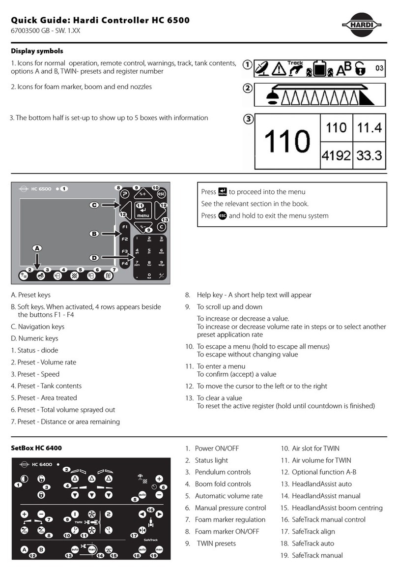
A. Preset keys:
Vital information while spraying is quick and easy to access. With just
one preset key press, information is shown in the lower left corner of
display.Pressingthesamebutton twicewillshowgraphicinformation
of the same readout on volume rate and speed.
B. Soft keys:
Soft keys control optional features. Pressing a soft key will activate it.
When any of the 4 soft keys (F1, F2, F3 or F4) are pressed, the soft key
menuappearsin the“largeright”area. Thenumber oflevelsinthesoft
key menu system depends on the number of functions.
C. Navigation keys:
The navigation keys are initially used for set up in the menu system by
coding in values. The navigation keys can change the volume rate in a
set percentage or fixed volume rate.
| is used to clear a value or register.
~ is used to escape back to your working screen.
© Is used if you have questions about the menu you are in. A short
help text will appear.
D. Numeric keys:
Theseareverymuchlikeamobilephone.Itisveryeasytoentertextlike
a field name. They are also used to key in a value or directly access a
menu.
The numeric keys are used when a name or a number is keyed in.
Help key
Thehelpkeyisalwaysactive.Itistheoperator’sbuilt-inquickguideand
instruction manual. After the help key has been activated, an
explanation of any control key orswitch is shown on a full screen.
Furthermore, if a message, warning or service reminder appears, more
details are found by pressing the help key. This will free the operator
from finding details in the instruction manual.
Press © to activate help text.
Press © to leave help function.

3 - Description
3.6
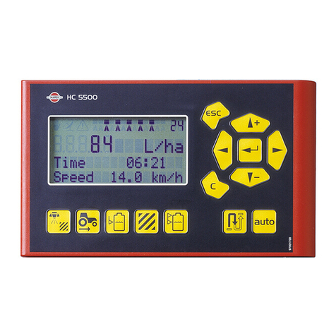
Terminal HC 6500
1. Status diode.
2. Preset key - Volume rate.
3. Preset key - Speed.
4. Preset key - Tank contents.
5. Preset key - Area treated.
6. Preset key - Total volume sprayed out.
7. Preset key - Distance or area remaining.
8. Help key.
9. Scroll up or down, change a value or volume rate.
10. Escape a menu.
11. Enter menu or confirm a value.
12. Move cursor to right or left.
13. Clear a value.
Icons for status:
Night illumination
Itispossibletochoosebetweendayandnightillumination.Gotomenu
[2.7.1 Choose day/night colors] for selection. Picture shows night
illumination.
Volume rate
Automatic Warning Track Crab
right Option B on Pendulum
Locked
Volume rate
Manual Information TWIN Manual Options both
on Pendulum
Unlocked
Variable rate
(GPS) active Track
Automatic TWIN Preset 1 Not used in
North America Not used in
North America
All “OK” Track Manual TWIN Preset 2 Not used in
North America Not used in
North America
Stop (critical) Track Lock Option A on Not used in
North America Not used in
North America
Track Crab left Options both
off Not used in
North America Not used in
North America
Not used in
North America Over or under
application

3 - Description
3.7
SetBox HC 6400
The SetBox controls secondary functions. The keys are large so even at
a distance, operation can be carried out. The keys are grouped into
control areas to simplify operator understanding.
1. Power ON/OFF.
2. Status diode.
3. Pendulum lock controls.
4. Boom fold controls.
5. Automatic volume rate.
6. Manual pressure control.
7. Foam marker regulation.
8. Foam marker ON/OFF.
9. TWIN presets.
10. Air slot for TWIN.
11. Air volume for TWIN.
12. Valve function A-B.
13. Not used in North America.
14. Not used in North America.
15. Not used in North America.
16. SafeTrack manual control.
17. SafeTrack align.
18. SafeTrack automatic selection.
Grip HC 6300
TheGripisanergonomicremoteunitthatcanbeeasilymountedinside
the tractor cabin. All common functions required during normal
spraying can be operated with the Grip.
TheGripcannotbeswitchedONorOFFseparately.Itreceivesthepower
supplyfromtheTerminalHC6500.Itisthereforeautomaticallyswitched
ON or OFF with the Terminal.
1. Status diode.
2. Boom section controls (up to 13).
3. Main ON/OFF.
4. Tilt.
5. Boom height.
6. Boom slant.
7. TWIN presets.

3 - Description
3.8
Display symbols
1. The 1st Line is for status and register number.
2. The 2nd Line is for boom, foam marker and end nozzles
3. The bottom half can be set-up to show 1 or 2 and up to 5 boxes
with information.
Soft keys: When activated 4 rows appear beside the buttons F1 - F4.
Alarm and warning error number will be shown in the upper right
cornerofthedisplay.The numberhasan exclamationsign infrontofit,
as this is also used for register number indication.
General keystrokes, daily settings
Press # to enter the menu system.
Note that the menu numbers are unique to each line or page.
When adjustments are made in settings, the display will be as shown.
The two markings > > show the actual menu where you are located. It
isnowpossibletogoupanddownbyusingthe¿andªkeys,orby
pressingthemenuslastdigitatthenumerickeypad;e.g.pressing“6”for
menu [4.6 Speed simulation].
The last value which was used, is marked with this symbol ‰. In the
bottomofthe display therewillbe helptextforeach menu.Whereyou
see the two > > you will see the help text for that menu only.
This display setup will be shown every time adjustments have to be
made in the menu.
4 TOOLBOX
>> 4.1 Measure
4.2 Service interval: Hours until
4.3 Stop-watch
4.4 Alarm clock
4.5 Test
4.6 Speed simulation
4.7 Emergency track Align
4.8 Computer CAN status
To measure distance and area.
Setup working width
Other manuals for HC 6500
1
Table of contents
Other Hardi Controllers manuals
Hardi
Hardi HC5500 User manual

Hardi
Hardi HC 9600 User manual
Hardi
Hardi HC 5500 SPRAY BOX III User manual
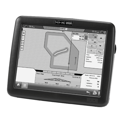
Hardi
Hardi ISOBUS VT User manual

Hardi
Hardi HC5500 User manual

Hardi
Hardi HC5500 User manual
Hardi
Hardi HC 8500 User manual

Hardi
Hardi HC5500 User manual

Hardi
Hardi HC5500 User manual

Hardi
Hardi HC 2500 Series User manual
Popular Controllers manuals by other brands
Metal Work
Metal Work SHAK 470 Use and maintenance manual
Johnson Controls
Johnson Controls penn TC3B21 installation guide
GE
GE Becker VRP-B-CH Series instruction manual

SunMaxx Solar
SunMaxx Solar SmartMaxx-Pro-XL6D installation guide

Emerson
Emerson FL instruction manual

ABB
ABB Advant Controller 450 Product guide

