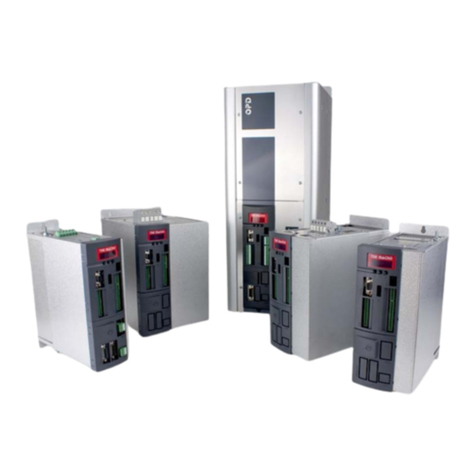
TDE MACNO MINIOPD EXP User manual

© TDE Macno SPA - Cod. MAOPDEV010E0 rev. 3.2
MINIOPD EXP - OPD EXP
USER’S MANUAL - ASYNCHRONOUS
MINIOPD EXP - OPD EXP
USER’S MANUAL - ASYNCHRONOUS
EN
Tecnologie Digitali Elettroniche S.p.A.


3
User’s manual
SOMMARY
1Introduction .............................................................................................5
1.1Parameters (P)........................................................................................................................ 5
1.2Connections (C) ...................................................................................................................... 5
1.3Input logic functions (I) ............................................................................................................ 6
1.4Internal values (D)................................................................................................................... 6
1.5Output logic functions (o) ........................................................................................................ 6
2ASYNCHRONOUS PARAMETERS........................................................7
2.1DRIVE AND MOTOR COUPLING........................................................................................... 7
2.1.1DRIVE PLATE ................................................................................................................ 7
2.1.2MOTOR PLATE.............................................................................................................. 8
2.1.3MOTOR SENSOR.......................................................................................................... 9
2.1.4AUTOTUNING CONTROL AND MOTOR MEASURED MODEL ................................. 11
2.1.5Identifying models of induction motor ........................................................................... 19
2.2MOTOR CONTROL .............................................................................................................. 23
2.2.1Acceleratio ramps and speed limit................................................................................ 24
2.2.2Speed COntrol.............................................................................................................. 26
2.2.3Torque and current limits.............................................................................................. 29
2.2.4Current control.............................................................................................................. 32
2.2.5Voltage/Flux control...................................................................................................... 33
2.3Protection.............................................................................................................................. 35
2.3.1Voltage limits ................................................................................................................ 35
2.3.2Thermal protection ....................................................................................................... 42
2.4V/F control............................................................................................................................. 44
2.4.1Automatic Setting of working Voltage/frequency .......................................................... 44
2.4.2Manual Setting of working Voltage/frequency characteristic ........................................ 45
2.4.3Load effect compensation ............................................................................................ 47
2.4.4Particular control functions ........................................................................................... 48
3Standard application .............................................................................49
3.1Input ...................................................................................................................................... 49
3.1.1Analog reference .......................................................................................................... 49
3.1.2Digital speed reference ................................................................................................ 53
3.1.3Frequency speed reference.......................................................................................... 55
3.1.4Digital inputs configurations.......................................................................................... 61
3.1.5Second sensor ............................................................................................................. 62
3.2OUTPUT ............................................................................................................................... 63
3.2.1Digital output configurations ......................................................................................... 63
3.2.2Analog outputs configurations ...................................................................................... 64
3.2.3Frequency OUTPUT..................................................................................................... 67
3.3MOTION CONTROL ............................................................................................................. 71
3.3.1Incremental position loop ............................................................................................. 71

4
3.3.2PID controller................................................................................................................ 73
4Fieldbus ................................................................................................76
4.1MODBUS parameters ........................................................................................................... 76
4.1.1Application Configuration.............................................................................................. 76
4.1.2Managed services ........................................................................................................ 77
4.2Can open............................................................................................................................... 80
4.2.1Configuration of the application .................................................................................... 80
4.2.2Managed services ........................................................................................................ 81
4.2.3Emergency Object (EMCY) .......................................................................................... 83
4.2.4Network Management Objects (NMT) .......................................................................... 83
4.2.5Objects dictionary : communication profile area .......................................................... 84
4.2.6Objects’ dictionary : manufacturer specific profile area ................................................ 85
5Generic parameters ..............................................................................92
5.1keys....................................................................................................................................... 92
5.2Data storing........................................................................................................................... 92
5.2.1Storage and recall of the working parameters ............................................................. 92
5.3Digital commands and control ............................................................................................... 94
5.3.1Drive ready ................................................................................................................... 94
5.3.2Drive switch on / RUN .................................................................................................. 94
5.3.3Drive switch off / STOP ................................................................................................ 95
5.3.4Safety Stop................................................................................................................... 95
6Alarms ..................................................................................................96
6.1Maintenance and controls ..................................................................................................... 96
6.1.1Malfunctions without an alarm: troubleshooting............................................................ 96
6.1.2Malfunctions with an alarm: troubleshooting................................................................. 97
7Display................................................................................................101
7.1Physical disposition............................................................................................................. 101
7.2Layout of the internal dimensions........................................................................................ 101
7.2.1Parameters (par) ........................................................................................................ 102
7.2.2Application Parameters (app) ..................................................................................... 103
7.2.3Connections (con) ...................................................................................................... 103
7.2.4allarmS (all) ................................................................................................................ 104
7.2.5Internal Values (int) .................................................................................................... 105
7.2.6Logic functions of input (inp)....................................................................................... 105
7.2.7Logic Functions of output (OUt).................................................................................. 106
7.3status of rest........................................................................................................................ 106
7.4Main Menu .......................................................................................................................... 107
7.4.1Under-Menu of parameters, application parameters and connections management
(par, app e con)......................................................................................................................... 108
7.4.2Visualization of the internal dimensions (INT) ............................................................ 110
7.4.3Alarms (ALL) .............................................................................................................. 110
7.4.4visualization of the input and output (inp and out) ...................................................... 111
7.5Programming Key ............................................................................................................... 113
8List of parameters...............................................................................114

5
User’s manual
1 INTRODUCTION
To help the customer during the configuration of the drive, the manual is organized to follow faithfully
the structure of the configurator (OPDExplorer) that allows, according to a logical sequence, to set all
the sizes needed for the proper functioning of the drive.
In particular, each chapter refers to a specific folder of OPDExplorer which includes all the relative
parameters.
Also, at the beginning of each chapter of the manual, is showed the location of the folder in the
OPDExplorer tree, which the chapter refer, and the complete table of sizes of the folder in question.
The control values are divided as follows:
•Parameters
•Connections
•Input logic functions
•Internal values
•Output logic functions
In the tables of the control value, the last column on the right “Scale” shows the internal
representation base of the parameters. This value is important if the parameters have to be read or
written with a serial line or fieldbus and represent the factor which to divide the value stored to
obtain the real value set, as following indicated:
Examples:
MAIN_SUPPLY ÆP87 – Main supply voltage
Value = 400
Scale = 10
Int. rep. = 4000
1.1 PARAMETERS (P)
The parameters are drive configuration values that are displayed as a number within a set range. The
parameters are mostly displayed as percentages, which is especially useful if the motor or drive size
have to be changed in that only the reference values (P61÷P65) have to be modified and the rest
changes automatically. The parameters are split up into free, reserved and TDE MACNO reserved
parameters.
The following rules apply:
Free parameters (black text in OPDExplorer): may be changed without having to open any key, even
when running;
Reserved parameters (blu text in OPDExplorer): may be changed only at a standstill after having
opened the reserved parameter key in P60 or the TDE MACNO reserved parameters key in P99;
TDE MACNO reserved parameters (violet text in OPDExplorer): may be changed only at a
standstill after having opened the TDE MACNO reserved parameters key in P99. While the key for
these parameters is closed, they will not be shown on the display.
Take careful note of the reference values for each parameter so that they are set correctly.
1.2 CONNECTIONS (C)
The connections are drive configuration values that are displayed as a whole number in the same
way as a digital selector.

6
They are split up into free, reserved and TDE MACNO reserved connections, and are changed in the
same way as the parameters.
The internal representation base is always as whole number
1.3 INPUT LOGIC FUNCTIONS (I)
The input logic functions are 32 commands that come from configured terminal board logic inputs,
from the serial line, and from the fieldbus. The meaning of this logical functions depend on the
application, so please refer to specific documentation.
1.4 INTERNAL VALUES (D)
Internal values are 128 variables within the drive that can be shown on the display or via serial on the
supervisor. They are also available from the fieldbus.
The first 64 values are referred to motor control part and are always present. The second 64 values
are application specific.
Pay close attention to the internal representation base of these values as it is important if readings
are made via serial line or fieldbus.
1.5 OUTPUT LOGIC FUNCTIONS (O)
The logic functions are 64, the first 32 display drive status and second 32 are application specific.
All output functions can be assigned to one of the 4 logic outputs.

7
User’s manual
2 ASYNCHRONOUS PARAMETERS
The “Asyncrhonous Parameters” are used to control the current or speed of a feedback vector
induction motor. The speed and current reference values are generated by the application. See the
application parameters for further information. As an absolute position value is not required for the
sensors (managed with an optional internal electronic board) incremental TTL Encoders and
incremental Sin/Cos Encoders may be used. Absolute sensors such as Resolver can also be used,
as can digital sensors such as Endat or Hiperface if required.
The “Asyncrhonous Parameters” also manages the auto-tuning test, which is crucial if the control is
to adapt perfectly to the motor and to ensure excellent dynamic performance all-round.
2.1 DRIVE AND MOTOR COUPLING
This section is usefull during motor start-up to obtain the best coupling between drive and
motor. It’s very important to follow the correct sequence explained in the next paragraphs
2.1.1 DRIVE PLATE
Name Description Min Max Default UM Scale
MAIN_SUPPLY P87 - Main Supply
voltage 180.0 780.0 400 V rms 10
DRV_I_NOM P53 - Rated drive current 0.0 3000.0 0 A 10
DRV_I_PEAK P113 - Maximum drive
current 0.0 3000.0 0 A 10
I_OVR_LOAD_SEL C56 - Current overload 0 3 3 1
PRC_DRV_I_MAX P103 - Drive limit current 0.0 800.0 200 % DRV_I_NOM 40.96
DRV_F_PWM P101 - PWM frequency 1000 16000 5000 Hz 1
DRV_F_PWM_CARATT P156 - PWM frequency
for drive definition 1000 16000 5000 Hz 1
DRV_E_CARATT P167 - Characterization
voltage 200.0 690.0 400 V rms 10
DEAD_TIME P157 - Dead time
duration 0.0 20.0 4 µs 10
T_RAD P104 - Radiator time
constant 10.0 360.0 80 s 10
T_JUNC P116 - Junction time
constant 0.1 10.0 3.5 s 10
OVR_LOAD_T_ENV
P155 - Ambient
temperature reference
value during overload
0.0 150.0 40 °C 10
This parameters are related to the drive characteristic. The user has to set only the main supply
voltage and select the current overload.

8
2.1.1.1 DRIVE CURRENT OVERLOAD SELECTION
Four types of drive overload can be set on C56
NB: the choice also changes the rated drive current as shown by the tables in the installation file and
the correct value is always displayed in ampere rms in P53.
The delivered current is also used to calculate the operating temperature reached by the power
component junctions with the drive presumed to be working with standard ventilation at the maximum
ambient temperature permitted.
If this temperature reaches the maximum value permitted for the junctions, the delivered power limit
is restricted to a value that is just over the rated drive current, i.e. the system’s effective thermal
current (see following table).
Now the drive will only overload if the temperature drops below the rated value, which will only occur
after a period of operation at currents below the rated current.
The junction temperature calculation also considers the temperature increase that occurs while
operating at low frequencies (below 2.5 Hz) due to the fact that the current is sinusoidal and thus has
peak values that are higher than the average value. With electrical operating frequencies lower than
2.5Hz, the drive goes into maximum overload for 20-30ms after which the maximum current limit is
reduced by √2 as shown by the following table:
N.B. = the overload time illustrated is calculated with the drive running steady at the rated motor
current. If the average delivered current is lower than the rated motor current, then the overload time
will increase. Thus the overload will be available for a longer or identical time to the ones shown.
N.B. 3٭= the 200% overload is available until junction temperatures are estimated to be 95% of the
rated value; at the rated value the maximum limit becomes 180%. For repeated work cycles, TDE
MACNO is available to estimate the drive’s actual overload capacity
2.1.2 MOTOR PLATE
Name Description Min Max Default UM Scale
PRC_MOT_I_NOM P61 - Rated motor
current ( I NOM MOT) 10.0 100.0 100 % DRV_I_NOM 327.67
MOT_V_NOM P62 - Rated motor
voltage 100.0 1000.0 380 Volt 10
MOT_F_NOM P63 - Rated motor
frequency 10.0 800.0 50.0 Hz 10
PRC_MOT_V_MAX P64 - Max. operating
voltage 1.0 200.0 100 % MOT_V_NOM 40.96
C56 Overload type for rated drive current (P53)
0 120% for 30 seconds
1 150% for 30 seconds
2 200% for 30 seconds
3 200% for 3 seconds and 155% for 30 seconds
C56 Max. drive current Drive thermal current Limit below 2.5 Hz
0 120% I NOM AZ for 30 seconds 103% I NOM AZ 84% I NOM AZ
1 150% I NOM AZ for 30 seconds 108% I NOM AZ 105% I NOM AZ
2 200% I NOM AZ for 30 seconds 120% I NOM AZ 140% I NOM AZ
3٭
200% I NOM AZ for 3 seconds
155% I NOM AZ for 30 seconds
110% I NOM AZ 140% I NOM AZ

9
User’s manual
Name Description Min Max Default UM Scale
MOT_SPD_MAX P65 - Max. operating
speed (n MAX) 50 60000 2000 RPM 1
MOT_COS_PHI P66 - Nominal power
factor 0.500 1.000 0.894 1000
MOT_POLE_NUM P67 - Number of motor
poles 1 12 4 1
PRC_MOT_I_THERM P70 - Motor thermal
current 10.0 110.0 100 % PRC_MOT_I_NOM 10
MOT_TF_THERM P71 - Motor thermal time
constant 30 2400 180 s 1
Setting the parameters that establish the exact type of motor used is important if the drive is to run
correctly. These parameters are:
Name Description
PRC_MOT_I_NOM P61 - Rated motor current ( I NOM MOT)
MOT_V_NOM P62 - Rated motor voltage
MOT_F_NOM P63 - Rated motor frequency
MOT_POLE_NUM P67 - Number of motor poles
These parameters are fundamental in that they are the basis of all the motor operating
characteristics: frequency, speed, voltage, current, torque and thermal protection.
P62 and P63 can be read directly on the motor rating plate and P61 can be calculated with the
following formula:
P61 = (Inom_motor *100.0))/(Inom_drive)
Example: Drive: OPEN 22
Inom_drive = 22A overload 200%
Motor: MEC series, Vn = 380V, f = 50Hz, Inom_motore = 20A,
P61 = (20*100)/22 = 90.9%
P62 = 380.0
P63 = 50.0
There are also parameters that establish the maximum values for voltage, thermal current and
operating speed:
Name Description
PRC_MOT_V_MAX P64 - Max. operating voltage
MOT_SPD_MAX P65 - Max. operating speed (n MAX)
PRC_MOT_I_THERM P70 - Motor thermal current
MOT_TF_THERM P71 - Motor thermal time constant
These important parameters must be specified alongside the exact characteristics of the feedback
sensor used. Once the sensor has been established, the “Sensor and motor pole tests”can be
carried out (enabled with C41) which will confirm that the parameters have been set correctly.
2.1.3 MOTOR SENSOR

10
Name Description Min Max Default UM Scal
e
SENSOR_SEL C00 - Speed sensor
Range
1 1
1 Encoder
4 Resolver
5 Resolver RDC
8 Sin/Cos incr
RES_POLE P68 - Number of absolute sensor
poles 1 12 2 1
ENC_PPR P69 - Number of encoder
pulses/revolution 0 60000 1024 pulses/rev 1
EN_TIME_DEC_ENC C74 - Enable incremental encoder
time decode 0 1 0 1
RES_TRACK_LOOP_BW P89 - Tracking loop bandwidth
direct decoding of resolver 100 10000 1800 rad/s 1
RES_TRACK_LOOP_DAMP P90 - D Traking loop bandwidth 0.00 5.00 0.71 100
RES_CARR_FRQ_RATIO C67 - Resolver carrier frequency
Range
0 1
-3 f PWM
÷
8
-2 f PWM
÷
4
-1 f PWM
÷
2
0 f PWM
1 f PWM x 2
2 f PWM x 4
3 f PWM x 8
EN_SENSOR_TUNE C68 - Enable sensor auto-tuning 0 1 0 1
EN_INV_POS_DIR C76 - Invert positive cyclic versus 0 1 0 1
KP_SINCOS1_CHN
P164 - Resolver or Incremental
Sin/Cos sine and cosine signal
amplitude compensation
0.0 200.0 100 % 163.8
4
OFFSET_SIN1 P165 - Resolver or Incremental
Sin/Cos sine offset -16383 16383 0 1
OFFSET_COS1 P166 - Resolver or Incremental
Sin/Cos cosine offset -16383 16383 0 1
OFFSET_SINCOS_ENC D38 - Compensation Sin/Cos
analog/digital term 0 pulses 1
SENSOR_FRQ_IN D39 - Input frequency 0 kHz 16
HW_SENSOR1 D63 - Sensor1 presence 0 1
SENS1_ZERO_TOP D55 - Sensor1 Zero Top 0 pulses 1
EN_SINCOS_PREC_POS C70 - Enable SinCos Analog-
Digital compensation into position 0 1 0 1
For correct motor sensor setup is necessary to set the motor sensor present:
Name Description
SENSOR_SEL C00 - Speed sensor
and, for the specific sensor present, the following parameters.
For the TTL encoder and the incremental sin-cos encoder:
And for the resolver:
After that is necessary proceed with the auto tuning procedure.
Name Description
ENC_PPR P69 - Number of encoder pulses/revolution
Name Description
RES_POLE P68 - Number of absolute sensor poles
RES_CARR_FRQ_RATIO C67 - Resolver carrier frequency

11
User’s manual
2.1.3.1 FINE SETUP MOTOR SENSOR
For some kind of sensor, after the auto tuning procedure is possible set some sensor parameter to
increase the performance.
2.1.3.1.1 FINE SETUP FOR RESOLVER
The fine tuning resolver setup allows to set, with a semiautomatic procedure, any offset
and a multiplicative factor to adjust the signals acquired by the resolver channels in order
to increase system performance.
The procedure begins by setting C68 = 1 and giving a reference speed that the motor can
run at 150 rpm.
The motor have to run for about 30 seconds after stop the test is completed.
Automatically updates the values of P165 and P166 (offset) and P164 (multiplication factor
to adjust the amplitude)
2.1.3.1.2 FINE SETUP FOR INCREMENTAL SIN/COS ENCODER
The fine tuning incremental sin/cos encoder setup allows to set, with a semiautomatic
procedure, any offset and a multiplicative factor to adjust the signals acquired by the
incremental sin/cos encoder channels in order to increase system performance.
The procedure begins by setting C68 = 2 and giving a reference speed that the motor can
do one o two turns .
After stop the test is completed.
Automatically updates the values of P165 and P166 (offset) and P164 (multiplication factor
to adjust the amplitude)
2.1.4 AUTOTUNING CONTROL AND MOTOR MEASURED MODEL

12
Name Description Min Max Default UM Scale
EN_TEST_CONN C41 - Enable sensor and
motor phase tests 0 1 0 1
PRC_I_TEST_CONN
P114 - Current in
connection tests for UVW,
Poles and reading Rs
0.0 100.0 100 % DRV_I_NOM 327.67
EN_AUTOTUNING C42 - Enable auto-tunings
Range
0 1
0 No
1 Test 1 and 2
2 Test 3 and 4
3 All
DIS_DEF_START_AUTO C75 - Disable Autotuning
starting from default values 0 1 0 1
TEST3-4_ACC_TIME P121 - Test 3 and 4
acceleration time 0.01 199.99 6.8 s 100
PRC_I_TEST_DELTA_VLS P129 - Test current to
establish VLS 0.0 100.0 30.0 % 327.67
TEST_CONN_FEEDBACK
P79 - Connection tests:
Encoder: pulses counted,
Resolver or Sin Cos Enc:
time reading
-19999 19999 0 0
EN_TEST_SPD C53 - Enable test of start-up
time
Range
0 1
0 Not enabled
1 Start up
2 Step
TEST_SPD_T_MAX P130 - Torque during start-
up test 0.0 100.0 100 % MOT_T_NOM 40.96
TEST_SPD_MAX P132 - Speed during start-
up test -100.00 100.00 100 % MOT_SPD_MAX 163.84
TEST_SPD_SPACE_MAX
P134 - Maximum
revolutions during start-up
test
0.00 3000.0 100 revolutions 10
PRC_MOT_FRICTION P136 - Friction torque 0.0 100.0 0 % MOT_T_MOM 40.96
START_TIME P169 - Start up time 0 19999 10 ms 1
Speed test are useful for measure total system inertia and to set correctly speed regulator gains.
For safety reasons it’s possible to limit maximum speed test with parameter P130, maximum motor
torque with parameter P132 and maximum space admitted for test with P134 revolutions.
The drive doesn’t go over these limits during test execution.
2.1.4.1 START-UP TIME
Start-up time is defined like the time needed to reach maximum speed (P65) with nominal motor
torque.
This autotest is useful to measure total system inertia and frictions.
For enable this test set C53=1 (EN_TEST_SPD = 1 Start Up). In the display appears “Auto”.
Give the run command and automatically the motor starts to move and than return to zero speed.
At this point switch off the run command. Parameter P169 is set with the start-up time in milliseconds,
parameter P136 is set with friction measured in percent of motor nominal torque.
Automatically C53 is cleared to 0 and the test is finished.
If the space admitted is enough the speed profile is trapezoidal:

13
User’s manual
Otherwise:
T_RIF=TEST_SPD_T_MAX (P130)
T_RIF= - TEST_SPD_T_MAX (P130)
time
T_RIF=TEST_SPD_T_MAX (P130)
T_RIF= - TEST_SPD_T_MAX (P130)
SPD_RIF=TEST_SPD_ MAX (P132)
time

14
2.1.4.2 STEP RESPONSE
Step response is a common mode to test speed loop stability and dynamic performance.
For enable this test set C53=2 (EN_TEST_SPD = 2 Step). In the display appears “Auto”.
At this point all speed reference are ignored, instead a fixed speed reference is calculated equals to
maximum test torque (P130) divided by speed regulator proportional gain. In this way giving this step
speed reference, the torque requested doesn’t go over maximum torque admitted.
Linear ramps are automatically disabled. Giving the run command, motor starts and try to follow the
reference with its dynamic performance.
Evaluating the speed response it’s possible to understand the system stability and speed loop
bandwidth.
With Real Time Graph is possible to see the motor speed response. Set:
Post Trigger Points = 90% Trigger Type = standard +03 Speed Reference
Trigger level = 1% Trigger slope = ascending
Sample Time = 1
Channels = 2
Channel A = Standard - o03 Reference speed value after ramps
Channel B = Standard - o49 Rotation speed not filtered
Set speed regulator gain and look the step response. Try and repeat until the speed response has
good stability and bandwidth.
Motor runs at constant speed until the run command is on.
Switch off the run command to stop the motor and start a new test.
Step response test is finished only when C53 is manually clear to 0.
2.1.4.2.1 SPEED REGULATOR GAIN SETTING SUGGESTIONS
1. First of all disable integral part setting lead time constant P32 with a big value (>
500ms).
2. Try to find the best proportional gain P31 and filter time constant P33 to obtain a step
response with max overshoot of 20%. It’s important to evaluate also the acoustic and
electrical motor noise.
3. Reduce lead time constant P32 up to minimum value without increase the overshoot

15
User’s manual
The first step for the auto-tuning procedure is the sensor test.
After to set the correct parameters in the Motor sensor section is necessary to complete the auto-
tuning procedure for the sensor present and selected.
2.1.4.3 TTL ENCODER
2.1.4.3.1 SENSOR PARAMETERS
It’s necessary to have set correctly the parameter P69 in order to define the Encoder
2.1.4.3.2 SPEED SENSOR TEST
It is in two parts:
oCheck that the direction of rotation of the motor phases and the Encoder
correspond;
oCheck that the number of motor poles is written correctly in parameter P67 and the
Encoder used is correctly define as pulses per revolution with parameter P69
Correct operation requires a no-load motor so decouple it from the load.
Name Description Min Max Default UM Scale
PRC_MOT_T_MAX P41 - Maximum torque at full load 0.0 400.0 400.0 % MOT_T_NOM 40.96
MOT_COS_PHI P66 - Nominal power factor 0.500 1.000 0.894 1000
PRC_MOT_I_T_NOM P72 - Nominal torque current 5.0 100.0 95.2 % PRC_MOT_I_NOM 327.67
PRC_MOT_I_FLX_NOM P73 - Nominal flux current 5.0 100.0 30.2 % PRC_MOT_I_NOM 327.67
T_ROTOR P74 - Rotor time constant Tr 10 10000 182 ms 1
T_STATOR P75 - Stator time constant Ts 0.0 50.0 8.5 ms 10
PRC_DELTA_VRS P76 - Voltage drop due to stator
resistor 1.0 25.0 2.0 % MOT_V_NOM 327.67
PRC_DELTA_VLS P77 - Voltage drop due to leakage
inductance 5.0 100.0 20.0 % MOT_V_NOM 327.67
MOT_T_NOM P78 - Nominal motor torque 0.5 3000.0 0.0 Nm 10
PRC_DEAD_TIME_CMP P102 - Dead time compensation 0.0 100.0 22.0 ‰ PRC_MOT_V_MAX 32.76
MOT_V0 P128 - Voltage motor at nominal speed
with no load 0.0 100.0 100.0 % MOT_V_NOM 327.67
K_FLX45 P131 - Magnetic characteristic point 1 0.0 120.0 90.2 % 40.96
K_FLX55 P133 - Magnetic characteristic point 2 0.0 120.0 90.5 % 40.96
K_FLX65 P135 - Magnetic characteristic point 3 0.0 120.0 91.1 % 40.96
K_FLX75 P137 - Magnetic characteristic point 4 0.0 120.0 91.8 % 40.96
K_FLX82 P139 - Magnetic characteristic point 5 0.0 120.0 92.7 % 40.96
K_FLX88 P141 - Magnetic characteristic point 6 0.0 120.0 94.2 % 40.96
K_FLX93 P143 - Magnetic characteristic point 7 0.0 120.0 95.8 % 40.96
K_FLX97 P145 - Magnetic characteristic point 8 0.0 120.0 98.1 % 40.96
K_FLX100 P147 - Magnetic characteristic point 9 0.0 120.0 100.0 % 40.96
K_FLX102 P149 - Magnetic characteristic point 10 0.0 120.0 102.0 % 40.96
PRC_DEAD_TIME_CMP_XB P151 - Xb = cubic coupling zone
amplitude 0.0 50.0 0.0 % DRV_I_NOM 163.84
PRC_DEAD_TIME_CMP_YC P152 - Yc = compensation at rated
drive current 50.0 100.0 100 % DEAD_TIME_COMP 327.67
PRC_DEAD_TIME_CMP_X0 P153 - Xoo = dead zone amplitude 0.0 50.0 0 % DRV_I_NOM 163.84

16
After setting the drive to STOP and opening the reserved parameter key (P60=95), set C41=1 to
enable the test. To start the test enable RUN command with its digital input.
Once the test has started the motor will rotate in the positive direction at low speed and all Encoder
edges are counted.
During the test, the motor will make a complete revolution at low speed.
Do not worry if this revolution is a little noisy
In the first step is checked if the cyclic sense of motor phases and Encoder channels is the same:
after 1 second parameter P79 is updated with the test result and the drive consequently goes in
alarm A14 or
it starts the second test:
oP79=0 : meaning that is missing at least one Encoder channel, therefore A14 code
0 is triggered
oP79<0 : meaning that Encoder channels are exchanged, therefore A14 code 0 is
triggered
oP79>0 : everything is ok
In the second part is checked the Encoder pulses reading, well known from P69 parameter the
number of edges in a mechanical turn (P69x4, because are counted both two channels edge).
At the end of the test, P79 is updated again with the total edges number:
o|P79- (P69x4)|/(P69x4) < 12,5% : test is successful
otherwise the alarm A15 code 3 is triggered. In the first check if it is correct the
Encoder number of pulses per revolution and the number of motor poles.
oP79 < (P69x4): the real pulses counted are less than expected. Encoder could
have some problems or the motor load is too high. Try to increase the test current
with parameter P114 that is the percentage of rated drive current applied in the test
oP79 > (P69x4) : the real pulses counted are more than expected. Could be some
noise in the Encoder signals.
Note: for encoder with more than 8192 ppr the data showed in P79 loses of meaning
The test is successful if the drive switch off and does not trigger an alarm. Now disable RUN
command by setting its digital input to 0. The subsequent tests can now be carried out.
2.1.4.4 RESOLVER
2.1.4.4.1 SENSOR PARAMETERS
It’s necessary have to set correctly the parameter P68
Note: resolve poles number cannot be grater than motor poles number (P67), otherwise it is
triggered the alarm A15 with code 0.
2.1.4.4.2 SPEED SENSOR TEST
It is in two parts:
oCheck that the direction of rotation of the motor phases and the Resolver
correspond;
oCheck that the number of motor poles is written correctly in parameter P67 and the
Resolver used is correctly define as poles number with parameter P68
Correct operation requires a no-load motor so decouple it from the load.

17
User’s manual
After setting the drive to STOP and opening the reserved parameter key (P60=95), set C41=1 to
enable the test. To start the test enable RUN command.
Once the test has started the motor will rotate in the positive direction at low speed and some
measure are done on Resolver signals.
During the test, the motor will make a complete revolution at low speed.
Do not worry if this revolution is a little noisy.
In the first step is checked if the cyclic sense of motor phases and Resolver channels is the same:
after 1 second parameter P79 is updated with the pulses number counted (there are 65536 pulses
every turn/Resolver polar couples) and the drive consequently goes in alarm A14 or it starts the
second test: oP79<0 : meaning that Resolver channels are exchanged, therefore A14 code 0 is
triggered
oP79>0 : everything is ok
In the second part is checked the Resolver channels reading, well known that current test frequency
is 0,5Hz the time needed for read again the same Resolver position is equal to:
numbercouplepolarResolver
numbercouplepolarMotor
2testtime ⋅= [seconds]
At the end of the test, P79 is updated again with the time test measured in ms:
o|P79- time test| < 500ms : test is successful
otherwise the alarm A15 code 3 is triggered. In the first check if it is correct the Resolver poles
number and the number of motor poles, with help of P79.
The test is successful if the drive switch off and does not trigger an alarm. Now disable RUN
command by setting its digital input to 0. The subsequent tests can now be carried out.
2.1.4.5 INCREMENTAL SIN COS ENCODER
2.1.4.5.1 SENSOR PARAMETERS
It’s necessary to have set correctly the parameter P69
2.1.4.5.2 SPEED SENSOR TEST
. It is in two parts:
oCheck that the direction of rotation of the motor phases and the Encoder
correspond;
oCheck that the number of motor poles is written correctly in parameter P67 and the
Encoder used is correctly define as pulses per revolution with parameter P69
Correct operation requires a no-load motor so decouple it from the load.
After setting the drive to STOP and opening the reserved parameter key (P60=95), set C41=1 to
enable the test. To start the test enable RUN command.
Once the test has started the motor will rotate in the positive direction at low speed and all Encoder
edges are counted.
During the test, the motor will make a complete revolution at low speed.
Do not worry if this revolution is a little noisy
In the first step is checked if the cyclic sense of motor phases and Encoder channels is the same:
after 1 second parameter P79 is updated with the test result and the drive consequently goes in
alarm A14 or

18
it starts the second test:
oP79=0 : meaning that is missing at least one Encoder channel, therefore A14 code
0 is triggered
oP79<0 : meaning that Encoder channels are exchanged, therefore A14 code 0 is
triggered
oP79>0 : everything is ok
In the second part is checked the Encoder pulses reading, well known from P69 parameter the
number of edges in a mechanical turn (P69x4, because are counted both two channels edge).
At the end of the test, P79 is updated again with the total edges number:
o|P79- (P69x4)|/(P69x4) < 12,5% : test is successful
otherwise the alarm A15 code 3 is triggered. In the first check if it is correct the
Encoder number of pulses per revolution and the number of motor poles.
oP79 < (P69x4): the real pulses counted are less than expected. Encoder could
have some problems or the motor load is too high. Try to increase the test current
with parameter P114 that is the percentage of rated motor current applied in the
test (default value 50%).
oP79 > (P69x4) : the real pulses counted are more than expected. Could be some
noise in the Encoder signals.
The test is successful if the drive switch off and does not trigger an alarm. Now disable RUN
command. The subsequent tests can now be carried out
2.1.4.6 AUTO-TUNING PROCEDURES
2.1.4.6.1 SENSOR TESTS
This is the first test to be carried out. It is in two parts:
oCheck that the direction of rotation of the motor phases and the sensor correspond;
oCheck that the number of motor poles is written correctly in parameter P67 and the
speed sensor used is set correctly.
Correct operation requires a no-load motor so decouple it from the load.
After setting the drive to STOP and opening the reserved parameter key (P60=95), set C41=1 to
enable the test. The following setting will appear on the display:
The drive is now ready to start the test. To start reading, enable RUN with its digital input or working
with connection C21 (commands in series)Once the test has started, this setting will appear on the
display:
and the motor will rotate in the positive direction first to ensure the direction matches and will then
rotate again to ensure the motor phases and the sensor are set correctly.
During the test, the motor will make a complete revolution at low speed.
Do not worry if this revolution is a little noisy.
If the drive sets off an alarm during the test, an error has occurred. Check to see which alarm has
been triggered and deal with the problem accordingly:
oIf A14 code=1 is enabled, the test current is too low, check if the motor phases are
correctly connected to the drive

19
User’s manual
oIf A14 code=0 is enabled, connections U,V,W do not match the internal phases of
the drive. Invert two phases and repeat the test.
oIf A15 code=3 is enabled, the values set do not comply with the motor pole and
sensor settings.
At the end of the test, check parameter P79 as it may give some indication as to the problem. See
the “Feedback Option” file for the meaning of P79 as it depends on which sensor is used.
The test is successful if this setting appears on the display:
and the drive does not trigger an alarm.
Now disable RUN by setting its digital input to 0 or clearing C21.
The subsequent tests can now be carried out.
2.1.4.6.2 FINE SENSOR SETUP
After the first part of the autotunning, in some case, is possible to set some parametes regarding the
sensor to obtain a better system performance.
Dopo la prima parte dell’autotaratura, in alcuni casi, si possono settare alcuni parametri relativi al
sensore in modo da migliorare le prestazione del sistema:
2.1.4.6.3 ENCODER TIME DECODE
By default (C74=0) the speed is measuring counting the number of pulses in the PWM period.
This produces a poor resolution especially at low speed and the consequent need of signal filtering
(see the related core document, P33 parameter of speed regulator).
Setting C74=1 the speed calculation is done measuring the time between one Encoder pulse to the
other.
This technique has a maximum resolution of 12.5 ns, so the measure can be very accurate.
The Encoder time decode needs Incremental Encoder pulses with duty-cycle of 50%, a correct
pulses time distribution and the cables would be shielded very well
2.1.5 IDENTIFYING MODELS OF INDUCTION MOTOR
2.1.5.1 MOTOR AUTO-TUNING PARAMETERS
Name Description
PRC_MOT_T_MAX P41 - Maximum torque at full load
MOT_COS_PHI P66 - Nominal power factor
PRC_MOT_I_T_NOM P72 - Nominal torque current
PRC_MOT_I_FLX_NOM P73 - Nominal flux current
T_ROTOR P74 - Rotor time constant Tr
T_STATOR P75 - Stator time constant Ts
PRC_DELTA_VRS P76 - Voltage drop due to stator resistor
PRC_DELTA_VLS P77 - Voltage drop due to leakage inductance
MOT_T_NOM P78 - Nominal motor torque
These parameters are extremely important for modelling the motor correctly so that it can be used to
its full potential. The best procedure for obtaining the correct values is the “Auto-tuning test”, which

20
is enabled with connection C42: this test must be carried out with the motor decoupled from the load.
Failure to do so may invalidate the results.
If the tests cannot be carried out for any reason, these values will have to estimated by reading the
motor plate and following these points:
•The magnetizing current value is sometimes shown on the motor plate under I0. In this case,
P73 = I0 / Inom motore. If this value is not available, it will have to be estimated: set P73 to a value
that supplies a no-load motor running at rated speed with a three-phase alternate voltage which is
effective but slightly lower than the rated motor voltage. Then change P73 until d18 displays a
value of about 96 - 97% .
•Once P73 is established, rated torque current P72 can be established as: 10022
−P73
•The rotor time constant (in seconds) can be calculated with the following formula:
P73
P72
fs
1
6,28
1
Tr ⋅⋅= with fs rated slip frequency. P74 = Tr in milliseconds
Establish fs by reading the rated slip value, usually in rpm, on the motor plate, then compare it
with the rated speed and multiply everything by the rated motor frequency.
Check P74 by forcing the motor to request a torque current:
- changing the speed reference value brusquely
- applying different loads to the motor
and observing the behaviour of the stator voltage module. If this value is correct, the voltage
should only vary slightly in the transient phase.
These other parameters are not as important and the default values may be left if more reliable data
are unavailable.
This test reads the basic electrical parameters that characterise the induction motor being used so
that it can be modelled according to the rotor magnetic flux. After these values have been
established, the PI regulators in the current and flux loops are self-set .
There are 4 test functions. Each requires a no-load motor, i.e. decoupled from the load, if they
are to function correctly.
Connection C42 is used to enable these tests. See the table below:
C42 Enabled function
0 No test enabled
1 Only Tests 1 and 2 enabled. Motor does not
need to be rotating.
2 Only Tests 3 and 4 enabled. Motor needs to be
rotating.
3 All tests enabled. Tests carried out in quick
succession.
The display will show the following setting according to which tests are enabled:
The drive is now ready to start the test. Start reading by enabling RUN with its digital input and
setting C21=1 (command in series).
Once the tests have started, this setting will appear alongside:
The test finishes successfully if this setting appears the following indicaton and the drive does not
trigger an alarm.
Now disable RUN by setting its digital input to 0 or clearing C21=0.
Test 1 and 2 enabled
Test 3 and 4 enabled
This manual suits for next models
1
Table of contents
Other TDE MACNO Controllers manuals
