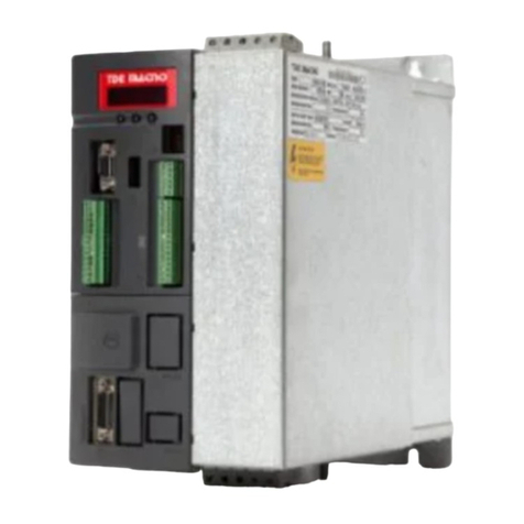
TDE MACNO DVS200 User manual

User Manual: operation, specifications
and connections
Torque control motor drives
DVS200
0,25 - 0,75 kW

Information in this manual is subject to change without notice, and is not therefore binding
on TDE Macno S.p.A. in any way.
ead the safety precautions section before installing, connecting up, starting up or setting
up the drive.
Keep this manual in a safe place where it is readily available to all technical personnel
throughout the drives working life.
TDE Macno S.p.A.declines all responsibility for any errors that may occur in this manual
and for any damage that may be incurred as a result.
All rights reserved.
Revision: 01.00
Software version: 0B.00-00.00
Edition date: 10/06/04

3
Key to Warning Symbols ............................................................................................................ 6
Chapter 1 - Safety Precautions ..................................................................................................7
1.1 Power and ground connections .......................................................................................................................................................
Chapter 2 - General Description ............................................................................................... 11
Standard functions ............................................................................................................................................................................. 12
Advanced functions available from the complete version .................................................................................................................... 12
Options .............................................................................................................................................................................................. 12
Chapter 3 - Description, Components and Specifications ....................................................... 13
3.1. Storage and transport ................................................................................................................................................................... 13
3.1.1. General .................................................................................................................................................................................... 13
3.1.2. Drive identification ................................................................................................................................................................... 14
3.1.3. Data plate ................................................................................................................................................................................. 14
3.2. Component identification ............................................................................................................................................................. 15
3.3. General specifications ................................................................................................................................................................. 16
3.3.1. Ambient conditions and standards ............................................................................................................................................. 16
Disposing of the drive ................................................................................................................................................................ 17
3.3.2. Mains input and drive output connections ................................................................................................................................. 1
3.3.3. Mains input current .................................................................................................................................................................. 18
3.3.4. Output ...................................................................................................................................................................................... 18
3.3.5. DVS regulation and control section ........................................................................................................................................... 19
3.3.6. Precision.................................................................................................................................................................................. 19
Chapter 4 - Installation ............................................................................................................. 20
4.1. Mechanical specifications ........................................................................................................................................................... 20
4.2. Installation distances ................................................................................................................................................................... 20
4.3. Motors ......................................................................................................................................................................................... 21
4.3.1. Asynchronous AC motors .......................................................................................................................................................... 21
Chapter 5 - Electrical Connections ........................................................................................... 23
5.1. Accessing the electrical terminals ............................................................................................................................................... 23
5.2. The power section ....................................................................................................................................................................... 24
5.2.2 Power terminal wire cross sections ........................................................................................................................................... 24
5.2.3. The rectifier bridge and intermediate circuit ............................................................................................................................. 25
5.2.3. The inverter bridge ................................................................................................................................................................... 25
5.3. The control section ...................................................................................................................................................................... 27
5.3.1. The A313-XX control card ......................................................................................................................................................... 2
5.3.2. Control card terminal identification ........................................................................................................................................... 28
5.4. The RS 485 serial interface .......................................................................................................................................................... 2
5.4.1. General .................................................................................................................................................................................... 29
5.5. Typical Connection Schematics .................................................................................................................................................... 30
5.5.1. DVS drive connections ............................................................................................................................................................. 30
5.5.2. Design constraints .................................................................................................................................................................... 30
5.5.3 Parallel mains AC input connections to more than one drive ....................................................................................................... 31
5.7. Chokes and filters ........................................................................................................................................................................ 32
5. .1. Mains input chokes .................................................................................................................................................................. 32
5. .2. Output chokes ........................................................................................................................................................................... 32
5. .3. Noise filters .............................................................................................................................................................................. 33
5.7.3.1 External EMI filter connections ....................................................................................................................................... 33
5.8. Braking ........................................................................................................................................................................................ 34
5. . Safety delay before work on the drive .......................................................................................................................................... 34
Chapter 6 - Using the Drives Control Keys ............................................................................. 35
6.1 Control keys and LEDs .................................................................................................................................................................. 35
6.2 Navigating the menus ................................................................................................................................................................... 36
6.5 Quick setup .................................................................................................................................................................................. 37

4
Chapter 7 - Parameter Description .......................................................................................... 38
7.1 Parameters List ............................................................................................................................................................................ 38
7.2 Menu d - DISPLAY ....................................................................................................................................................................... 57
Basic ................................................................................................................................................................................................. 5
Overload............................................................................................................................................................................................ 5
Inputs/Outputs .................................................................................................................................................................................... 58
Pid .................................................................................................................................................................................................... 59
Alarm list ........................................................................................................................................................................................... 60
Drive Identification ............................................................................................................................................................................. 60
Utility................................................................................................................................................................................................. 61
7.3 Menu S - START-UP ..................................................................................................................................................................... 62
Power Supply .................................................................................................................................................................................... 62
V/F Ratio .......................................................................................................................................................................................... 62
Motor Data ........................................................................................................................................................................................ 63
Commands & Referencies .................................................................................................................................................................. 64
Functions ........................................................................................................................................................................................... 65
Utility................................................................................................................................................................................................. 6
7.4 Menu I - INTERFACE .................................................................................................................................................................... 68
Digital Inputs Regulation Board .......................................................................................................................................................... 68
Digital Ouputs Regulation Board ......................................................................................................................................................... 69
Analog Inputs Regulation Board ......................................................................................................................................................... 0
Enabling Virtual I/O ............................................................................................................................................................................ 2
Serial Configuration ........................................................................................................................................................................... 5
7.5 Menu F - FREQ & RAMPS ............................................................................................................................................................ 78
Motorpotentiometer ........................................................................................................................................................................... 8
Reference Limits ................................................................................................................................................................................ 9
Reference Sources ............................................................................................................................................................................ 80
Multispeed Function .......................................................................................................................................................................... 81
Ramp Configuration ........................................................................................................................................................................... 82
Jump Frequencies ............................................................................................................................................................................. 84
7.6 Menu P - PARAMETERS............................................................................................................................................................... 86
Commands ........................................................................................................................................................................................ 86
Power Supply .................................................................................................................................................................................... 89
Motor Data ........................................................................................................................................................................................ 90
V/F Curve .......................................................................................................................................................................................... 91
Ouput Frequency Limit ....................................................................................................................................................................... 92
Slip Compensation ............................................................................................................................................................................. 93
Boost ................................................................................................................................................................................................. 94
Automatic Flux Regulation .................................................................................................................................................................. 95
Anti Oscillation Function .................................................................................................................................................................... 95
SW Current Clamp ............................................................................................................................................................................. 95
Current Limit ...................................................................................................................................................................................... 95
DC Link Limit ...................................................................................................................................................................................... 9
Over Torque Alarm Configuration ........................................................................................................................................................ 98
Motor Overload Configuration ............................................................................................................................................................ 99
BU Configuration .............................................................................................................................................................................. 100
DC Brake Configuration .................................................................................................................................................................... 100
Autocapture function ........................................................................................................................................................................ 101
Undervoltage Configuration .............................................................................................................................................................. 102
Overvoltage Configuration ................................................................................................................................................................ 106
Autoreset Configuration .................................................................................................................................................................... 10
External Fault Configuration ............................................................................................................................................................. 10
Phase Loss Detection ....................................................................................................................................................................... 108
Voltage Reduction Configuration ...................................................................................................................................................... 108
Frequency Threshold ....................................................................................................................................................................... 109
Steady State Signalling .................................................................................................................................................................... 111
Heatsink Temperature Threshold....................................................................................................................................................... 111
PWM Setting ................................................................................................................................................................................... 112
Dead Time Compensation ................................................................................................................................................................. 112
Display Setting ................................................................................................................................................................................ 113
Protection ........................................................................................................................................................................................ 113
7.7 Menu A - APPLICATION ............................................................................................................................................................. 114
PID Setting ...................................................................................................................................................................................... 114

5
PID Gains ......................................................................................................................................................................................... 118
PID Limits ........................................................................................................................................................................................ 118
7.8 Menu C - COMMANDS ............................................................................................................................................................... 120
Basic ............................................................................................................................................................................................... 120
Alarm Register Reset ....................................................................................................................................................................... 120
External Key .................................................................................................................................................................................... 120
Tuning ............................................................................................................................................................................................. 121
7. Menu H - HIDDEN ...................................................................................................................................................................... 122
Virtual I/O Commands ...................................................................................................................................................................... 122
Parameters Reading Extension ......................................................................................................................................................... 123
Serial Link Commands ...................................................................................................................................................................... 124
Chapter 8 - Modbus RTU Protocol for DVS drives ................................................................ 125
8.1 Introduction ................................................................................................................................................................................. 125
8.2 The MODBUS Protocol ................................................................................................................................................................ 125
8.3 Message format .......................................................................................................................................................................... 125
8.3.1 The address ............................................................................................................................................................................ 125
8.3.2 The function code .................................................................................................................................................................... 125
8.3.3 CRC16 ..................................................................................................................................................................................... 126
8.3.4 Message synchronization ........................................................................................................................................................ 126
8.3.5 Serial line setting .................................................................................................................................................................... 126
8.4 Modbus functions for the drive .................................................................................................................................................... 127
8.4.1 Read Output Registers (03) ...................................................................................................................................................... 12
8.4.2 Read Input Registers (04) ........................................................................................................................................................ 128
8.4.3 Preset Single Register (06) ...................................................................................................................................................... 128
8.4.4 Read Status (0 )...................................................................................................................................................................... 128
8.4.5 Preset Multiple Registers (16) ................................................................................................................................................. 129
8.5 Error management ....................................................................................................................................................................... 12
8.5.1 Exception codes ...................................................................................................................................................................... 130
8.6 System configuration ................................................................................................................................................................... 130
Chapter - Troubleshooting ................................................................................................... 131
.1 Drive Alarm Condition .................................................................................................................................................................. 131
.2 Alarm Reset ................................................................................................................................................................................. 131
.3 List of Drive Alarm Events ........................................................................................................................................................... 131
Chapter 10 - EMC Directive, Declarations of EC-Conformity................................................ 133
Table of contents
Other TDE MACNO DC Drive manuals
