TDK-Lambada Z10-20 User manual

USER MANUAL
Series
This Manual Covers Models:
Z10-20 Z20-10 Z36-6 Z60-3.5 Z100-2
Z10-40 Z20-20 Z36-12 Z60-7 Z100-4
Z10-60 Z20-30 Z36-18 Z60-10 Z100-6
Z10-72 Z20-40 Z36-24 Z60-14 Z100-8
Programmable DC Power Supplies
200W/400W/600W/800W
Built-in USB, RS-232 & RS-485 Interface
IA710-04-01K

Concentration Values of Toxic and Hazardous Substances/Elements (wt%) Notes
Lead (Pb)
0.1wt%
Mercury (Hg)
0.1wt%
Cadmium (Cd)
0.1wt%
Hexavalent
Chromium
(Cr6+)
0.1wt%
Polybrominated
Biphenyls (PBB)
0.1wt%
Polybrominated Diphenyl
Ethers (PBDE)
0.1wt%
Case O O O O O O
Plastic panel O O O O O O
PCB's assembly X O O O O O
Inner metal parts O O O O O O
Inner cables O O O O O O
Accessories O O O O O O Provided in the package
O : Indicates that the concentration values of toxic and hazardous substances in all ”homogeneous materials” of respective parts and materials does not exceed the concentration limits
regulated by ”SJ/T 11363-2006 Requirements for Concentration Limits for Certain Hazardous Substances in Electronic Information Products”.
X : Indicates that the concentration value of a toxic or hazardous substance included in a ”homogeneous part” of a respective part or material exceeds the concentration limit regulated by
”SJ/T 11363-2006 Requirements for Concentration Limits for Certain Hazardous Substances in Electronic Information Products”.
Date of manufacture
Part Name Z+Series: Z200, Z400, Z600, Z800 POWER SUPPLY Product Weight Z200: 1.9Kg
Product Weight Z400: 1.9Kg
Product Weight Z600: 2.1Kg
Product Weight Z800: 2.1Kg
Information Concerning Inclusion of Toxic and Hazardous Substances
This information sheet was prepared based on People's Republic of China ”Management Methods for Controlling Pollution Caused by Electronic Information Products Regulation”and
”SJ/T 11364—2006 Marking for Control of Pollution Caused by Electronic Information Products”.
As People's Republic of China ”Management Methods for Controlling Pollution Caused by Electronic Information Products Regulation”is a different legislation from EU RoHS2 Directive
(2011/65/EU), inquiries concerning EU RoHS2 Directive (2011/65/EU) information should be done separately.

Table of Contents
WARRANTY............................................................................................................................................. 8
REGULATORY NOTICES....................................................................................................................... 9
SAFETY INSTRUCTIONS...................................................................................................................... 9
CHAPTER 1: GENERAL INFORMATION
1.1 User Manual Content .................................................................................................................. 13
1.2 Introduction ................................................................................................................................... 13
1.2.1 General Description ................................................................................................................................. 13
1.2.3 Features and Options ............................................................................................................................. 13
1.2.4 Multiple Output Power System ........................................................................................................ 14
1.2.5 Control via the USB or RS232/485 Communication Ports ................................................ 14
1.2.6 Analog Voltage Programming and Monitoring ..................................................................... 14
1.2.7 Parallel Operation ..................................................................................................................................... 14
1.2.8 Output Connections ............................................................................................................................... 14
1.2.9 Cooling and Mechanical Construction ........................................................................................ 14
1.3 Accessories ..................................................................................................................................... 15
1.3.1 General ............................................................................................................................................................. 15
1.3.2 Serial Link Cable ......................................................................................................................................... 15
1.3.3 Misc. Hardware ........................................................................................................................................... 15
1.3.4 AC Cables ........................................................................................................................................................ 15
1.3.5 Serial Port Cables........................................................................................................................................ 15
CHAPTER 2: SPECIFICATIONS
2.1 Z+200 Series Specifications....................................................................................................... 16
2.2 Z+400 Series Specifications ......................................................................................................20
2.3 Z+600 Series Specifications ...................................................................................................... 24
2.4 Z+800 Series Specifications.......................................................................................................28
2.5 Supplemental Characteristics.................................................................................................. 31
2.6 Z200W/400W/600W/800W Outline Drawing.....................................................................32
2.7 Z200W/400W/600W/800W Optional IEEE, Isolated Analog
Interface Outline Drawing .......................................................................................................33
2.8 Z200W/400W/600W/800W Front Panel Output Binding
Post/Socket Outline Drawing L/L2 .......................................................................................34
CHAPTER 3: INSTALLATION
3.1 General.............................................................................................................................................35
3.2 Preparation for Use......................................................................................................................35
3.3 Initial Inspection...........................................................................................................................35
3.4 Rack Mounting..............................................................................................................................35
3.5 Location, Mounting and Cooling ...........................................................................................36
3.6 AC Source Requirements...........................................................................................................36
3.7 AC Input Power Connection..................................................................................................... 36
3.7.1 AC Input Connector ..................................................................................................................................36
3.7.2 AC Input Cord ............................................................................................................................................... 37
3.8 Turn-On Checkout Procedure..................................................................................................37
3.8.1 General ............................................................................................................................................................. 37
3.8.2 Prior to Operation...................................................................................................................................... 37
3.8.3 Constant Voltage Check ........................................................................................................................ 38
3.8.4 Constant Current Check......................................................................................................................... 38
3.8.5 OVP Check...................................................................................................................................................... 38
3.8.6 UVL Check ...................................................................................................................................................... 38
3.8.7 Foldback Check........................................................................................................................................... 39

3.9 Connecting the Load.................................................................................................................. 39
3.9.1 Load Wiring.................................................................................................................................................... 39
3.9.2 Current Carrying Capacity ....................................................................................................................40
3.9.3 Wire Termination ........................................................................................................................................ 41
3.9.4 Noise and Impedance Effects............................................................................................................. 41
3.9.5 Inductive Loads........................................................................................................................................... 41
3.9.6 Making the Load Connections........................................................................................................... 41
3.9.7 Connecting Single Loads, Local Sensing (default)................................................................. 43
3.9.8 Connecting Single Loads, Remote Sensing............................................................................... 43
3.9.9 Connecting Multiple Loads, Radial Distribution Method.................................................. 44
3.9.10 Multiple Load Connection with Distribution Terminals...................................................44
3.9.11 Grounding Outputs ................................................................................................................................ 45
3.10 Local and Remote Sensing......................................................................................................45
3.10.1 Sense Wiring................................................................................................................................................ 45
3.10.2 Local Sensing..............................................................................................................................................46
3.10.3 Remote Sensing........................................................................................................................................46
3.10.4 J2 Sense Connector Technical Information ............................................................................. 47
3.11 Repackaging for Shipment ..................................................................................................... 47
CHAPTER 4: FRONT/REAR PANEL CONTROLS AND CONNECTORS
4.1 Introduction ...................................................................................................................................48
4.2 Front Panel Display and Controls..........................................................................................48
4.3 Rear Panel Connectors...............................................................................................................50
4.3.1 J1 Connector Terminal and Function............................................................................................. 52
4.3.2 J3 Connector Terminal and Function ............................................................................................ 53
4.4 Front Panel Display Messages .................................................................................................54
4.5 Navigating the Main Menu...................................................................................................... 55
4.5.1 Introduction................................................................................................................................................... 55
4.5.2 Exiting the Main Menu ........................................................................................................................... 56
4.6 Navigating Communication Menu ........................................................................................56
4.6.1 Introduction................................................................................................................................................... 56
4.6.2 Exiting the Communication Menu ................................................................................................. 57
4.7 Navigating the Protection Menu............................................................................................57
4.7.1 Introduction .................................................................................................................................................. 57
4.7.2 Exiting the Protection Menu ............................................................................................................... 57
CHAPTER 5: LOCAL OPERATION
5.1 Introduction ...................................................................................................................................58
5.2 Standard Operation.....................................................................................................................58
5.2.1 Constant Voltage Mode and Voltage Setting........................................................................... 58
5.2.2 Constant Current Mode and Current Setting........................................................................... 58
5.2.3 Automatic Crossover................................................................................................................................ 59
5.2.4 Output On/Off Control........................................................................................................................... 59
5.2.5 Safe Start and Auto-Restart Modes................................................................................................. 59
5.2.6 Viewing Software Revision................................................................................................................... 59
5.3 Alarms and Protective Functions ...........................................................................................60
5.3.1 Introduction................................................................................................................................................... 60
5.3.2 Over Voltage Protection ........................................................................................................................ 60
5.3.2.1 Setting the OVP Level ..........................................................................................................................60
5.3.2.2 Resetting the OVP Circuit.................................................................................................................. 61
5.3.3 Under Voltage Protection and Under Voltage Limit ........................................................... 61
5.3.3.1 Setting the UVP/UVL Mode and Level....................................................................................... 61
5.3.3.2 Activated UVP Alarm............................................................................................................................ 61
5.3.4 Foldback Protection ................................................................................................................................ 61

5.3.4.1 Setting the Foldback Protection.................................................................................................. 62
5.3.4.2 Activated FOLD Alarm......................................................................................................................... 62
5.3.5 Protection Delay......................................................................................................................................... 62
5.3.5.1 Setting the Protection Delay ........................................................................................................... 62
5.3.6 Over Temperature Protection............................................................................................................. 62
5.3.7 AC Fail Alarm................................................................................................................................................. 62
5.4 Series Operation...........................................................................................................................63
5.4.1 Series Connection for Increased Output Voltage................................................................... 63
5.4.2 Series Connection for Positive and Negative Output Voltage.......................................64
5.4.3 Remote Programming in Series Operation................................................................................64
5.5 Parallel Operation........................................................................................................................65
5.5.1 Introduction................................................................................................................................................... 65
5.5.2 Basic Parallel Operation.......................................................................................................................... 65
5.5.2.1 Master Unit Set Up................................................................................................................................. 65
5.5.2.2 Slave Unit Set Up ....................................................................................................................................66
5.5.2.3 Setting Over Voltage Protection................................................................................................... 66
5.5.2.4 Setting Foldback Protection............................................................................................................66
5.5.2.5 Connection to Load..............................................................................................................................66
5.5.3 Advanced Parallel Operation..............................................................................................................68
5.5.3.1 Master Unit Set Up................................................................................................................................. 68
5.5.3.2 Slave Unit Set Up ....................................................................................................................................68
5.6 Daisy-Chain Connection............................................................................................................69
5.7 Rear Panel (J3 Connector) Functions and Settings ..........................................................69
5.7.1 External Shut Off Function.................................................................................................................... 70
5.7.2 Interlock Function - Analog On/Off. (Enable/Disable)......................................................... 70
5.7.3 Auxiliary Programmed Function Pin 1 and Pin 2 .................................................................... 71
5.7.4 Power Supply OK Signal ......................................................................................................................... 72
5.8 Rear Panel (J1 Connector) Functions.....................................................................................72
5.8.1 CV/CC Signal.................................................................................................................................................. 72
5.9 Parameter Setting Memory......................................................................................................73
5.9.1 Default Setting ............................................................................................................................................. 73
5.9.2 Reset................................................................................................................................................................... 73
5.9.3 Last Setting Memory................................................................................................................................ 73
5.9.4 Save <1..4>...................................................................................................................................................... 74
5.9.5 Recall <1..4> ................................................................................................................................................... 74
CHAPTER 6: REMOTE ANALOG PROGRAMMING
6.1 Introduction ................................................................................................................................... 76
6.2 Local/Remote Analog Control................................................................................................. 76
6.3 Local/Remote Analog Indication............................................................................................76
6.4 Remote Voltage Programming of Output Voltage and Current.................................77
6.5 Remote Resistor Programming of Output Voltage and Output Current................. 78
6.6 Programming Monitoring of Output Voltage (V_MON) and Current (I_MON) ....79
CHAPTER 7: Serial RS232/RS485 and USB Interface
7.1 Introduction....................................................................................................................................80
7.2 Configuration.................................................................................................................................80
7.2.1 Default Setting .............................................................................................................................................80
7.2.2 Address Setting ...........................................................................................................................................80
7.2.3 Communication Interface Selection ............................................................................................. 80
7.2.4 Baud Rate Setting....................................................................................................................................... 81
7.2.5 Language Selection (RS232/RS485, USB)..................................................................................... 81
7.2.6 Setting Unit in Remote, Local Lockout or Local Mode........................................................ 81
7.3 Rear Panel RS232/485 Connector ...........................................................................................82

7.4 Connectig Power Supply To RS232 Or RS485 BUS............................................................ 83
7.5 Rear Panel USB Connector ........................................................................................................84
7.5.1 USB Getting Started...................................................................................................................................84
7.6 Multi Power Supply Connection to RS232 Or RS485 or USB.........................................84
7.7 GEN Protocol (GEN series communication language)..................................................... 85
7.7.1 Dat a Fo rmat .................................................................................................................................................... 85
7.7.2 End of Message............................................................................................................................................ 85
7.7.3 Command Repeat....................................................................................................................................... 85
7.7. 4 C he ck s um ........................................................................................................................................................ 85
7.7.5 Acknowledge ................................................................................................................................................ 85
7.7. 6 Ba ck s pa ce ........................................................................................................................................................ 85
7.7.7 Error Messages.............................................................................................................................................. 85
7.8 GEN Command Set Description ..............................................................................................86
7.8.1 General guides .............................................................................................................................................86
7.8.2 Command Set Categories..................................................................................................................... 86
7.8.3 Identification Commands...................................................................................................................... 86
7.8.4 Initialization Commands....................................................................................................................... 87
7.8.5 Output Commands................................................................................................................................... 87
7.8.6 Global Output Commands................................................................................................................... 89
7.8.7 Auxiliary Commands ................................................................................................................................ 91
7.8.8 Status Commands...................................................................................................................................... 91
7.9 Serial Communication Test Set-Up......................................................................................... 92
7.10 SCPI Protocol ................................................................................................................................92
7.10.1 Data Format.................................................................................................................................................. 92
7.10.2 End of Message ......................................................................................................................................... 92
7.10.3 End of Command .................................................................................................................................... 92
7.10.4 Checksum ..................................................................................................................................................... 93
7.10.5 SCPI Requirements .................................................................................................................................. 93
7.10.6 SCPI Command Hierarchy................................................................................................................... 93
7.10.7 Header............................................................................................................................................................. 93
7.10.8 Data Formats............................................................................................................................................... 94
7.10.9 Character Data............................................................................................................................................94
7.10.10 Commands Notes .................................................................................................................................. 94
7.11 SCPI Common Commands.......................................................................................................94
7.12 SCPI Subsystem Commands ...................................................................................................99
7.12.1 Output Subsystem................................................................................................................................... 99
7.12.2 Instrument Subsystem.........................................................................................................................102
7.12.3 Voltage Subsystem.................................................................................................................................102
7.12.4 Current Subsystem .................................................................................................................................104
7.12.5 Measure Subsystem...............................................................................................................................105
7.12.6 DISPlay Subsystem..................................................................................................................................106
7.12.7 INITiate Subsystem..................................................................................................................................107
7.12.8 LIST Subsystem.........................................................................................................................................107
7.12.9 STATus Subsystem ...................................................................................................................................109
7.12.10 SYSTem Subsystem .............................................................................................................................. 111
7.12.11 TRIGger Subsystem............................................................................................................................... 112
7.12.12 WAVE Subsystem ................................................................................................................................... 113
7.12.13 Global Subsystem.................................................................................................................................. 114
7.13 Command Summary................................................................................................................. 115
CHAPTER 8: ADVANCED FUNCTIONS
8.1 Introduction .................................................................................................................................. 119
8.2 FIX Mode ........................................................................................................................................ 119
8.3 LIST Mode ......................................................................................................................................120

8.4 WAVE Mode...................................................................................................................................121
8.5 Trigger.............................................................................................................................................122
8.5.1 Input Trigger.................................................................................................................................................122
8.5.2 Output Trigger............................................................................................................................................123
8.6 Transient Waveform Example.................................................................................................123
8.6.1 Wave Programing......................................................................................................................................123
8.6.2 Wave Execution via Communication PC....................................................................................123
8.6.3 Wave Execution via Front Panel ......................................................................................................124
8.7 Additional Examples..................................................................................................................124
8.7.1 List Example .................................................................................................................................................. 124
8.7.2 Waveform Example..................................................................................................................................124
CHAPTER 9: STATUS, FAULT AND SRQ REGISTERS
9.1 General............................................................................................................................................125
9.2 Power Supply Status Structure...............................................................................................126
9.3 Condition Registers....................................................................................................................126
9.3.1 Fault Register ...............................................................................................................................................126
9.3.2 Status Register............................................................................................................................................. 127
9.4 Conditional, Enable and Event Registers............................................................................127
9.4.1 Conditional Registers. .............................................................................................................................127
9.4.2 Event Registers............................................................................................................................................127
9.4.3 Enable Register...........................................................................................................................................127
9.5 Service Request ..........................................................................................................................127
9.6 Standard Event Status Group..................................................................................................128
9.6.1 Register Functions ....................................................................................................................................128
9.6.2 Register Commands................................................................................................................................128
9.6.3 Status Byte Register.................................................................................................................................129
9.6.4 Determining the Cause of a Service Interrupt.........................................................................129
9.6.5 Output Queue.............................................................................................................................................130
9.6.6 Error Messages............................................................................................................................................130
CHAPTER 10: ISOLATED ANALOG PROGRAMMING OPTION
10.1 Introduction ................................................................................................................................132
10.2 Specifications.............................................................................................................................132
10.2.1 0-5V/0-10V Option (PN: IS510)..........................................................................................................132
10.2.2 4-20mA Option (PN: IS420) ............................................................................................................... 132
10.3 Isolated Programming & Monitoring Connector..........................................................133
10.4 Setup and Operating Instructions ......................................................................................134
10.4.1 Setting Up Power Supply for 0-5/0-10V Isolated Programming and Monitoring134
10.4.2 Setting Up Power Supply for 4-20mA Isolated Programming and Monitoring134
CHAPTER 11: MAINTENANCE
11.1 Introduction.................................................................................................................................135
11.2 Units Under Warranty..............................................................................................................135
11.3 Periodic Maintenance..............................................................................................................135
11.4 Adjustments and Calibration................................................................................................135
11.5 Parts Replacement and Repairs ...........................................................................................135
11.6 Troubleshooting ........................................................................................................................135
11.7 Fuse Rating ..................................................................................................................................136
USER MANUAL INDEX ......................................................................................................................139

8
WARRANTY
ThisTDK-Lambda product is warranted against defects in materials and workmanship for a period
of five years from date of shipment. During the warranty period, TDK-Lambda will, at it’s option,
either repair or replace products which prove to be defective.
Limitation of Warranty
The warranty shall not apply to defects resulting from improper or inadequate usage or maintenance
by the buyer, buyer supplied products or interfacing.The warranty shall not apply to defects resulting
from unauthorized modifications or from operation exceeding the environmental specifications
of the product or if the QA seal has been removed or altered by anyone other than TDK-Lambda
authorised personnel. TDK-Lambda does not warrant the buyers circuitry or malfunctions of
TDK-Lambda products resulting from the buyer’s circuitry. Furthermore, TDK-Lambda does not
warrant any damage occurring as a result of the buyer’s circuitry or the buyer’s supplied products.
No other warranty is expressed or implied.
Warranty Service
This product must be returned to an authorized TDK-Lambda service facility for repairs or other
warranty service. For products returned toTDK-Lambda for warranty service, the buyer shall prepay
shipping charges to TDK-Lambda and TDK-Lambda shall pay the shipping charges to return the
product to the buyer. Refer to section 3.11 for Repackaging for Shipment.
Disclaimer
The information contained in this document is subject to change without notice. TDK-Lambda
shall not be liable for errors contained in this document or for incidental or consequential damages
in connection with the furnishing, performance or use of this material. No part of this document
may be photocopied, reproduced or translated into another language without the prior written
consent of TDK-Lambda.
Trademark Information
Microsoft™ and Windows™ are trademarks of Microsoft Corporation.

9
REGULATORY NOTICES
FCC Notice
This device complies with Part 15 of the FCC Rules. Operation is subject to the following two
conditions: (1) this device may not cause harmful interference, and (2) this device must accept
any interference received, including interference that may cause undesired operation.
NOTE:
This equipment has been tested and found to comply with the limits for a Class A digital device,
pursuant to Part 15 of the FCC rules. These limits are designed to provide reasonable protection
against harmful interference when the equipment is operated in a commercial environment. This
equipment generates, uses, and can radiate radio frequency energy and, if not installed and used in
accordance with the instruction manual, may cause harmful interference to radio communications.
Operation of this equipment in a residential area is likely to cause harmful interference in which case
the user will be required to correct the interference at his own expense.
WARNING:
Modifications not expressly approved by the party responsible for compliance could void the user’s
authority to operate the equipment under FCC Rules.
Safety Approvals
UL 61010-1 and CSA22.2 No.61010-1 - UL Recognized, C-UL for Canada.
IEC 61010-1 - CB Report and Certificate.
EN 61010-1 - CE mark.
EN 61326-1
Marking by the CE Symbol indicates compliance to the LVD and EMC Directives of the European Union.
A“Declaration of Conformity”in accordance with the preceding directives and standards has been
made and is on file at our EU representative TDK LAMBDA UK, located at Kingsley Avenue,
Ilfracombe, Devon EX34 8ES, UK.
A“Declaration of Conformity”may be accessed via company web site:
www.uk.tdk-lambda.com/technical-data/
WARNING:
This is a Class A product. On a domestic environment, this product may cause radio interference in
which case user may be required to take adequate measures.
OTHER
Z200, Z400, Z600, Z800 series are comply with the following Directives:
•RoHS2 Directive (2011/65/EU);
•WEEE Directive (2002/96/EC).
SAFETY INSTRUCTIONS
CAUTION:
The following safety precaution must be observed during all phases of operation, service and repair
of this equipment. Failure to comply with the safety precautions or warnings in this document violates
safety standards of design, manufacture and intended use of this equipment and may impair the built-in
protections within.TDK-Lambda shall not be liable for user’s failure to comply with these requirements.
VORSICHT:
Die folgenden Sicherheitsvorschriften müssen vor Inbetriebnahme und in jedem Betriebszustand bei
Service oder Reparatur beachtet werden. Missachtung der Sicherheitsvorschriften undWarnhinweise
aus diesem Handbuch führen zur Verletzung der bestehenden Sicherheitsstandards. Bei Betrieb
des Gerätes außerhalb des bestimmungsgemäßen Einsatzes können die im Gerät integrierten
Schutzfunktionen beeinträchtigt werden. TDK-Lambda ist nicht haftbar für Schäden, die durch
Missachtung dieser Sicherheitsvorschriften entstehen können.

10
CAUTION:
Z+
series units are not authorized for use as critical component in nuclear control systems, life support
systems or equipment for use in hazardous environments without the express written approval of
the managing director of TDK-Lambda.
VORSICHT:
Die Geräte der
Z+
Serie sind ohne ausdrückliche schriftliche Genehmigung des Geschäftsführers von
TDK-Lambda nicht für die Benutzung als kritische Komponente in nuklearen Steuerungssystemen,
lebenserhaltenden Systemen oder Geräten für den Einsatz in gefährlichen Umgebungen zugelassen.
OVERVOLTAGE CATEGORY AND ENVIRONMENTAL CONDITIONS
The Z+series units have been evaluated to Overvoltage category II.
The Z+series units are intended for use in the following operation conditions:
* Indoor use
* Pollution degree 2
* Max. operational altitude: 3000m above sea level
* Ambient temperature: 0°C-50°C.
ÜBERSPANNUNGSKATEGORIE UND UMWELTBEDINGUNGEN
Die Geräte der Z+Serie wurden hinsichtlich der Uberspannungskategorie II klassifiziert.
Die Geräte der Z+Serie sind zur Benutzung unter folgenden Betriebsbedingungen vorgesehen:
* Benutzung in Innenräumen
* Verschmutzungsgrad 2
* Maximale geografische Höhe für den Betrieb: 3000 m über Null
* Umgebungstemperatur: 0 °C – 50 °C.
GROUNDING
Z+series units are Class I product. To minimize electrical shock hazard, the Z+series units must be
connected to an electrical ground. The instruments must be connected to the AC power supply
mains through a standard certified three-wire power cable, with the ground wire firmly connected
to an electrical ground (safety ground) at the power outlet. Any interruption of the protective
ground conductor or disconnection of the protective earth terminal will cause a potential shock
hazard that might cause personal injury.
ERDUNG
Gerate der Z+Serie sind Produkte der Schutzkklasse I. Zur Minimierung der Stromschlaggefahr
müssen die Gerate der Z+ Serie elektrisch geerdet werden. Die Geräte müssen über ein genormtes,
dreiadriges Netzkabel angeschlossen werden. Die Erdungsleitung des Netzkabels muss mit dem
Erdungskontakt der Steckdose sicher verbunden sein. Eine Unterbrechung der Erdungsverbindung
der Stromversorgung kann die potentielle Gefahr eines elektrischen Schlags zur Folge haben.
LIVE CIRCUITS
Operating personnel must not remove the Z+series unit cover.
No internal adjustment or component replacement is allowed by non-TDK-Lambda qualified
service personnel. Never replace components with power cable connected. To avoid injuries,
always disconnect power, discharge circuits and remove external voltage sources before touching
components.
SPANNUNGSFÜHRENDE Teile
Das Gehäuse der Z+Geräte darf von Anwendern nicht geöffnet werden.
Modifikationen sowie der Austausch von Bauteilen ist ausschließlich qualifizierten
Mitarbeitern der TDK-Lambda erlaubt.
UmVerletzungen zu vermeiden, sind vor Arbeiten im Gerät alle Anschlüsse zu trennen, Kapazitäten
zu entladen und Fremdspannungsquellen zu entfernen.

11
PARTS SUBSTITUTIONS & MODIFICATIONS
Parts substitutions and modifications are by authorized TDK-Lambda service personnel only. For
repairs or modifications, the instrument must be returned to TDK-Lambda service facility.
AUSWECHSELN UND VERÄNDERUNG VON BAUTEILEN
Das Auswechseln sowie die Veränderung von Teilen darf nur von autorisierten TDK-Lambda
Servicemitarbeitern durchgefuhrt werden. Fur Reparaturen oder Veränderungen muss das Gerat
an den TDK-Lambda Kundendienst zurückgeschickt werden.
AC INPUT
Do not connect Z+series unit to mains supply exceeding the input voltage and frequency rating.
The input voltage and frequency rating is: 100-240V~, 50/60Hz. For safety reasons, the mains
supply voltage fluctuations should not exceed +/-10% of nominal voltage.
Netzeingang
Gerate der Z+Serie nicht an einen Netzanschluss anschliesen, dessen Eingangsspannung und
Frequenz über die Gerätespezifikation hinausgehen. Eingangsspannung und Frequenz betragen:
100-240 V~ 50/60 Hz. Für sicheren Betrieb des Gerätes ist eine Abweichung von maximal +/-10 %
von der Nominalspannung erlaubt.
ENERGY HAZARD
The main output of Z+series units is capable of providing hazardous energy. Due to hazardous
energy level the output and connections therefore must not be user accessible. Manufacturer's
final equipment must provide protection to service personnel against inadvertent contact with
output bus bars.
GEFÄHRLICHE ENERGIEINHALTE
Der Ausgang der Z+Geräte könnte gefährliche Energieinhalte bereitstellen. Aufgrund des
gefährlichen Energiepotentials dürfen der Ausgang undVerbindungsleitungen für Endanwender
nicht berührbar sein. Der Einbau in ein Endgerät muss so erfolgen, dass das Bedienpersonal nicht
versehentlich mit den Ausgangsanschlüssen in Kontakt kommen kann.
FUSE
Internal fuse is sized for fault protection and if a fuse was opened it would indicate that service is
required. Fuse replacement should be made by qualified technical personnel.
Refer to maintenance instructions in Chapter 11 for fuse ratings.
SICHERUNG
Die interne Sicherung trennt das Gerät im Fehlerfall von der Netzspannung. Hat die Sicherung
ausgelöst, ist das Gerät defekt. Die Sicherung darf nur durch qualifizierte
technische Fachkräfte ausgetauscht werden.
Die Sicherungswerte entnehmen Sie der Wartungsanleitung in Kapitel 11.
WARNING:
There is electric shock hazard when the power supply output is adjusted above 60VDC
Ensure that there is no possibility to touch simultaneously one of the output pins and earth (including
the power supply’s metal enclosure) nor to touch simultaneously one of the output pins and metal
parts of any external products supplied by the power supply when the output is adjusted above 60VDC.
WARNUNG:
Bei einer eingestellten Ausgangsspannung von über 60VDC besteht die potentielle Gefahr eines
elektrischen Schlages. Stellen Sie sicher, dass niemals ein Ausgangspol und Erde (einschließlich das
Metall-Gehäuse der Stromversorgung) gleichzeitig berührt werden können. Dies gilt in gleicher
Weise für einen Ausgangspol und andere leitfähige Komponenten der angeschlossenen Last, wenn
die Ausgangsspannung der Stromversorgung auf einen Wert von über 60VDC eingestellt ist.
12
GERÄUSCHPEGEL
Maschinenlärminformations - Verordnung - 3. GPSGV, der höchste Schalldruckpegel beträgt
weniger als 70 dB(A) gemäss EN ISO7779.
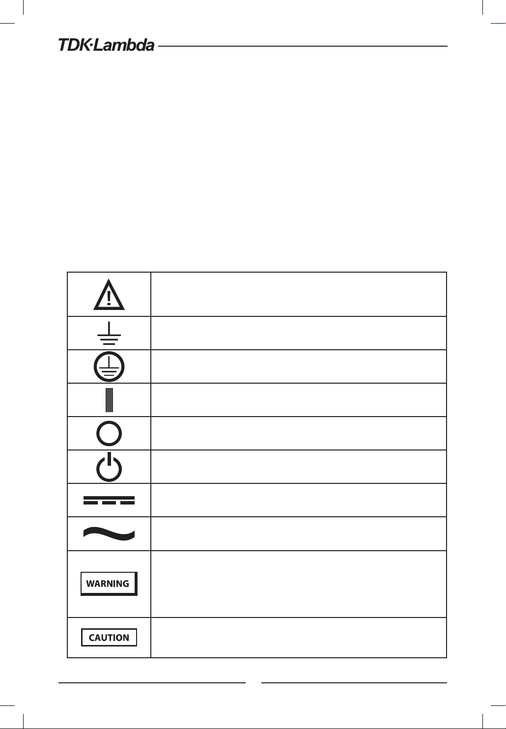
SYMBOLS
Caution, risk of danger. Instruction manual symbol. The instrument will be marked
with this symbol when it is necessary for the user to refer to the instruction manual.
Achtung Gefahr. Symbol im Benutzerhandbuch. Das Gerät wird mit diesem Symbol
gekennzeichnet, wenn der Benutzer Anweisungen im Handbuch beachten muss.
Indicates ground terminal.
Zeigt einen Erdungsanschluss an.
Protective Conductor Terminal.
Schutzleiterklemme.
ON (Supply).
EIN (Zufuhr).
OFF (Supply).
AUS (Zufuhr).
Standby (Supply) .
Standby (Zufuhr) .
Direct current (DC).
Gleichstrom (DC).
Alternate current (AC).
Wechselstrom (AC).
Denotes hazard. An attention to a procedure is called. Not following the procedure
correctly could result in personal injury. A WARNING sign should not be skipped and
all indicated conditions must be fully understood and met.
Bezeichnet Gefahren.Es wirddie Beachtung einesVerfahrens empfohlen. Nichteinhaltung
desVerfahrens kann zu Körperverletzung führen. EinWARN-Hinweis darf nicht ignoriert
und alle angeführten Verfahren müssen eindeutig verstanden und umgesetzt werden.
Denotes hazard. An attention to a procedure is called. Not following the procedure
correctly could result in damage to the equipment.
Bezeichnet Gefahren. Es wird die Beachtung einesVerfahrens empfohlen. Mangelhafte
Einhaltung des Verfahrens kann zu Beschädigung der Geräte führen.
WARNUNG:
Bei Einsatz einer Stromversorgung von über 60VDC Nennspannung besteht eine potentielle
Gesundheitsgefahr durch elektrischen Schlag. Schalten Sie keine Stromversorgung mit einer
Ausgangsspannung von über 60VDC EIN, ohne dass die Schutzabdeckungen der Ausgangsstecker und
Ausgangs-Stromschienen montiert sind. Schalten Sie die Stromversorgung AUS oder ziehen Sie den
Netzstecker, bevor Sie Anschlüsse auf der Rückseite vornehmen oder verändern.
WARNING:
There is a potential shock hazard when using a power supply with an output voltage greater than
60VDC. Do not turn ON power supply when output voltage is above 60VDC without output bus-bars
and output connectors protection assembled. Turn OFF power supply or disconnect power supply
from AC mains before making or changing any rear panel connection.

13
CHAPTER 1: GENERAL INFORMATION
1.1 User Manual Content
This user's manual contains the operating instructions, installation instructions and specifications
of the Z+Series 200W, 400W, 600W and 800W power supply series. The instructions refer to the
standard power supplies, including the built-in USB and RS232/485 serial communication. For
information related to operation with the optional LAN and IEEE, refer to User Manual for power
supply LAN and IEEE.
1.2 Introduction
1.2.1 General Description
Z+Series power supplies are wide output range, high performance switching power supplies.The
Z+Series is power factor corrected and operates from worldwide AC voltage range continuously.
Output voltage and current are continuously displayed and LED indicators show the complete
operating status of the power supply. The Front Panel controls allow the user to set the output
parameters, the protection levels (Over-Voltage protection, Under-Voltage protection and Foldback)
and preview the settings.The rear panel includes the necessary connectors to control and monitor
the power supply operation by remote analog signals or by the built-in serial communication USB
and RS232/485. LAN, IEEE and Isolated-Analog programming/monitoring are optional.
1.2.2 Models Covered by this Manual
Model Voltage range (V) Current range (A) Model Voltage range (V) Current range (A)
Z10-20 0-10 0-20 Z60-3.5 0-60 0-3.5
Z10-40 0-10 0-40 Z60-7 0-60 0-7
Z10-60 0-10 0-60 Z60-10 0-60 0-10
Z10-72 0-10 0-72 Z60-14 0-60 0-14
Z20-10 0-20 0-10 Z100-2 0-100 0-2
Z20-20 0-20 0-20 Z100-4 0-100 0-4
Z20-30 0-20 0-30 Z100-6 0-100 0-6
Z20-40 0-20 0-40 Z100-8 0-100 0-8
Z36-6 0-36 0-6
Z36-12 0-36 0-12
Z36-18 0-36 0-18
Z36-24 0-36 0-24
1.2.3 Features and Options
•Constant Voltage / Constant Current with automatic crossover.
•Active Power Factor correction.
•Universal Input Voltage 85-265Vac, continuous operation.
•Embedded Microprocessor Controller.
•Built in USB & RS232/485 Interface.
•Voltage & Current high resolution adjustment by digital Encoders.
•High resolution 16 bit ADCs & DACs.
•Software Calibration (no internal trimmers / potentiometers).
•Last Setting Memory.
•Independent Remote ON/OFF (Opto-Isolated) and Remote Enable/Disable.
•Parallel operation (Master/Slave) with Active current sharing.
•Remote sensing to compensate for voltage drop of power leads.
•External Analog Programming and Monitoring (0-5V or 0-10V, user selectable).
•Cooling fan speed control for low noise and extended fan life.
•Optional LAN interface (SCPI compatible).
•Optional IEEE interface (SCPI compatible).
•Optional Isolated Analog programming/monitoring (0-5V or 0-10V, user selectable and 4-20mA).

14
1.2.4 Multiple Output Power System
The Z+Series power supplies series can be configured into a programmable power system of up
to 31 units using the built-in USB or RS232/RS485 communication port in the power supply and
the RS485 linking cable provided with each power supply.
In a LAN system, each power supply can be controlled using the optional LAN controller (factory
installed). In an IEEE system, each power supply can be controlled using the optional IEEE controller
(factory installed).
1.2.5 Control via the USB or RS232/485 Communication Ports
The following parameters can be programmed via the serial communication port:
•Output voltage setting.
•Output current setting.
•Output voltage measurement.
•Output current measurement.
•Output on/off control.
•Foldback protection setting.
•Over-voltage protection setting and readback.
•Under-Voltage protection setting and readback.
•Under-Voltage limit setting and read back.
•Power-supply start up mode (last setting or safe mode).
1.2.6 Analog Voltage Programming and Monitoring
Analog inputs and outputs are provided at the rear panel for analog control of the power supply.
The output voltage and the current limit can be programmed by analog voltage or by resistor,
and can be monitored by analog voltage. The power supply output can be remotely set to On
or Off and analog signals monitor the proper operation of the power supply and the mode of
operation (CV/CC).
1.2.7 Parallel Operation
Up to six Z+Series power supplies of the same output voltage and current rating can be paralleled
in master-slave configuration with automatic current sharing to increase available power.
1.2.8 Output Connections
Output connections are made to rear panel bus-bars. Either the positive or negative terminal
may be grounded or the output may be floated.The power supplies shall not float outputs more
than +/- 100VDC above / below chassis ground. Contact factory for assistance with higher float
voltage applications.
Local or remote sense may be used. In remote sense, the voltage drop on the load wires should
be minimized. Refer to the specifications for the maximum voltage drop value.
1.2.9 Cooling and Mechanical Construction
The Z+Series is cooled by an internal fan. At installation, care must be taken to allow free air flow
into the power supply via the front panel, and out of the power supply via the rear panel. The Z+
Series power supply is a compact and lightweight unit which allows for easy installation and gives
a space saving solution for customer applications.

15
CAUTION:
Observe all torque guidelines within this manual. Over torque may damage unit or accessories.
Such damage is not covered under manufacturers warranty.
1.3 Accessories
1.3.1 General
Accessories are delivered with the power supply or separately upon ordering,The list below shows
the possible accessories and ordering numbers.
1.3.2 Serial Link Cable
Serial link cable, for linking power supplies by RS485 communication is provided with the power
supply.
Cable description: 0.5m length, shielded, RJ-45 type plugs, 8 contacts (P/N: GEN/RJ45).
1.3.3 Misc. Hardware
•Bus bars protection
•Connector protection
•Connector housing IPD1-06-D-K(SAMTEC)
•Connector housing IPD1-04-D-K(SAMTEC)
•Connector housing IPD1-02-D-K(SAMTEC)
•Contact pins P/N: CC79R-2024-01-L(SAMTEC)
1.3.4 AC Cables
AC cables are not provided with the power supply. If an AC cable is required, it should be ordered
according to the following:
Part no. Market Description
Z-U USA 13A 125V, non shielded, 2m typical length, with IEC60320-1, type C15
connector on one end and NEMA-5-15P type plug on the other end.
Z-E Europe 10A 250V, non shielded, 2m typical length, with IEC60320-1, type C15
connector on one end and IEC60884-1 type plug on the other end.
Z-J Japan 15A 125V, non shielded, 2m typical length, with IEC60320-1, type C15
connector on one end and Japan JIS C8303 type plug on the other end.
Z-C China 10A 250V, non shielded, 2m typical length, with IEC60320-1, type C15
connector on one end and China GB2099 or GB1002 type plug on the
other end.
Z-O GENERAL 10A 250V, non shielded, 2m typical length, with IEC60320-1, type C15
connector on one end and non-terminated stripped wires on the other
end. Use the cable only with plug approved by the national safety
standards of the country of usage.
Cable identification: LIVE: Brown ; NEUTRAL: Blue ; EARTH: Green/Yellow.
1.3.5 Serial Port Cables
If a serial port cable is required, it should be ordered according to the description in section 7.2
* USB cables are not provided with the power supply.
16
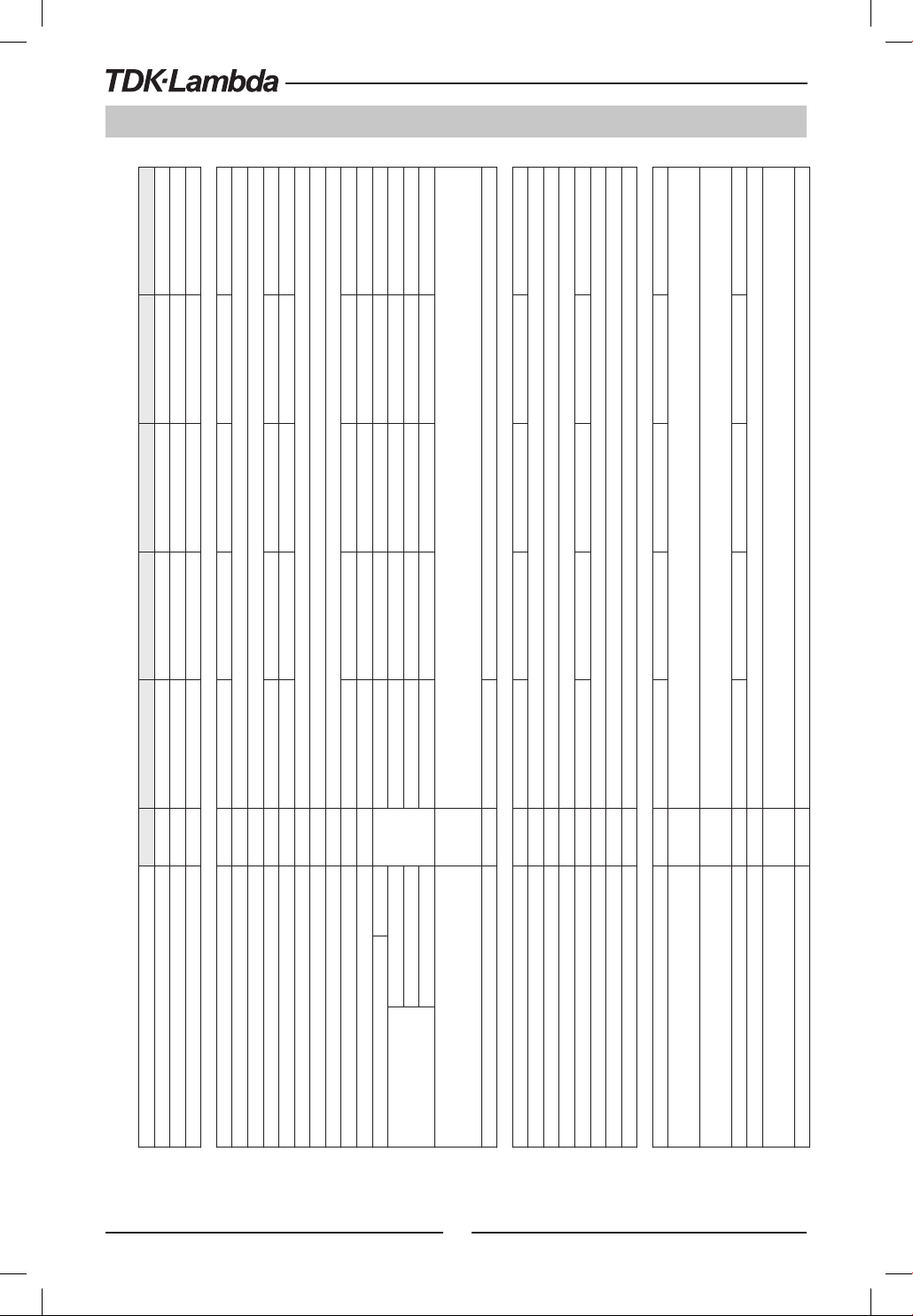
2.1 Z+
200 Series Specifications
MODEL Z 10-20 20-10 36-6 60-3.5 100-2
1. Rated output voltage(*1) V 10 20 36 60 100
2. Rated output current (*2) A 20 10 6 3.5 2
3. Rated output power W 200 200 216 210 200
CONSTANT VOLTAGE MODE Z 10-20 20-10 36-6 60-3.5 100-2
1. Max. Line regulation (*6) --- 0.01% of rated output voltage+2mV
2. Max. Load regulation (*7) --- 0.01% of rated output voltage+2mV
3. Ripple and noise (p-p, 20MHz) (*8) mV 50 50 50 50 80
4. Ripple r.m.s. 5Hz~1MHz mV 5 6 6 7 8
5. Temperature coefficient PPM/°C 30PPM/°C from rated output voltage, following 30 minutes warm-up.
6. Temperature stability --- 0.02% of rated Vout over 8hrs. interval following 30 minutes warm-up. Constant line, load & temp.
7. Warm-up drift --- Less than 0.05% of rated output voltage+2mV over 30 minutes following power on.
8. Remote sense compensation/wire V 1 1 2 3 5
9. Up-prog. Response time, 0~Vomax.(*9) mS 15 30 30 50 50
10. Down-prog. response time:
Full load (*9)
mS
12 25 30 40 50
Time delay (*17) 210 250 320 380 1200
No load (*10) (*15)(*17) 40 65 85 100 250
No load (*10) (*16)(*17) 200 200 290 310 1100
11. Transient response time mS
Time for output voltage to recover within 0.5% of its rated output for a load change 10~90% of rated output current.
Output set-point: 10~100%, Local sense
Less than 1mS, for models up to and including 100V
12. Hold-up time (*19) --- 15mSec Typical. 16mSec Typical.
CONSTANT CURRENT MODE Z 10-20 20-10 36-6 60-3.5 100-2
1. Max. Line regulation (*6) --- 0.01% of rated output current+2mA
2. Max. Load regulation (*11) --- 0.01% of rated output current+5mA
3. Load regulation thermal drift --- Less than 0.05% of rated output current over 30 minutes following load change.
4. Ripple r.m.s. 5Hz~1MHz (*12) mA 25 15 8 4 3
5. Temperature coefficient PPM/°C 100PPM/°C from rated output current, following 30 minutes warm-up.
6. Temperature stability --- 0.05% of rated Iout over 8hrs. interval following 30 minutes warm-up. Constant line, load & temperature.
7. Warm-up drift --- Less than +/-0.1% of rated output current over 30 minutes following power on.
PROTECTIVE FUNCTIONS Z 10-20 20-10 36-6 60-3.5 100-2
1. Foldback protection --- Output shut-down when power supply change mode from CV to CC or CC to CV. User presetable.
Reset by AC input recycle in autostart mode or by OUTPUT button or by rear panel ENABLE, or by communication port.
2. Over-voltage protection (OVP) --- Inverter Shut down method. Reset by AC input recycle in autostart mode or by OUTPUT button or by rear panel ENABLE, or by
communication port.
3. Over -voltage trip point V 0.5~12 1~24 2~40 5~66 5~110
4. Output under voltage limit (UVL) --- Preset by front panel or communication port. Prevents from adjusting Vout below limit. Does not affect in analog programming.
5. Output under voltage protection (UVP) --- Output shut-down when power supply output voltage goes below UVP programming. User presetable.
Reset by AC input recycle in autostart mode or by OUTPUT button or by rear panel ENABLE, or by communication port.
6. Over temperature protection --- User selectable, latched or non latched.
ANALOG PROGRAMMING AND MONITORING
1. Vout voltage programming --- 0~100%, 0~5V or 0~10V, user selectable. Accuracy and linearity: +/-0.5% of rated Vout.
2. Iout voltage programming (*13) --- 0~100%, 0~5V or 0~10V, user selectable. Accuracy and linearity: +/-1% of rated Iout.
3. Vout resistor programming --- 0~100%, 0~5/10Kohm full scale, user selectable. Accuracy and linearity: +/-1% of rated Vout.
4. Iout resistor programming (*13) --- 0~100%, 0~5/10Kohm full scale, user selectable. Accuracy and linearity: +/-1.5% of rated Iout.
5. Shut Off (SO) control --- By electrical Voltage: 0~0.6V/4~15V or dry contact, user selectable logic.
6. Output current monitor (*13) --- 0~5V or 0~10V, user selectable. Accuracy: +/-1%.
7. Output voltage monitor --- 0~5V or 0~10V, user selectable. Accuracy: +/-1%.
8. Power supply OK signal --- 4~5V-OK, 0V-Fail. 500ohm series resistance.
9. Parallel operation (*20) --- Possible, up to 6 units in master/slave mode with single wire current balance connection.
10. Series operation --- 2 identical units (with external diodes).
11. CV/CC indicator --- Open collector. CC mode: On, CV mode: Off. Maximum voltage: 30V, maximum sink current: 10mA
12. Interlock (ILC) control ---
Enables/Disables the PS output by dry contact (Short: On, Open: Off, Source current: less than 0.5mA). Ena/Dis is activated by front panel.
13. Local/Remote mode Control --- By electrical signal or Open/Short: 0~0.6V or short: Remote, 2~15V or open: Local
14. Local/Remote mode Indicator --- Open collector (shunted by 36V zener). On (0~0.6V, 10mA sink current max.)-Remote. Off-Local (30V max.).
15.Trigger out --- Maximum low level output =0.8V, Minimum high level output =3.8V, Maximum high level output =5V,
Maximum source current =16mA, pulse =20μs Typical.
16.Trigger in --- Maximum low level input =1.2V, Minimum high level input =3.5V, Maximum high level input =5V, Maximum sink current =16mA,
positive edge, trigger: tw =10μs minimum, Tr/Tf =1μs maximum.
17. Programmed signal 1 --- Open collector, maximum voltage 25V,maximum sink current 100mA. (Shunted by 27V zener)
18. Programmed signal 2 --- Open collector, maximum voltage 25V,maximum sink current 100mA. (Shunted by 27V zener)
FRONT PANEL
1. Control functions
--- Multiple options with 2 Encoders
--- Vout/Iout manual adjust
--- OVP/UVL/UVP manual adjust
--- Protection Functions - OVP, UVL,UVP, Foldback, OCP, INT, SO
--- Communication Functions - Selection of LAN,IEEE,RS232,RS485,USB
--- Communication Functions - Selection of Baud Rate, Address
--- Analog Control Functions - Selection Voltage/resistive programming, 5V/10V, 5K/10K programming
--- Analog Control Functions - Selection of Voltage/Current Monitoring 5V/10V, Output ON/OFF, Front Panel Lock.
2. Display --- Vout: 4 digits, accuracy: 0.5% of rated output voltage+/-1 count.
--- Iout: 4 digits, accuracy: 0.5% of rated output current+/-1 count.
3. Indications --- GREEN LEDs: FINE, MENU, PREV, PROT, REM, OUTPUT, CV, CC
--- RED LED: PROT (OVP, UVP, OTP, FOLD, AC FAIL).
4. Function buttons
--- FINE, MENU, PREV, PROT, REM, OUTPUT
PROGRAMMING AND READBACK (RS232/485,USB, Optional: IEEE, LAN)
1. Vout programming accuracy --- 0.05% of rated output voltage
2. Iout programming accuracy (*13) --- 0.1% of actual +0.1% of rated output current
3. Vout programming resolution --- 0.012% of full scale
4. Iout programming resolution --- 0.012% of full scale
5. Vout readback accuracy --- 0.05% of rated output voltage
6. Iout readback accuracy (*13) --- 0.1% of actual +0.3% of rated output current
7. Vout readback resolution --- 0.012% of full scale
8. Iout readback resolution --- 0.012% of full scale
CHAPTER 2: SPECIFICATIONS

17
2.1 Z+200 Series Specifications
MODEL Z 10-20 20-10 36-6 60-3.5 100-2
1. Rated output voltage(*1) V 10 20 36 60 100
2. Rated output current (*2) A 20 10 6 3.5 2
3. Rated output power W 200 200 216 210 200
CONSTANT VOLTAGE MODE Z 10-20 20-10 36-6 60-3.5 100-2
1. Max. Line regulation (*6) --- 0.01% of rated output voltage+2mV
2. Max. Load regulation (*7) --- 0.01% of rated output voltage+2mV
3. Ripple and noise (p-p, 20MHz) (*8) mV 50 50 50 50 80
4. Ripple r.m.s. 5Hz~1MHz mV 5 6 6 7 8
5. Temperature coefficient PPM/°C 30PPM/°C from rated output voltage, following 30 minutes warm-up.
6. Temperature stability --- 0.02% of rated Vout over 8hrs. interval following 30 minutes warm-up. Constant line, load & temp.
7. Warm-up drift --- Less than 0.05% of rated output voltage+2mV over 30 minutes following power on.
8. Remote sense compensation/wire V 1 1 2 3 5
9. Up-prog. Response time, 0~Vomax.(*9) mS 15 30 30 50 50
10. Down-prog. response time:
Full load (*9)
mS
12 25 30 40 50
Time delay (*17) 210 250 320 380 1200
No load (*10) (*15)(*17) 40 65 85 100 250
No load (*10) (*16)(*17) 200 200 290 310 1100
11. Transient response time mS
Time for output voltage to recover within 0.5% of its rated output for a load change 10~90% of rated output current.
Output set-point: 10~100%, Local sense
Less than 1mS, for models up to and including 100V
12. Hold-up time (*19) --- 15mSec Typical. 16mSec Typical.
CONSTANT CURRENT MODE Z 10-20 20-10 36-6 60-3.5 100-2
1. Max. Line regulation (*6) --- 0.01% of rated output current+2mA
2. Max. Load regulation (*11) --- 0.01% of rated output current+5mA
3. Load regulation thermal drift --- Less than 0.05% of rated output current over 30 minutes following load change.
4. Ripple r.m.s. 5Hz~1MHz (*12) mA 25 15 8 4 3
5. Temperature coefficient PPM/°C 100PPM/°C from rated output current, following 30 minutes warm-up.
6. Temperature stability --- 0.05% of rated Iout over 8hrs. interval following 30 minutes warm-up. Constant line, load & temperature.
7. Warm-up drift --- Less than +/-0.1% of rated output current over 30 minutes following power on.
PROTECTIVE FUNCTIONS Z 10-20 20-10 36-6 60-3.5 100-2
1. Foldback protection --- Output shut-down when power supply change mode from CV to CC or CC to CV. User presetable.
Reset by AC input recycle in autostart mode or by OUTPUT button or by rear panel ENABLE, or by communication port.
2. Over-voltage protection (OVP) --- Inverter Shut down method. Reset by AC input recycle in autostart mode or by OUTPUT button or by rear panel ENABLE, or by
communication port.
3. Over -voltage trip point V 0.5~12 1~24 2~40 5~66 5~110
4. Output under voltage limit (UVL) --- Preset by front panel or communication port. Prevents from adjusting Vout below limit. Does not affect in analog programming.
5. Output under voltage protection (UVP) --- Output shut-down when power supply output voltage goes below UVP programming. User presetable.
Reset by AC input recycle in autostart mode or by OUTPUT button or by rear panel ENABLE, or by communication port.
6. Over temperature protection --- User selectable, latched or non latched.
ANALOG PROGRAMMING AND MONITORING
1. Vout voltage programming --- 0~100%, 0~5V or 0~10V, user selectable. Accuracy and linearity: +/-0.5% of rated Vout.
2. Iout voltage programming (*13) --- 0~100%, 0~5V or 0~10V, user selectable. Accuracy and linearity: +/-1% of rated Iout.
3. Vout resistor programming --- 0~100%, 0~5/10Kohm full scale, user selectable. Accuracy and linearity: +/-1% of rated Vout.
4. Iout resistor programming (*13) --- 0~100%, 0~5/10Kohm full scale, user selectable. Accuracy and linearity: +/-1.5% of rated Iout.
5. Shut Off (SO) control --- By electrical Voltage: 0~0.6V/4~15V or dry contact, user selectable logic.
6. Output current monitor (*13) --- 0~5V or 0~10V, user selectable. Accuracy: +/-1%.
7. Output voltage monitor --- 0~5V or 0~10V, user selectable. Accuracy: +/-1%.
8. Power supply OK signal --- 4~5V-OK, 0V-Fail. 500ohm series resistance.
9. Parallel operation (*20) --- Possible, up to 6 units in master/slave mode with single wire current balance connection.
10. Series operation --- 2 identical units (with external diodes).
11. CV/CC indicator --- Open collector. CC mode: On, CV mode: Off. Maximum voltage: 30V, maximum sink current: 10mA
12. Interlock (ILC) control ---
Enables/Disables the PS output by dry contact (Short: On, Open: Off, Source current: less than 0.5mA). Ena/Dis is activated by front panel.
13. Local/Remote mode Control --- By electrical signal or Open/Short: 0~0.6V or short: Remote, 2~15V or open: Local
14. Local/Remote mode Indicator --- Open collector (shunted by 36V zener). On (0~0.6V, 10mA sink current max.)-Remote. Off-Local (30V max.).
15.Trigger out --- Maximum low level output =0.8V, Minimum high level output =3.8V, Maximum high level output =5V,
Maximum source current =16mA, pulse =20μs Typical.
16.Trigger in --- Maximum low level input =1.2V, Minimum high level input =3.5V, Maximum high level input =5V, Maximum sink current =16mA,
positive edge, trigger: tw =10μs minimum, Tr/Tf =1μs maximum.
17. Programmed signal 1 --- Open collector, maximum voltage 25V,maximum sink current 100mA. (Shunted by 27V zener)
18. Programmed signal 2 --- Open collector, maximum voltage 25V,maximum sink current 100mA. (Shunted by 27V zener)
FRONT PANEL
1. Control functions
--- Multiple options with 2 Encoders
--- Vout/Iout manual adjust
--- OVP/UVL/UVP manual adjust
--- Protection Functions - OVP, UVL,UVP, Foldback, OCP, INT, SO
--- Communication Functions - Selection of LAN,IEEE,RS232,RS485,USB
--- Communication Functions - Selection of Baud Rate, Address
--- Analog Control Functions - Selection Voltage/resistive programming, 5V/10V, 5K/10K programming
--- Analog Control Functions - Selection of Voltage/Current Monitoring 5V/10V, Output ON/OFF, Front Panel Lock.
2. Display --- Vout: 4 digits, accuracy: 0.5% of rated output voltage+/-1 count.
--- Iout: 4 digits, accuracy: 0.5% of rated output current+/-1 count.
3. Indications --- GREEN LEDs: FINE, MENU, PREV, PROT, REM, OUTPUT, CV, CC
--- RED LED: PROT (OVP, UVP, OTP, FOLD, AC FAIL).
4. Function buttons
--- FINE, MENU, PREV, PROT, REM, OUTPUT
PROGRAMMING AND READBACK (RS232/485,USB, Optional: IEEE, LAN)
1. Vout programming accuracy --- 0.05% of rated output voltage
2. Iout programming accuracy (*13) --- 0.1% of actual +0.1% of rated output current
3. Vout programming resolution --- 0.012% of full scale
4. Iout programming resolution --- 0.012% of full scale
5. Vout readback accuracy --- 0.05% of rated output voltage
6. Iout readback accuracy (*13) --- 0.1% of actual +0.3% of rated output current
7. Vout readback resolution --- 0.012% of full scale
8. Iout readback resolution --- 0.012% of full scale
18
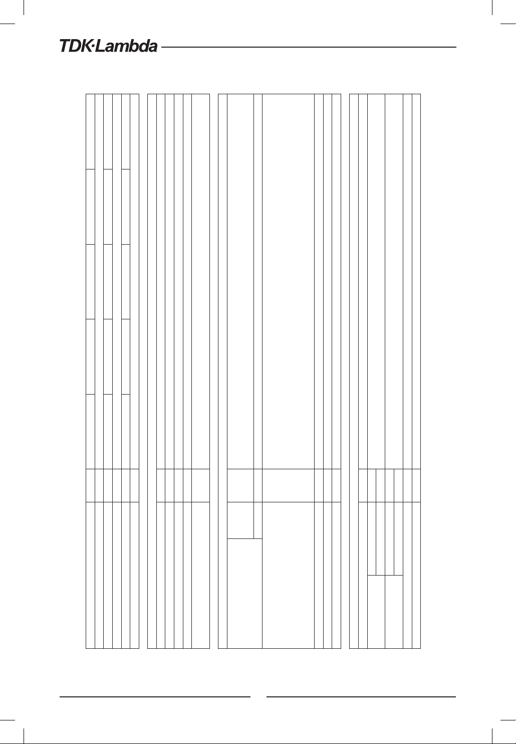
Z+200 Series Specifications
INPUT CHARACTERISTICS Z 10-20 20-10 36-6 60-3.5 100-2
1. Input voltage/freq. (*3) --- 85~265Vac continuous, 47~63Hz, single phase
2. Maximum Input current 100/200VAC (*4) (*18) --- 2.65/1.31 2.62/1.29 2.76/1.37 2.69/1.33 2.55/1.26
3. Power Factor (Typ) --- >0.99 at 100Vac, >0.98 at 200Vac,100% load
4. Efficiency (Typ) 100/200VAC (*4) (*18) % 76/77.5 77/79 79/80.5 79/80.5 79/81
5. Inrush current 100/200VAC (*5) --- Less than 15A/30A
ENVIRONMENTAL CONDITIONS
1. Operating temperature --- 0~50°C, 100% load.
2. Storage temperature --- -20~85°C
3. Operating humidity % 20~90% RH (no condensation).
4. Storage humidity % 10~95% RH (no condensation).
5. Altitude --- Maximum 3000m. Derate ambient temp above 2000m.
Operating: Maximum ambient temperature, From 2000m up to 3000m Ambient temperature 40°C.
SAFETY/EMC
1. Applicable standards: Safety ---
UL61010-1, EN61010-1, IEC61010-1. Design to meet UL60950-1, EN60950-1
10V≤Vout≤60V: Output,J1,J2,J3,J4,USB,LAN,IEEE/ISOLATED Analog are Non Hazardous
Vout=100V:Output,J1,J2 are Hazardous J3,J4,USB, IEEE/ISOLATED Analog ,LAN are Non Hazardous
EMC --- IEC/EN61326-1 (Built to meet EN55022/EN55024)
2. Withstand voltage ---
10≤Vout≤36V models: Input-Output&J1,J2,J3,J4,USB,LAN/IEEE/ISOLATED ANALOG: 4242VDC/1min; Input-Ground: 2828VDC/1min.
Output&J1,J2,J3,J4,USB,LAN/IEEE/ISOLATED ANALOG-Ground: 707VDC/1min.
60V,100V models: Input-Output&J1,J2: 4242VDC/1min; Input-J3,J4,USB,LAN/IEEE/ISOLATED Analog: 4242VDC/1min; Input-Ground:
2828VDC/1min.
Output&J1,J2- J3,J4,USB,LAN/IEEE/ISOLATED ANALOG :1910VDC/1min; Output&J1,J2-Ground: 1380VDC/1min.
J3, J4, USB/LAN/IEEE/ISOLATED ANALOG - Ground: 707VDC/1min;
3. Insulation resistance --- More than 100Mohm at 25°C, 70%RH.
4. Conducted emission --- IEC/EN61326-1 Industrial Location - B, FCC part 15-B, VCCI-B
5. Radiated emission --- IEC/EN61326-1 Industrial Location - A, FCC part 15-A, VCCI-A
MECHANICAL
1. Cooling --- Forced air cooling by internal fan.
2. Weight STANDARD Kg Less than 1.9Kg.
Less than 2.4Kg. Wide body with Isolated analog or Binding post or IEEE.
WIDE BODY Kg
3. Dimensions (WxHxD) STANDARD mm H: 83, W: 70, D: 350 (excluding bus bars, handles…). (Refer to Outline drawing).
H: 83, W: 105, D: 350 (excluding bus bars, handles…). (Refer to Outline drawing).
WIDE BODY mm
4. Vibration --- According to: IEC60068-2-64
5. Shock --- Less than 20G, half sine, 11mS. Unit is unpacked. According to: IEC60068-2-27
NOTES:
*1: Minimum voltage is guaranteed to maximum 0.1% of rated output voltage.
*2: Minimum current is guaranteed to maximum 0.2% of rated output current.
*3: For cases where conformance to various safety standards (UL, IEC, etc…) is required, to be described as 100-240Vac (50/60Hz).
*4: Ta=25°C with rated output power.
*5: Not including EMI filter inrush current, less than 0.2mSec at cold start Ta=25°C
*6: At 85~132Vac or 170~265VAC, constant load.
*7: From No-Load to Full-Load, constant input voltage. Measured at the sensing point in Remote Sense.
*8: Measured with JEITA RC-9131A (1:1) probe.
*9: From 10% to 90% or 90% to 10% of Rated Output Voltage, with rated resistive load.
*10: From 90% to 10% of Rated Output Voltage.
*11: For load voltage change, equal to the unit voltage rating, constant input voltage.
*12: For 10V model the ripple is measured at 2V to rated output voltage and rated output current. For other models, the ripple is measured at 10~100%
of rated output voltage and rated output current.
*13: The Constant Current programming, readback and monitoring accuracy do not include the warm-up and Load regulation thermal drift.
*14: Measured with JEITA RC-9131A (1:1) probe.
*15: For cases where the time interval between each down programming is longer than Td (time delay).
*16: For cases where the time interval between each down programming is shorter than Td (time delay).
*17: Td typical Minimum time between consecutive down programming cycles.
*18: PS with Lan, IEEE, models decrease efficiency by 0.5% and increase input current by 0.5%.
PS with Isolated analog option decreases efficiency by 1.5% and increases input current by 1.5%.
*19: At rated output power.
*20: For Parallel operation more than 2 units 5% of total output current is requierd.

19
Z+200 Series Specifications
INPUT CHARACTERISTICS Z 10-20 20-10 36-6 60-3.5 100-2
1. Input voltage/freq. (*3) --- 85~265Vac continuous, 47~63Hz, single phase
2. Maximum Input current 100/200VAC (*4) (*18) --- 2.65/1.31 2.62/1.29 2.76/1.37 2.69/1.33 2.55/1.26
3. Power Factor (Typ) --- >0.99 at 100Vac, >0.98 at 200Vac,100% load
4. Efficiency (Typ) 100/200VAC (*4) (*18) % 76/77.5 77/79 79/80.5 79/80.5 79/81
5. Inrush current 100/200VAC (*5) --- Less than 15A/30A
ENVIRONMENTAL CONDITIONS
1. Operating temperature --- 0~50°C, 100% load.
2. Storage temperature --- -20~85°C
3. Operating humidity % 20~90% RH (no condensation).
4. Storage humidity % 10~95% RH (no condensation).
5. Altitude --- Maximum 3000m. Derate ambient temp above 2000m.
Operating: Maximum ambient temperature, From 2000m up to 3000m Ambient temperature 40°C.
SAFETY/EMC
1. Applicable standards: Safety ---
UL61010-1, EN61010-1, IEC61010-1. Design to meet UL60950-1, EN60950-1
10V≤Vout≤60V: Output,J1,J2,J3,J4,USB,LAN,IEEE/ISOLATED Analog are Non Hazardous
Vout=100V:Output,J1,J2 are Hazardous J3,J4,USB, IEEE/ISOLATED Analog ,LAN are Non Hazardous
EMC --- IEC/EN61326-1 (Built to meet EN55022/EN55024)
2. Withstand voltage ---
10≤Vout≤36V models: Input-Output&J1,J2,J3,J4,USB,LAN/IEEE/ISOLATED ANALOG: 4242VDC/1min; Input-Ground: 2828VDC/1min.
Output&J1,J2,J3,J4,USB,LAN/IEEE/ISOLATED ANALOG-Ground: 707VDC/1min.
60V,100V models: Input-Output&J1,J2: 4242VDC/1min; Input-J3,J4,USB,LAN/IEEE/ISOLATED Analog: 4242VDC/1min; Input-Ground:
2828VDC/1min.
Output&J1,J2- J3,J4,USB,LAN/IEEE/ISOLATED ANALOG :1910VDC/1min; Output&J1,J2-Ground: 1380VDC/1min.
J3, J4, USB/LAN/IEEE/ISOLATED ANALOG - Ground: 707VDC/1min;
3. Insulation resistance --- More than 100Mohm at 25°C, 70%RH.
4. Conducted emission --- IEC/EN61326-1 Industrial Location - B, FCC part 15-B, VCCI-B
5. Radiated emission --- IEC/EN61326-1 Industrial Location - A, FCC part 15-A, VCCI-A
MECHANICAL
1. Cooling --- Forced air cooling by internal fan.
2. Weight STANDARD Kg Less than 1.9Kg.
Less than 2.4Kg. Wide body with Isolated analog or Binding post or IEEE.
WIDE BODY Kg
3. Dimensions (WxHxD) STANDARD mm H: 83, W: 70, D: 350 (excluding bus bars, handles…). (Refer to Outline drawing).
H: 83, W: 105, D: 350 (excluding bus bars, handles…). (Refer to Outline drawing).
WIDE BODY mm
4. Vibration --- According to: IEC60068-2-64
5. Shock --- Less than 20G, half sine, 11mS. Unit is unpacked. According to: IEC60068-2-27
NOTES:
*1: Minimum voltage is guaranteed to maximum 0.1% of rated output voltage.
*2: Minimum current is guaranteed to maximum 0.2% of rated output current.
*3: For cases where conformance to various safety standards (UL, IEC, etc…) is required, to be described as 100-240Vac (50/60Hz).
*4: Ta=25°C with rated output power.
*5: Not including EMI filter inrush current, less than 0.2mSec at cold start Ta=25°C
*6: At 85~132Vac or 170~265VAC, constant load.
*7: From No-Load to Full-Load, constant input voltage. Measured at the sensing point in Remote Sense.
*8: Measured with JEITA RC-9131A (1:1) probe.
*9: From 10% to 90% or 90% to 10% of Rated Output Voltage, with rated resistive load.
*10: From 90% to 10% of Rated Output Voltage.
*11: For load voltage change, equal to the unit voltage rating, constant input voltage.
*12: For 10V model the ripple is measured at 2V to rated output voltage and rated output current. For other models, the ripple is measured at 10~100%
of rated output voltage and rated output current.
*13: The Constant Current programming, readback and monitoring accuracy do not include the warm-up and Load regulation thermal drift.
*14: Measured with JEITA RC-9131A (1:1) probe.
*15: For cases where the time interval between each down programming is longer than Td (time delay).
*16: For cases where the time interval between each down programming is shorter than Td (time delay).
*17: Td typical Minimum time between consecutive down programming cycles.
*18: PS with Lan, IEEE, models decrease efficiency by 0.5% and increase input current by 0.5%.
PS with Isolated analog option decreases efficiency by 1.5% and increases input current by 1.5%.
*19: At rated output power.
*20: For Parallel operation more than 2 units 5% of total output current is requierd.
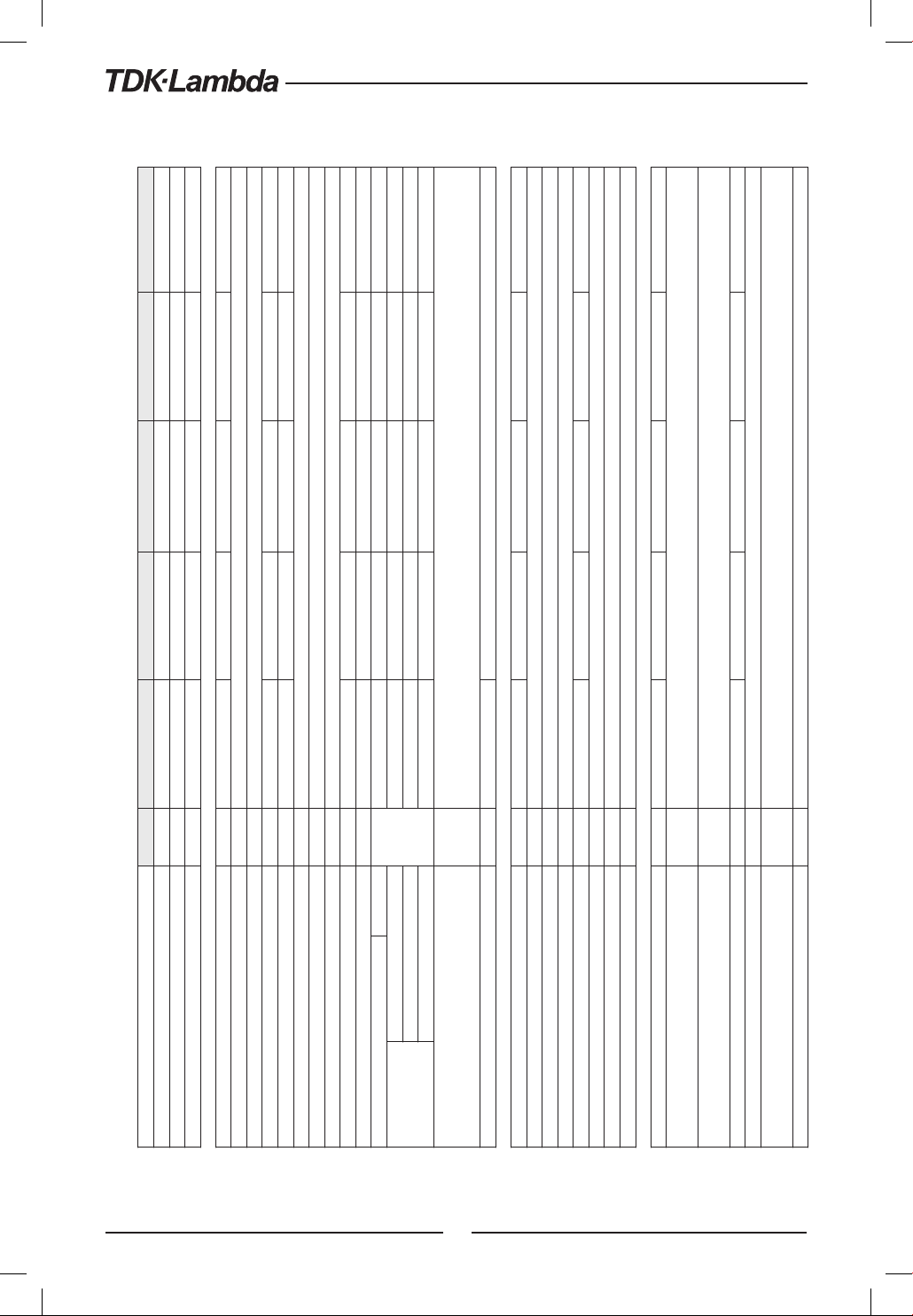
20
2.2 Z+
400 Series Specifications
MODEL Z 10-40 20-20 36-12 60-7 100-4
1. Rated output voltage(*1) V 10 20 36 60 100
2. Rated output current (*2) A 40 20 12 7 4
3. Rated output power W 400 400 432 420 400
CONSTANT VOLTAGE MODE Z 10-40 20-20 36-12 60-7 100-4
1. Max. Line regulation (*6) --- 0.01% of rated output voltage+2mV
2. Max. Load regulation (*7) --- 0.01% of rated output voltage+2mV
3. Ripple and noise (p-p, 20MHz) (*8) mV 50 50 50 50 80
4. Ripple r.m.s. 5Hz~1MHz mV 5 6 6 7 8
5. Temperature coefficient PPM/°C 30PPM/°C from rated output voltage, following 30 minutes warm-up.
6. Temperature stability --- 0.02% of rated Vout over 8hrs. interval following 30 minutes warm-up. Constant line, load & temp.
7. Warm-up drift --- Less than 0.05% of rated output voltage+2mV over 30 minutes following power on.
8. Remote sense compensation/wire V 1 1 2 3 5
9. Up-prog. Response time, 0~Vomax.(*9) mS 15 30 30 50 50
10. Down-prog. response time: Full load (*9)
mS
10 10 15 30 50
Time delay (*17) 210 250 320 380 1200
No load (*10) (*15) (*17) 40 65 85 100 250
No load (*10) (*16) (*17) 200 200 290 310 1100
11. Transient response time mS
Time for output voltage to recover within 0.5% of its rated output for a load change 10~90% of rated output current.
Output set-point: 10~100%, Local sense.
Less than 1mS, for models up to and including 100V
12. Hold-up time (*19) --- 15mSec Typical. 16mSec Typical.
CONSTANT CURRENT MODE Z 10-40 20-20 36-12 60-7 100-4
1. Max. Line regulation (*6) --- 0.01% of rated output current+2mA
2. Max. Load regulation (*11) --- 0.01% of rated output current+5mA
3. Load regulation thermal drift --- Less than 0.05% of rated output current over 30 minutes following load change.
4. Ripple r.m.s. 5Hz~1MHz (*12) mA 70 40 15 8 3
5. Temperature coefficient PPM/°C 100PPM/°C from rated output current, following 30 minutes warm-up.
6. Temperature stability --- 0.05% of rated Iout over 8hrs. interval following 30 minutes warm-up. Constant line, load & temperature.
7. Warm-up drift --- Less than +/-0.1% of rated output current over 30 minutes following power on.
PROTECTIVE FUNCTIONS Z 10-40 20-20 36-12 60-7 100-4
1. Foldback protection --- Output shut-down when power supply change mode from CV to CC or CC to CV. User presetable.
Reset by AC input recycle in autostart mode or by OUTPUT button or by rear panel ENABLE, or by communication port.
2. Over-voltage protection (OVP) --- Inverter Shut down method. Reset by AC input recycle in autostart mode or by OUTPUT button or by rear panel ENABLE,
or by communication port.
3. Over - voltage trip point V 0.5~12 1~24 2~40 5~66 5~110
4. Output under voltage limit (UVL) --- Preset by front panel or communication port. Prevents from adjusting Vout below limit. Does not affect in analog programming.
5. Output under voltage protection (UVP) --- Output shut-down when power supply output voltage goes below UVP programming. User presetable.
Reset by AC input recycle in autostart mode or by OUTPUT button or by rear panel ENABLE, or by communication port.
6. Over temperature protection --- User Selectable. Latched or non latched
ANALOG PROGRAMMING AND MONITORING
1. Vout voltage programming --- 0~100%, 0~5V or 0~10V, user selectable. Accuracy and linearity: +/-0.5% of rated Vout.
2. Iout voltage programming (*13) --- 0~100%, 0~5V or 0~10V, user selectable. Accuracy and linearity: +/-1% of rated Iout.
3. Vout resistor programming --- 0~100%, 0~5/10Kohm full scale, user selectable. Accuracy and linearity: +/-1% of rated Vout.
4. Iout resistor programming (*13) --- 0~100%, 0~5/10Kohm full scale, user selectable. Accuracy and linearity: +/-1.5% of rated Iout.
5. Shut Off (SO) control --- By electrical Voltage: 0~0.6V/4~15V or dry contact, user selectable logic.
6. Output current monitor (*13) --- 0~5V or 0~10V, user selectable. Accuracy: +/-1%.
7. Output voltage monitor --- 0~5V or 0~10V, user selectable. Accuracy: +/-1%.
8. Power supply OK signal --- 4~5V-OK, 0V-Fail. 500ohm series resistance.
9. Parallel operation (*21) --- Possible, up to 6 units in master/slave mode with single wire current balance connection.
10. Series operation --- 2 identical units (with external diodes).
11. CV/CC indicator --- Open collector. CC mode: On, CV mode: Off. Maximum voltage: 30V, maximum sink current: 10mA
12. Interlock (ILC) control ---
Enables/Disables the PS output by dry contact (Short: On, Open: Off, Source current: less than 0.5mA). Ena/Dis is activated by front panel.
13. Local/Remote mode Control --- By electrical signal or Open/Short: 0~0.6V or short: Remote, 2~15V or open: Local
14. Local/Remote mode Indicator --- Open collector (shunted by 36V zener). On (0~0.6V, 10mA sink current max.)-Remote. Off-Local (30V max.).
15.Trigger out --- Maximum low level output =0.8V, Minimum high level output =3.8V, Maximum high level output =5V,
Maximum source current =16mA, pulse =20μs Typical.
16.Trigger in --- Maximum low level input =1.2V, Minimum high level input =3.5V, Maximum high level input =5V, Maximum sink current =16mA,
positive edge, trigger: tw =10μs minimum, Tr/Tf =1μs maximum.
17. Programmed signal 1 --- Open collector, maximum voltage 25V, maximum sink current 100mA. (Shunted by 27V zener)
18. Programmed signal 2 --- Open collector, maximum voltage 25V, maximum sink current 100mA. (Shunted by 27V zener)
FRONT PANEL
1. Control functions
--- Multiple options with 2 Encoders
--- Vout/Iout manual adjust
--- OVP/UVL /UVP manual adjust
--- Protection Functions - OVP, UVL, UVP, Foldback, OCP, INT, SO
--- Communication Functions - Selection of LAN,IEEE (*20), RS232,RS485,USB
--- Communication Functions - Selection of Baud Rate, Address
--- Analog Control Functions - Selection Voltage/resistive programming, 5V/10V, 5K/10K programming
--- Analog Control Functions - Selection of Voltage/Current Monitoring 5V/10V, Output ON/OFF, Front Panel Lock.
2. Display --- Vout: 4 digits, accuracy: 0.5% of rated output voltage+/-1 count.
--- Iout: 4 digits, accuracy: 0.5% of rated output current+/-1 count.
3. Indications --- GREEN LEDs: FINE, MENU, PREV, PROT, REM, OUTPUT, CV, CC
--- RED LED: PROT (OVP, UVP, OTP, FOLD, AC FAIL).
4. Function buttons --- FINE, MENU, PREV, PROT, REM, OUTPUT
PROGRAMMING AND READBACK (RS232/485,USB, Optional: IEEE(*20), LAN)
1. Vout programming accuracy --- 0.05% of rated output voltage
2. Iout programming accuracy (*13) --- 0.1% of actual +0.1% of rated output current
3. Vout programming resolution --- 0.012% of full scale
4. Iout programming resolution --- 0.012% of full scale
5. Vout readback accuracy --- 0.05% of rated output voltage
6. Iout readback accuracy (*13) --- 0.1% of actual +0.3% of rated output current
7. Vout readback resolution --- 0.012% of full scale
8. Iout readback resolution --- 0.012% of full scale
This manual suits for next models
19
Table of contents
Other TDK-Lambada Power Supply manuals

Popular Power Supply manuals by other brands


Caen
Caen A1539 quick start guide

Coolmax
Coolmax CP-500T user guide

Enerdrive
Enerdrive Wanderer installation guide

Hydromatic
Hydromatic A+ Installation and service manual

Daintree
Daintree GE Tetra GEPS12-180U-NA installation guide

Lutron Electronics
Lutron Electronics QSPS-P1-1-50 installation instructions


