TDK-Lambada HWS?HWS User manual

HWSSeries
AC-DCSwitchingPowerSupply
HWS・HWS/ME・HWS/HD・HWS-P
Environmental-friendly
User-friendly
Safety
●Green power line
●Complies with RoHS Directive
●Energy Saving
●Miniature package
●Unified style
●Extensive product line
●High reliability design
●Safety-oriented design
●Safe to operate
HWS Series Line Up
■HWS Series Model Name
HWS *** - ** **
Output power
Output voltage
Option code
● Output power
In addition to 11 models for 15W 〜1800W, there are 2 models
for peak power models which bring the total of 13 models.
● Output voltage
Wide variety of line up from 3.3V to 48V. 60V is also available for 1000W and above models.
● Option code
・
HWSGeneral industrial
・
HWS/MEMedical standard (IEC60601) compliance
・
HWS/HDSuitable for harsh environment/Heavy duty equipment
・
HWS-PPeak power load
HWS
HWS Series put together the concept of
"Environment-friendly", "User-friendly", and
"Safety" as its foundation to offer wide range
of product.
Code Contents
ME EN/UL60601 Approved, low leakage current for medical application
HD Double-sided coating and -40℃start up, suitable for harsh environment
A Cover for additional safety operation
R Remote ON/OFF by external voltage
ADIN DIN Reel type
PV External voltage adjustment
FG Low leakage current type
*Not all models are available for above option and longer delivery might be needed for option models. Please contact our sales for more information
HWSSeries
WIDE SELECTION OF LINE UP RANGE FROM
GENERAL INDUSTRIAL, MEDICAL, HEAVY DUTY
TO POWER SUPPLY WITH PEAK OUTPUT
WIDE SELECTION OF LINE UP RANGE FROM
GENERAL INDUSTRIAL, MEDICAL, HEAVY DUTY
TO POWER SUPPLY WITH PEAK OUTPUT

Exhaust type forced air cooling using built-in fans
installed at the rear of the unit (300W - 1800W )
No space is required at the
side between power supplies
when multiple units are used.
Built-in automated speed
control fan contribute to low
acoustic noise during normal
temperature operation.
Unified style
Unified style of 82mm height make it more
convenient in design when multiple units
are used. All models can be embedded in
19-inch 2U rack mount
90
85
80
75
70
65
60
3.3 5 12
HWS150
Previous model of 150W
15
Output voltage
24 48
Efficiency (%)
Long Life
105° long life elec. capacitors are
used and design to operate for
24 hours/365 days continously
using guranteed life time from
component manufacturers.
High efficiency design
Synchronous rectification circuit
is used in 3.3V/5V output to sup-
port lower voltage higher current.
These products achieved more
than 80% efficiency
Warranty: 5 years
Reliability design
Safety terminal
User-friendly
Safety
HWSAC/DC Switching Power Supply
Environment-friendly
Complies to RoHS Directives
Energy saving
●Reducing power loss during operation through high efficient
design.
●Fan will stop during output "OFF" initiated by remote ON/OFF.
Designed to meet worldwide safety regula-
tion. It also meet the requirement for CE
marking, which is a safety standard in Euro-
pean Union.
150W
126.5±1
Previous
model
Previous
model
150 0W
42±1
Miniaturization of over 50%
UL60950-1/CSA C22.2
No.60950-1
CEマーキング
(低電圧指令適合)
UL508/CSA C22.2 No.14-M95
EN50178
Safety design
Previous
model
HWS
150W
Saves
19W
Line up
P7
Previously, cover was required to
ensure safety in the terminal. With
safety terminal, life areas are cov-
ered by terminal block and direct
contact with finger can be prevented (finger protection).
With integral construction between screw and terminal, it will
prevent the screw from dropping off into the unit (300W -
1800W type are using input terminal)
times[ms]
Voltagesags(%)
0
-10
-20
-30
-40
-50
-60
-80
-100
50 200 500 1000
SEMIF47-0200range
The momentary voltage drop (voltage sag) power supply fault that
may occur due to certain natural disaster or lightning is a critical issue
for semiconductor factories and semiconductor manufacturing equip-
ment. The supply voltage sag (voltage drop) and duration is stipulated
by the SEMIF47-0200, " Specification For Semiconductor Processing
Equipment Voltage Sag Immunity" standard which is a US semicondu-
tor equipment standard and can be met when 200VAC input is used.
Safe operation
While swicthing power supply
provide stable DC power, there
are environmental condition
requirement that unique to the
different fields in which equip-
ment is used.
HWS1000 - 1800 featured red
marking on the + side and black
marking on the - of the output
terminal. This reduce the pos-
sibility of incorrect connection
Live area, terminal screw are covered.
Safety terminal does not require terminal cover
Terminal structure with integrated screw
inserting round crimp terminal
Terminal are tightened with screwdriver.
Screw cannot fall out or loss
safety is assured even without terminal
cover
HWSSeries
H82mm
F
F
F
F
F
F
F
F
F
F
F
F
F
F
F
F
F
F
F
F
F
F
F
F
F
F
F
F
F
F
F
F
F
F
F
F
F
F
F
F
F
F
F
F
F
F
F
F
F
F
F
F
F
F
F
F
F
F
F
F
F
F
F
i
i
i
i
i
i
i
i
i
i
i
i
i
i
i
i
i
i
i
t
t
t
t
t
t
t
t
t
t
t
t
t
t
t
t
t
t
t
t
t
t
t
t
t
t
t
i
i
i
i
i
i
i
i
i
i
i
i
i
i
i
i
i
i
i
i
i
i
i
i
i
i
i
i
i
i
n
n
n
n
n
n
n
n
n
n
n
n
n
n
n
n
n
n
n
n
n
n
n
n
nn
n
n
n
n
n
n
n
n
n
n
n
n
n
n
n
n
n
n
n
n
n
n
n
n
1
1
1
1
1
1
1
1
1
1
1
1
1
1
1
1
1
1
1
1
1
1
1
1
1
1
1
1
1
1
1
1
1
1
1
1
1
1
1
1
1
1
1
1
1
1
1
1
1
9
9
9
9
9
9
9
9
9
9
9
9
9
9
9
9
9
9
9
9
9
9
9
9
9
9
9
9
9
9
9
9
9
9
9
9
9
9
9
9
9
9
9
9
9
9
9
9
9
9
9
9
9
9
9
9
9
9
9
9
9
9
9
9
-
-
-
-
-
-
-
-
-
-
-
-
-
-
-
-
-
-
-
-
-
-
-
-
i
i
i
i
i
i
i
i
i
i
i
i
i
i
i
i
i
i
i
i
i
i
i
i
i
i
i
i
i
i
i
i
n
n
n
nn
n
n
n
n
n
n
n
n
n
n
n
n
n
n
n
n
n
n
n
n
n
n
n
n
n
n
n
n
n
n
n
n
n
n
n
n
n
n
n
n
n
n
n
n
n
c
c
c
c
c
c
c
c
c
c
c
c
c
c
c
c
c
c
c
c
c
c
c
c
c
c
c
c
c
c
c
c
c
c
c
c
c
c
c
c
c
c
c
c
c
c
c
c
c
c
c
c
c
c
c
c
c
h
h
h
h
h
h
h
h
h
h
h
h
h
h
h
h
h
h
h
h
h
h
h
h
h
h
h
h
h
h
h
h
h
h
h
h
h
h
h
h
h
h
h
h
h
h
h
h
h
h
h
h
h
h
h
h
h
h
h
h
h
h
h
h
h
h
h
h
h
2
2
2
2
2
2
2
2
2
2
2
2
2
2
2
2
2
2
2
2
2
2
2
2
2
2
2
2
2
2
2
2
2
2
2
2
2
2
2
2
2
2
2
2
2
2
2
2
2
2
2
2
2
2
2
2
2
2
2
2
2
2
2
2
U
U
U
U
U
U
U
U
U
U
U
U
U
U
U
U
U
U
U
U
U
U
U
U
U
U
U
U
U
U
U
U
U
UU
U
U
U
UUU
U
U
U
U
U
U
U
U
U
U
U
U
U
U
U
U
U
U
U
U
r
r
r
r
r
r
r
r
r
r
r
r
r
r
r
r
r
r
r
r
r
r
r
r
r
r
r
r
r
r
r
r
r
r
r
r
r
r
r
r
r
r
r
r
r
a
a
a
a
a
a
a
a
a
a
a
a
a
a
a
a
a
a
a
a
a
a
a
a
a
a
a
a
a
a
a
a
a
a
a
a
a
a
a
a
a
a
a
a
a
aa
a
a
a
a
a
a
a
a
a
a
a
a
a
a
c
c
c
c
c
c
c
c
c
c
c
c
c
c
c
c
c
c
c
c
c
c
c
c
c
c
c
c
c
c
c
c
c
c
c
c
c
c
c
c
c
c
c
c
c
c
c
c
c
c
c
c
c
c
c
c
c
c
c
c
c
c
c
c
c
c
k
k
k
k
k
k
k
k
k
k
k
k
k
k
k
k
k
k
k
k
k
k
k
k
k
k
k
k
k
k
k
k
k
k
k
k
k
k
k
k
k
k
k
k
k
k
k
k
k
k
k
k
k
k
k
k
k
k
k
k
k
k
k
k
k
k
k
k
k
k
k
k
k
k
k
k
k
k
k
k
k
k
k
k
k
k
k
k
k
k
k
k
k
k
k
k
k
k
k
k
k
k
k
k
k
k
k
k
k
k
k
k
k
k
k
k
k
k
k
k
k
k
m
m
m
m
m
m
m
m
m
m
m
m
m
m
m
m
m
m
m
m
m
m
m
m
m
m
m
m
m
m
m
m
m
m
m
m
m
m
m
m
m
m
m
m
m
m
m
m
m
m
m
m
m
m
m
m
m
o
o
o
o
o
o
o
o
o
o
o
o
o
o
o
o
o
o
o
o
o
o
o
o
o
o
o
o
o
o
o
o
o
o
o
o
o
o
o
o
o
o
o
o
o
o
u
u
u
u
u
u
u
u
u
u
u
u
u
u
u
u
u
u
u
u
u
u
u
u
u
u
u
u
u
u
u
u
u
u
u
u
u
u
u
u
u
u
u
n
n
n
n
n
n
n
n
n
n
n
n
n
n
n
n
n
n
n
n
n
n
n
n
n
n
n
n
n
n
n
n
n
n
n
n
n
n
n
n
n
n
n
n
n
n
n
n
n
n
n
n
n
n
tt
t
t
t
t
t
t
t
t
t
t
t
t
t
t
t
t
t
t
t
t
t
tt
t
t
t
t
t
t
t
t
t
t
t
t
t
t
Fit in 19-inch 2U rack mount
Miniature Package
By increasing efficiency
and optimization of compo-
nets and circuit design, we
achieved over 50% miniatur-
ization.
HWS/ME
HWS/HD Line up
P31
Line up
P51
●Immunity (All models)
Attention:
Please read the instruction manual carefully before using this product. On top of the following condition, please refer to to "HWS Series" standard instruction manual (p25-).
Please confirm whether there is insulation materials used inside the equipment (whether there is patient direct contact or indirect contact with the equipment). All models are
approved for basic insulation, therefore additional insulation circuit may be needed in the equipment.
●Emission (HWS30,50,100,150,300/ME) ●Emission (HWS 600,1500/ME)
Medical safety standard (EN60601/UL60601)
compliance
7 models with 42 line ups
Contribute to shortened the time needed in develop-
ing medical equipment and reduce its cost
Designed to meet MIL-STD-810F
(shock and vibration)
PCB coating
-40℃Start up
Era where standard power supply used in medical application
Harsh environment applications
AC/DC Standard switching power supply
for rugged and heavy duty
Items
Electrostatic
Radiated susceptibility
Electrical fast transient/burst
Surge
Conducted susceptibility
Power frequency magnetic field
Voltage dips. Short interuption
Standard
lEC61000-4-2
lEC61000-4-3
lEC61000-4-4
lEC61000-4-5
lEC61000-4-6
lEC61000-4-8
lEC61000-4-11
Compliance Level
Level3
(Level 2,3 for
300W, 600W)
Level 3
Level 3
Level 3,4
Level 3
Level 4
Complied
Notes
Aerial discharge: 8kV
Contact discharge:6kV
(4kV for 1500W)
10V/m
2kV
Common: 4.0kV
Differential mode: 2.0kV
10V
30A/m
Test items
Radiated electric field
Conducted emissions
Conducted harmonics
Flicker
Standard
EN55022/EN55011,FCC,VCCI
EN55022/EN55011,FCC,VCCI
IEC61000-3-2
IEC61000-3-3
Notes
Class B Compliance
Class B Compliance
Conformed
Conformed
Test items
Radiated electric field
Conducted emissions
Conducted harmonics
Flicker
Standard
EN55022/EN55011,FCC,VCCI
EN55022/EN55011,FCC,VCCI
IEC61000-3-2
IEC61000-3-3
Notes
Class A Compliance
Class A Compliance
Conformed
Conformed
Medical lasers,
X-Ray,
Microwave thera-
phy equipment
Diagnosis equip-
ments,
Analysis/testing
devices
Main applications
Leakage current: max. 0.5mA
100VAC(Typ):0.2mA/30〜150W、0.15mA/300W、0.12mA/600W、0.2mA/1000〜1500W
230VAC(Typ):0.4mA/30〜150W、0.39mA/300W、0.34mA/600W、0.4mA/1000〜1500W
EMC
HWSSeries
AC/DC Switching power supply for
medical application
Main applications
LED display
Device
Process
control
Factory
machinery
4
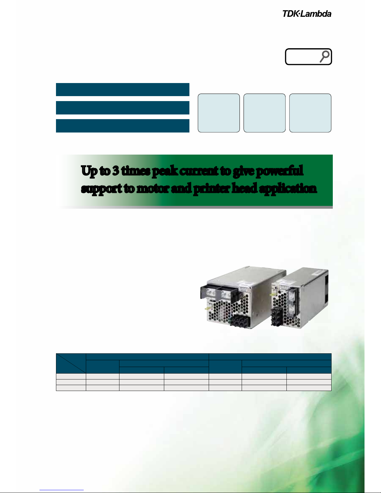
HWS-P
Support drive load with 3 times of peak power
AC/DC Switching power supply
with peak power capability
Factory
machiney
Textile
machinery,
Cash dispenser
Main applications
Line up
P69
Low acoustic noise with automated speed control fan
High power in compact size
Up to 3 times of peak current
High Reliability and User Friendly Power Supply for
Drive Load Application
The growth of motor and printer head applications, the center of
multifunction and high speed machineries, have been increased
from year to year. HWS-P is superior to provide function to sup-
port instant current in typical drive load with up to 3 times peak
current in compact size.
By taking into consideration on the demand of high reliability in-
dustrial equipment, elec. capacitor is expected to have 7 year of
life (Ta=40°)
. Also, 5 year warranty is provided.
The design include OCP circuit with shut off function, OVP circuit,
temperature sensor for automatic speed control fan as well as
built-in OTP circuit. All of these functions give a better safety and
ease to the users.
Mode
Output Voltage
HWS300P HWS600P
Ave. output
current
Peak current Ave. output
current
Peak current
100V input 200V input 100V input 200V input
24V 12.5A 21.0A 42.0A 25.0A 40.5A 83.0A
36V 8.4A 14.0A 28.0A 16.7A 27.0A 55.5A
48V 6.3A 10.5A 21.0A 12.5A 20.0A 41.5A
HWSSeries
Up to 3 times peak current to give powerful
support to motor and printer head application
Up to 3 times peak current to give powerful
support to motor and printer head application
Semiconductor
testing device

HWS 7
Specifications
HWS15 8
HWS30 10
HWS50 12
HWS80 14
HWS100 16
HWS150 18
HWS300 20
HWS600 22
HWS1000 24
HWS1500 26
HWS1800T 28
HWS/HD 31
Specifications
HWS30/HD 32
HWS50/HD 34
HWS100/HD 36
HWS150/HD 38
HWS300/HD 40
HWS600/HD 42
HWS1000/HD 44
HWS1500/HD 46
HWS1800T/HD 48
HWS/ME 51
Specifications
HWS30/ME 52
HWS50/ME 54
HWS100/ME 56
HWS150/ME 58
HWS300/ME 60
HWS600/ME 62
HWS1000/ME 64
HWS1500/ME 66
HWS-P 69
Specifications
HWS300P 70
HWS600P 72
HWS Series All 74
Block Diagram
HWS15, 30, 50, 80, 100, 150 74
HWS300, 600, 1000 75
HWS1500, 1800T 76
Sequence Time Chart
HWS300, 600, 1000 77
HWS1500, 1800T 78
Instruction Manual
HWS15, 30, 50, 80, 100, 150 79
HWS300, 600 85
HWS1000 93
HWS1500 104
HWS1800T 113
HWS300P, 600P 124
Contents

Instruction Manual
HWS HWS HD HWS ME HWS-P
■Applications
■Features
HWS
■ProductLineup
SingleOutput15W-1800W
Y
E
A
R
S
warranty
5
■Features
〔HWS15-150〕
HWS50−5/□□
■
ConformitytoRoHSDirective
■Modelnamingmethod
〔HWS300-1800〕
HWS300−5/□□
Instruction Manual
HWS HWS HD HWS ME HWS-P
ITEMS/UNITS MODEL HWS15-3 HWS15-5 HWS15-12 HWS15-15 HWS15-24 HWS15-48
Input
Voltage Range (*2) V AC85 - 265 or DC120 - 370
Frequency (*2) Hz 47 - 63
Efficiency (100/200VAC)(typ) (*1) 68 / 71 77 / 79 80 / 81 82 / 83 80 / 80
Current (100/200VAC)(typ) (*1) A 0.3 / 0.15 0.4 / 0.2
Inrush Current (100/200VAC)(typ) (*3)
A 14 / 28, Ta=25, cold start
Leakage Current (*10) mA Less than 0.5. (0.2 (typ) at 100VAC / 0.4 (typ) at 230VAC)
Output
Nominal Voltage VDC 3.3 5 12 15 24 48
Maximum Current A 3 1.3 1 0.65 0.33
Maximum Power W 10 15 15.6 15 15.6 15.8
Maximum Line Regulation (*5) mV 20 48 60 96 192
Maximum Load Regulation (*6) mV 40 96 120 192 384
Temperature Coefficient Less than 0.02% /
Maximum Ripple & Noise (0<Ta<70) (*4)
mVp-p
120 150 200
Maximum Ripple & Noise (10<Ta<0) (*4)
mVp-p
160 180 240
Hold-up Time (typ) (*9) ms 20
Voltage Adjustable Range VDC 2.97 - 3.96 4.0 - 6.0 9.6 - 14.4 12.0 - 18.0 19.2 - 28.8 38.4 - 52.8
Function
Over Current Protection (*7) A >3.15 >1.36 >1.05 >0.68 >0.34
Over Voltage Protection (*8) VDC 4.13 - 4.95 6.25 - 7.25 15.0 - 17.4 18.8 - 21.8 30.0 - 34.8 55.2 - 64.8
Remote Sensing -
Remote ON/OFF Control -
Parallel Operation -
Series Operation Possible
Line DIP Built to meet SEMI-F47 (200VAC Line only)
Environment
Operating Temperature (*11) -10 to +70 (-10 to +50: 100%, +60: 60%, +70: 20%)
Storage Temperature -30 to +85
Operating Humidity RH 30 - 90 (No dewdrop)
Storage Humidity RH 10 - 95 (No dewdrop)
Vibration At no operating, 10 - 55Hz (sweep for 1min)
19.6m/s² constant, X, Y, Z 1hour each.
Shock (In package) Less than 196.1m/s²
Cooling Convection cooling
Isolation Withstand Voltage Input - FG : 2kVAC (20mA), Input - Output : 3kVAC (20mA)
Output - FG : 500VAC (100mA) for 1min
Isolation Resistance More than 100Mat 25and 70%RH Output - FG : 500VDC
Standards
Safety Standards (*12) Approved by UL60950-1, CSA C22.2 No.60950-1, EN60950-1, EN50178 UL508 (with cover models only),
CSA C22.2 No.14-M95 (with cover models only) Built to meet UL508, DENAN
PFHC Built to meet IEC61000-3-2
EMI Built to meet EN55011/EN55022-B, FCC-B, VCCI-B
Immunity Built to meet IEC61000-4-2(Level 2,3), -3(Level 3), -4(Level 3),
-5(Level 3,4), -6(Level 3), -8(Level 4), -11
Mechanical
Weight (typ) g 180
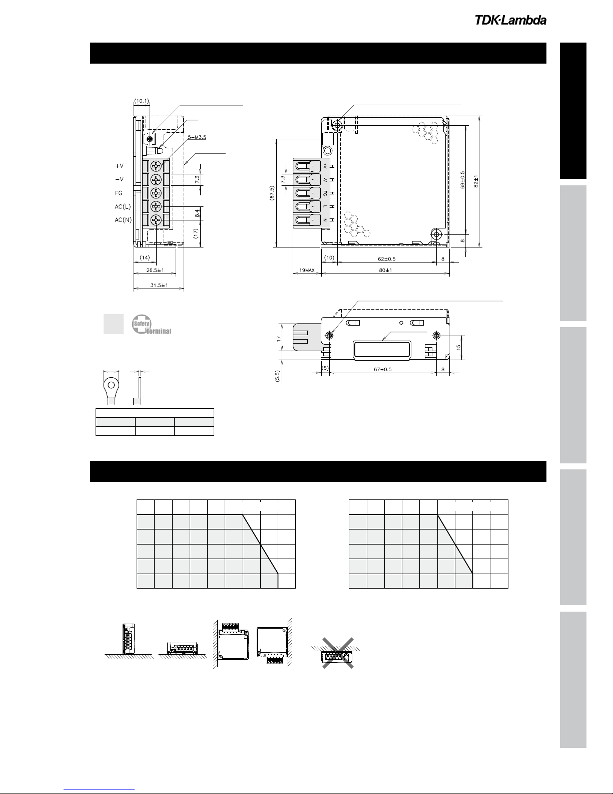
Size (W x H x D) mm 26.5 x 82 x 80 (Refer to outline drawing)
(*1) At 100/200VAC, Ta=25and maximum output power.
(*2) For cases where conformance to various safety specs (UL, CSA, EN) are required, to be described as 100 - 240VAC (50/60Hz).
(*3) Not applicable for the in-rush current to noise filter for less than 0.2ms.
(*4) Measure with JEITA RC-9131A probe, bandwidth of scope :100MHz.
For start up at low ambient temperature and low input voltage, output ripple noise might not meet specification.
However, there is no overshoot at start up and output ripple noise specification can be met after one second.
(*5) 85 - 265VAC, constant load.
(*6) No load-Full load, constant input voltage.
(*7) Foldback current limit with automatic recovery. Not operate at over load or dead short
condition for more than 30 seconds.
(*8) OVP circuit will shutdown output, manual reset (Re power on).
(*9) At 100/200VAC, Ta=25, nominal output voltage and maximum output current.
(*10) Measured by the each measuring method of UL, CSA, EN and DENAN (at 60Hz).
(*11) Ratings - Derating at standard mounting.
- Load (%) is percent of maximum output power or maximum output current, whichever is greater.
- As for other mountings, refer to derating curve.
(*12) As for DENAN, built to meet at 100VAC.
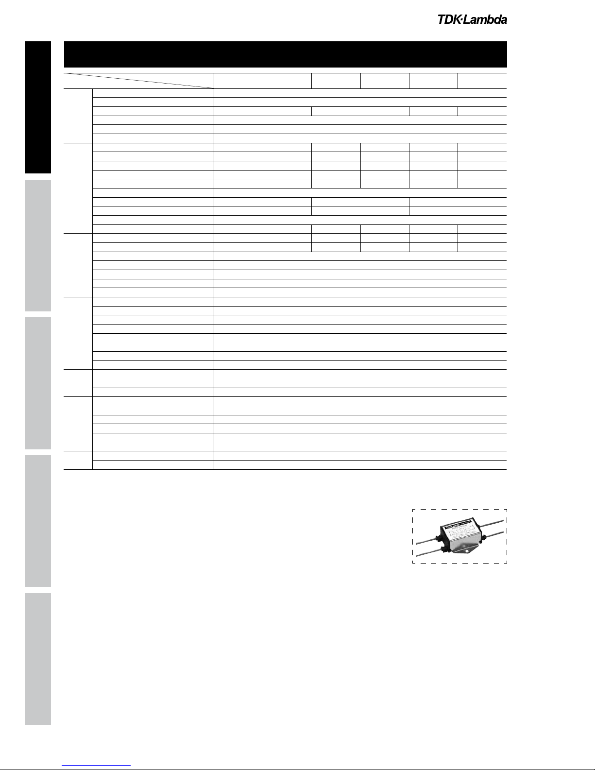
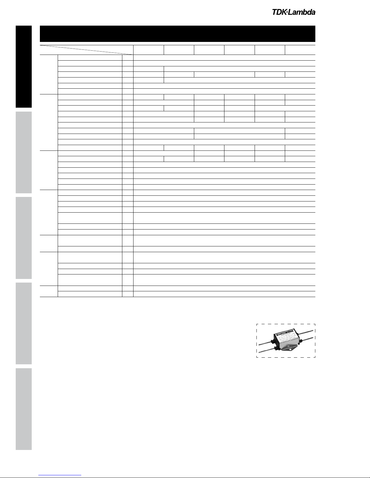
Pleasereferto"TDK-Lambda
EMCFilters"catalog.
●
RecommendedEMCFilter
HWS15 Specifications(Read instruction manual carefully, before using the power supply unit.)
HWS 15
Instruction Manual
HWS HWS HD HWS ME HWS-P
【HWS15】
D(max)t(max) Qty(max)
6.8mm 0.8mm 2pcs
Dt
VOLTAGEADJUSTMENT
COVER
(OPTION)
(WITHOUTCOVER)
(WITHCOVER)
NAMEPLATE
2-M3EMBOSSED,TAPPEDANDCOUNTERSUCKHOLES
SCREWPENETRATIONDEPTHMAX.6mm
2-M3TAPPEDHOLES
LED
unit:mm
RecommendedSolderlessTerminal
SCREWPENETRATIONDEPTHMAX.6mm
0
20
40
60
80
100
120
-10 0 10203040506070 80
MOUNTINGA,B,C,D
0
20
40
60
80
100
120
-10 0 10203040506070 80
Ta(°C)
MOUNTINGA,B,C,D
LOAD(%)
Ta(°C)
LOAD(%)
MOUNTINGA
(STANDARDMOUNTING)
MOUNTINGB MOUNTINGC MOUNTINGD DON'TUSE
HWS 15
Output Derating
Outline Drawing

Instruction Manual
HWS HWS HD HWS ME HWS-P
Pleasereferto"TDK-Lambda
EMCFilters"catalog.
●
RecommendedEMCFilter
(*1) At 100/200VAC, Ta=25and maximum output power.
(*2) For cases where conformance to various safety specs (UL, CSA, EN) are required, to be described as 100 - 240VAC (50/60Hz).
(*3) Not applicable for the in-rush current to noise filter for less than 0.2ms.
(*4) Measure with JEITA RC-9131A probe, bandwidth of scope :100MHz.
For start up at low ambient temperature and low input voltage, output ripple noise might not meet specification.
However, there is no overshoot at start up and output ripple noise specification can be met after one second.
(*5) 85 - 265VAC, constant load.
(*6) No load-Full load, constant input voltage.
(*7) Foldback current limit with automatic recovery. Not operate at over load or
dead short condition for more than 30 seconds.
(*8) OVP circuit will shutdown output, manual reset (re power on).
(*9) At 100/200VAC, Ta=25, nominal output voltage and maximum output current.
(*10) Measured by the each measuring method of UL, CSA, EN and DENAN (at 60Hz).
(*11) Ratings - Derating at standard mounting.
- Load (%) is percent of maximum output power or maximum output current, whichever is greater.
- As for other mountings, refer to derating curve.
(*12) As for DENAN, built to meet at 100VAC.
ITEMS/UNITS MODEL HWS30-3 HWS30-5 HWS30-12 HWS30-15 HWS30-24 HWS30-48
Input
Voltage Range (*2) V AC85 - 265 or DC120 - 370
Frequency (*2) Hz 47 - 63
Efficiency (100/200VAC)(typ) (*1) 70 / 73 77 / 80 81 / 83 83 / 86 82 / 83
Current (100/200VAC)(typ) (*1) A 0.6 / 0.3 0.8 / 0.4
Inrush Current (100/200VAC)(typ)(*3)
A 14 / 28, Ta=25, cold start
Leakage Current (*10) mA Less than 0.5. (0.2 (typ) at 100VAC / 0.4 (typ) at 230VAC)
Output
Nominal Voltage VDC 3.3 5 12 15 24 48
Maximum Current A 6 2.5 2 1.3 0.65
Maximum Power W 20 30 31.2
Maximum Line Regulation (*5) mV 20 48 60 96 192
Maximum Load Regulation (*6) mV 40 96 120 192 384
Temperature Coefficient Less than 0.02% /
Maximum Ripple & Noise (0≤Ta≤70) (*4)
mVp-p
120 150 200
Maximum Ripple & Noise (10≤Ta< 0) (*4)
mVp-p
160 180 240
Hold-up Time (typ) (*9) ms 20
Voltage Adjustable Range VDC 2.97 - 3.96 4.0 - 6.0 9.6 - 14.4 12.0 - 18.0 19.2 - 28.8 38.4 - 52.8
Function
Over Current Protection (*7) A >6.3 >2.62 >2.1 >1.36 >0.68
Over Voltage Protection (*8) VDC 4.13 - 4.95 6.25 - 7.25 15.0 - 17.4 18.8 - 21.8 30.0 - 34.8 55.2 - 64.8
Remote Sensing -
Remote ON/OFF Control -
Parallel Operation -
Series Operation Possible
Line DIP Built to meet SEMI-F47 (200VAC Line only)
Environment
Operating Temperature (*11) -10 to +70 (-10 to +50: 100%, +60: 60%, +70: 20%)
Storage Temperature -30 to +85
Operating Humidity RH 30 - 90 (No dewdrop)
Storage Humidity RH 10 - 95 (No dewdrop)
Vibration At no operating, 10 - 55Hz (sweep for 1min)
19.6m/s² constant, X, Y, Z 1hour each.
Shock (In package) Less than 196.1m/s²
Cooling Convection cooling
Isolation Withstand Voltage Input - FG : 2kVAC (20mA), Input - Output : 3kVAC (20mA)
Output - FG : 500VAC (100mA) for 1min
Isolation Resistance More than 100Mat 25and 70%RH Output - FG : 500VDC
Standards
Safety Standards (*12) Approved by UL60950-1, CSA C22.2 No.60950-1, EN60950-1, EN50178 UL508 (with cover models only),
CSA C22.2 No.14-M95 (with cover models only) Built to meet DENAN
PFHC Built to meet IEC61000-3-2
EMI Built to meet EN55011/EN55022-B, FCC-B, VCCI-B
Immunity Built to meet IEC61000-4-2(Level 2,3), -3(Level 3), -4(Level 3),
-5(Level 3,4), -6(Level 3), -8(Level 4), -11
Mechanical
Weight (typ) g 220
Size (W x H x D) mm 26.5 x 82 x 95 (Refer to outline drawing)
HWS30 Specifications(Read instruction manual carefully, before using the power supply unit.)
HWS 30

Instruction Manual
HWS HWS HD HWS ME HWS-P
【HWS30】
VOLTAGEADJUSTMENT
LED
NAMEPLATE
SEENOTEA
unit
COVER
(OPTION)
(WITHOUTCOVER)
(WITHCOVER)
RecommendedSolderlessTerminal
Qty(max)
2pcs
2-M3EMBOSSED,TAPPEDANDCOUNTERSUCKHOLES
SCREWPENETRATIONDEPTHMAX.6mm
2-M3TAPPEDHOLES
SCREWPENETRATIONDEPTHMAX.6mm
0
20
40
60
80
100
120
-10 0 10203040506070 80
0
20
40
60
80
100
120
-10 0 10203040506070 80
MOUNTINGA,B,C,D
Ta(°C)
MOUNTINGA,B,C,D
LOAD(%)
Ta(°C)
LOAD(%)
MOUNTINGA
(STANDARDMOUNTING)
MOUNTINGB MOUNTINGC MOUNTINGD DON'TUSE
Output Derating
Outline Drawing
HWS 30
Instruction Manual
HWS HWS HD HWS ME HWS-P
(*1) At 100/200VAC, Ta=25and maximum output power.
(*2) For cases where conformance to various safety specs (UL, CSA, EN) are required, to be described as 100 - 240VAC (50/60Hz).
(*3) Not applicable for the in-rush current to noise filter for less than 0.2ms.
(*4) Measure with JEITA RC-9131A probe, bandwidth of scope : 100MHz.
(*5) 85 - 265VAC, constant load.
(*6) No load-full load, constant input voltage.
(*7) Constant current limit and hiccup with automatic recovery. Not operate at over load
or dead short condition for more than 30 seconds.
(*8) OVP circuit will shutdown output, manual reset (re power on).
(*9) At 100/200VAC, nominal output voltage and maximum output current.
(*10) Measured by the each measuring method of UL, CSA, EN and DENAN (at 60Hz).
(*11) Ratings - Derating at standard mounting.
- Load (%) is percent of maximum output power or maximum output current, whichever is greater.
- As for other mountings, refer to derating curve.
(*12) As for DENAN, built to meet at 100VAC.
Pleasereferto"TDK-Lambda
EMCFilters"catalog.
●
RecommendedEMCFilter
ITEMS/UNITS MODEL HWS50-3 HWS50-5 HWS50-12 HWS50-15 HWS50-24 HWS50-48
Input
Voltage Range (*2) V AC85 - 265 or DC120 - 370
Frequency (*2) Hz 47 - 63
Power Factor (100/200VAC)(typ) (*1)
0.98 / 0.90 0.99 / 0.95
Efficiency (100/200VAC)(typ) (*1) 76 / 78 82 / 84 81 / 83 82 / 84 83 / 85
Current (100/200VAC)(typ) (*1) A 0.5 / 0.25 0.7 / 0.35
Inrush Current (100/200VAC)(typ)
(*3) A 14 / 28, Ta=25, cold start
Leakage Current (*10) mA Less than 0.5. (0.2 (typ) at 100VAC / 0.4 (typ) at 230VAC)
Output
Nominal Voltage V 3.3 5 12 15 24 48
Maximum Current A 10 4.3 3.5 2.2 1.1
Maximum Power W 33 50 51.6 52.5 52.8
Maximum Line Regulation (*5) mV 20 48 60 96 192
Maximum Load Regulation (*6) mV 40 96 120 192 384
Temperature Coefficient Less than 0.02% /
Maximum Ripple & Noise
(0
≤
Ta
≤
70) (*4)
mVp-p
120 150 200
Maximum Ripple & Noise (
10
≤
Ta< 0) (*4)
mVp-p
160 180 240
Hold-up Time (typ) (*9) ms 20
Voltage Adjustable Range VDC 2.97 - 3.96 4.0 - 6.0 9.6 - 14.4 12.0 - 18.0 19.2 - 28.8 38.4 - 52.8
Function
Over Current Protection (*7) A >10.5 >4.51 >3.67 >2.31 >1.15
Over Voltage Protection (*8) V 4.13 - 4.95 6.25 - 7.25 15.0 - 17.4 18.8 - 21.8 30.0 - 34.8 55.2 - 64.8
Remote Sensing -
Remote ON/OFF Control Possible (/R Option)
Parallel Operation -
Series Operation Possible
Line DIP Built to meet SEMI-F47 (200VAC Line only)
Environment
Operating Temperature (*11) -10 to +70 (-10 to +50: 100%, +60: 60%, +70: 20%)
Storage Temperature -30 to +85
Operating Humidity RH 30 - 90 (No dewdrop)
Storage Humidity RH 10 - 95 (No dewdrop)
Vibration At no operating, 10 - 55Hz (sweep for 1min) 19.6m/s² constant,
X, Y, Z 1hour each.
Shock (In package) Less than 196.1m/s²
Cooling Convection cooling
Isolation Withstand Voltage Input - FG : 2kVAC (20mA), Input - Output : 3kVAC (20mA)
Output - FG : 500VAC (100mA) for 1min
Isolation Resistance More than 100Mat 25and 70%RH Output - FG : 500VDC
Standards
Safety Standards (*12) Approved by UL60950-1, CSA C22.2 No.60950-1, EN60950-1, EN50178 UL508 (with cover models only),
CSA C22.2 No.14-M95 (with cover models only) Built to meet DENAN
PFHC Built to meet IEC61000-3-2
EMI Built to meet EN55011/EN55022-B, FCC-B, VCCI-B
Immunity Built to meet IEC61000-4-2(Level 2,3), -3(Level 3), -4(Level 3), -
5(Level 3,4), -6(Level 3), -8(Level 4), -11
Mechanical
Weight (typ) g 280
Size (W x H x D) mm 26.5 x 82 x 120 (Refer to outline drawing)
HWS50 Specifications(Read instruction manual carefully, before using the power supply unit.)
HWS 50

Instruction Manual
HWS HWS HD HWS ME HWS-P
【HWS50】
VOLTAGEADJUSTMENT
LED
COVER
(OPTION)
REMOTEON/OFFCONTROLCONNECTOR(SEENOTEA)
2-M3TAPPEDHOLES
SCREWPENETRATIONDEPTHMAX.6mm
2-M3EMBOSSED,TAPPEDANDCOUNTERSUNKHOLES
NAMEPLATE
UNIT:mm
(WITHOUTCOVER)
(WITHCOVER)
RecommendedSolderlessTerminal
Qty(max)
2pcs
0
20
40
60
80
100
120
-10 0 10203040506070 80
MOUNTINGA,B
MOUNTINGC,D
0
20
40
60
80
100
120
-10 0 10203040506070 80
Ta(℃)
MOUNTINGA,B
MOUNTINGC,D
LOAD(%)
LOAD(%)
Ta(℃)
MOUNTINGA
(STANDARDMOUNTING)
MOUNTINGB
MOUNTINGC MOUNTINGD
DONTUSE
HWS 50
Output Derating
Outline Drawing

Instruction Manual
HWS HWS HD HWS ME HWS-P
HWS80 Specifications(Read instruction manual carefully, before using the power supply unit.)
ITEMS/UNITS MODEL HWS80-3 HWS80-5 HWS80-12 HWS80-15 HWS80-24 HWS80-48
Input
Voltage Range (*2) V AC85 - 265 or DC120 - 370
Frequency (*2) Hz 47 - 63
Power Factor (100/200VAC)(typ) (*1)
0.98 / 0.90 0.99 / 0.95
Efficiency (100/200VAC)(typ) (*1) 77 / 79 82 / 85 83 / 85 84 / 86
Current (100/200VAC)(typ) (*1) A 0.72 / 0.36 1.04 / 0.52
Inrush Current (100/200VAC)(typ) (*3)
A 14 / 28, Ta=25, cold start
Leakage Current (*10) mA Less than 0.5. (0.2 (typ) at 100VAC / 0.4 (typ) at 230VAC)
Output
Nominal Voltage VDC 3.3 5 12 15 24 48
Maximum Current A 16 6.7 5.4 3.4 1.7
Maximum Power W 52.8 80 80.4 81 81.6
Maximum Line Regulation (*5) mV 20 48 60 96 192
Maximum Load Regulation (*6) mV 40 96 120 192 384
Temperature Coefficient Less than 0.02% /
Maximum Ripple & Noise (0≤Ta≤70) (*4)
mVp-p
120 150 200
Maximum Ripple & Noise (10
≤
Ta< 0) (*4)
mVp-p
160 180 240
Hold-up Time (typ) (*9) ms 20ms
Voltage Adjustable Range VDC 2.97 - 3.96 4.0 - 6.0 9.6 - 14.4 12.0 - 18.0 19.2 - 28.8 38.4 - 52.8
Function
Over Current Protection (*7) A >16.8 >7.04 >5.67 >3.57 >1.79
Over Voltage Protection (*8) VDC 4.13 - 4.95 6.25 - 7.25 15.0 - 17.4 18.8 - 21.8 30.0 - 34.8 55.2 - 64.8
Remote Sensing Possible
Remote ON/OFF Control Possible (/R Option)
Parallel Operation -
Series Operation Possible
Line DIP Built to meet SEMI-F47 (200VAC Line only)
Environment
Operating Temperature (*11) -10 to +70 (-10 to +50: 100%, +60: 60%, +70: 20%)
Storage Temperature -30 to +85
Operating Humidity RH 30 - 90 (No dewdrop)
Storage Humidity RH 10 - 95 (No dewdrop)
Vibration At no operating, 10 - 55Hz (sweep for 1min)
19.6m/s² constant, X, Y, Z 1hour each.
Shock (In package) Less than 196.1m/s²
Cooling Convection cooling
Isolation Withstand Voltage Input - FG : 2kVAC (20mA), Input - Output : 3kVAC (20mA)
Output - FG : 500VAC (100mA) for 1min
Isolation Resistance More than 100Mat 25and 70%RH Output - FG : 500VDC
Standards
Safety Standards (*12) Approved by UL60950-1, CSA C22.2 No.60950-1, EN60950-1, EN50178 UL508 (with cover models only),
CSA C22.2 No.14-M95 (with cover models only) Built to meet DENAN
PFHC Built to meet IEC61000-3-2
EMI Built to meet EN55011/EN55022-B, FCC-B, VCCI-B
Immunity Built to meet IEC61000-4-2(Level 2,3), -3(Level 3), -4(Level 3),
-5(Level 3,4), -6(Level 3), -8(Level 4), -11
Mechanical
Weight (typ) g 450
Size (W x H x D) mm 28 x 82 x 160 (Refer to outline drawing)
(*1) At 100/200VAC, Ta=25and maximum output power.
(*2) For cases where conformance to various safety specs (UL, CSA, EN) are required, to be described as 100 - 240VAC (50/60Hz).
(*3) Not applicable for the in-rush current to noise filter for less than 0.2ms.
(*4) Measure with JEITA RC-9131A probe, bandwidth of scope : 100MHz.
(*5) 85 - 265VAC , constant load.
(*6) No load-full load, constant input voltage.
(*7) Constant current limit and hiccup with automatic recovery. Not operate at over load or
dead short condition for more than 30 seconds.
(*8) OVP circuit will shutdown output, manual reset (re power on).
(*9) At 100/200VAC, nominal output voltage and maximum output current.
(*10) Measured by the each measuring method of UL, CSA, EN and DENAN (at 60Hz).
(*11) Ratings - Derating at standard mounting.
- Load (%) is percent of maximum output power or maximum output current, whichever is greater.
- As for other mountings, refer to derating curve.
(*12) As for DENAN, built to meet at 100VAC.
Pleasereferto"TDK-Lambda
EMCFilters"catalog.
●
RecommendedEMCFilter
HWS 80
Instruction Manual
HWS HWS HD HWS ME HWS-P
【HWS80】
NAMEPLATE
SCREWPENETRATIONDEPTHMAX.6mm
unit:mm
VOLTAGEADJUSTMENT
LED
COVER
(OPTION)
(WITHCOVER)
(WITHOUTCOVER)
RecommendedSolderlessTerminal
Qty(max)
2pcs
1pc
2pcs
Others
Terminal
REMOTEON/OFFCONTROLCONNECTOR(SEENOTEA)
2-M3TAPPEDHOLES
SCREWPENETRATIONDEPTHMAX.6mm
2-M3EMBOSSED,TAPPEDANDCOUNTERSUNKHOLES
0
20
40
60
80
100
120
-10 0 10203040506070 80
Ta(℃)
MOUNTINGA
MOUNTINGB,C,D
LOAD(%)
MOUNTINGA
(STANDARDMOUNTING)
MOUNTINGB
MOUNTINGC MOUNTINGD
DONTUSE
0
20
40
60
80
100
120
-10 0 10203040506070 80
Ta(℃)
MOUNTINGA
MOUNTINGB,C,D
LOAD(%)
HWS 80
Outline Drawing
Output Derating

Instruction Manual
HWS HWS HD HWS ME HWS-P
ITEMS/UNITS MODEL HWS100-3 HWS100-5 HWS100-12 HWS100-15 HWS100-24 HWS100-48
Input
Voltage Range (*2) V AC85 - 265 or DC120 - 370
Frequency (*2) Hz 47 - 63
Power Factor (100/200VAC)(typ) (*1)
0.98 / 0.90 0.99 / 0.95
Efficiency (100/200VAC)(typ) (*1) 78 / 81 83 / 86 84 / 87
Current (100/200VAC)(typ) (*1) A 0.9 / 0.45 1.3 / 0.65
Inrush Current (100/200VAC)(typ) (*3)
A 14 / 28, Ta=25, cold start
Leakage Current (*10) mA Less than 0.5. (0.2 (typ) at 100VAC / 0.4 (typ) at 230VAC)
Output
Nominal Voltage VDC 3.3 5 12 15 24 48
Maximum Current A 20 8.5 7 4.5 2.1
Maximum Power W 66 100 102 105 108 100.8
Maximum Line Regulation (*5) mV 20 48 60 96 192
Maximum Load Regulation (*6) mV 40 96 120 192 384
Temperature Coefficient Less than 0.02% /
Maximum Ripple & Noise (0≤Ta≤70)(*4)
mVp-p
120 150 200
Maximum Ripple & Noise (10≤Ta< 0)(*4)
mVp-p
160 180 240
Hold-up Time (typ) (*9) ms 20
Voltage Adjustable Range VDC 2.97 - 3.96 4.0 - 6.0 9.6 - 14.4 12.0 - 18.0 19.2 - 28.8 38.4 - 52.8
Function
Over Current Protection (*7) A >21.0 >8.92 >7.35 >4.72 >2.20
Over Voltage Protection (*8) VDC 4.13 - 4.95 6.25 - 7.25 15.0 - 17.4 18.8 - 21.8 30.0 - 34.8 55.2 - 64.8
Remote Sensing Possible
Remote ON/OFF Control Possible (/R Option)
Parallel Operation -
Series Operation Possible
Line DIP Built to meet SEMI-F47 (200VAC Line only)
Environment
Operating Temperature (*11) -10 to +70 (-10 to +50: 100%, +60: 60%, +70: 20%)
Storage Temperature -30 to +85
Operating Humidity RH 30 - 90 (No dewdrop)
Storage Humidity RH 10 - 95 (No dewdrop)
Vibration At no operating, 10 - 55Hz (sweep for 1min) 19.6m/s² constant,
X, Y, Z 1hour each.
Shock (In package) Less than 196.1m/s²
Cooling Convection cooling
Isolation Withstand Voltage Input - FG : 2kVAC (20mA), Input - Output : 3kVAC (20mA)
Output - FG : 500VAC (100mA) for 1min
Isolation Resistance More than 100Mat 25and 70%RH Output - FG : 500VDC
Standards
Safety Standards (*12) Approved by UL60950-1, CSA C22.2 No.60950-1, EN60950-1, EN50178 UL508 (with cover models only),
CSA C22.2 No.14-M95 (with cover models only) Built to meet, DENAN
PFHC Built to meet IEC61000-3-2
EMI Built to meet EN55011/EN55022-B, FCC-B, VCCI-B
Immunity Built to meet IEC61000-4-2(Level 2,3), -3(Level 3), -4(Level 3),
-5(Level 3,4), -6(Level 3), -8(Level 4), -11
Mechanical
Weight (typ) g 450
Size (W x H x D) mm 28 x 82 x 160 (Refer to outline drawing)
(*1) At 100/200VAC, Ta=25and maximum output power.
(*2) For cases where conformance to various safety specs (UL, CSA, EN) are required, to be described as 100 - 240VAC (50/60Hz).
(*3) Not applicable for the in-rush current to noise filter for less than 0.2ms.
(*4) Measure with JEITA RC-9131A probe, bandwidth of scope :100MHz.
(*5) 85 - 265VAC, constant load.
(*6) No load-Full load, constant input voltage.
(*7) Constant current limit and hiccup with automatic recovery.
Not operate at over load or dead short condition for more than 30 seconds.
(*8) OVP circuit will shutdown output, manual reset (re power on).
(*9) At 100/200VAC, nominal output voltage and maximum output current.
(*10) Measured by the each measuring method of UL, CSA, EN and DENAN (at 60Hz).
(*11) Ratings - Derating at standard mounting.
- Load (%) is percent of maximum output power or maximum output current, whichever is greater.
- As for other mountings, refer to derating curve
(*12) As for DENAN, built to meet at 100VAC.
●
RecommendedEMCFilter
Pleasereferto"TDK-Lambda
EMCFilters"catalog.
HWS 100
HWS100 Specifications(Read instruction manual carefully, before using the power supply unit.)

Instruction Manual
HWS HWS HD HWS ME HWS-P
【HWS100】
VOLTAGEADJUSTMENT
COVER
(OPTION)
LED
(WITHOUTCOVER)
(WITHCOVER)
NAMEPLATE
unit
RecommendedSolderlessTerminal
Qty(max)
2pcs
1pc
2pcs
Others
Terminal
SCREWPENETRATIONDEPTHMAX.6mm
REMOTEON/OFFCONTROLCONNECTOR(SEENOTEA)
2-M3TAPPEDHOLES
SCREWPENETRATIONDEPTHMAX.6mm
2-M3EMBOSSED,TAPPEDANDCOUNTERSUNKHOLES
0
20
40
60
80
100
120
-10 0 10203040506070 80
Ta(℃)
MOUNTINGA
MOUNTINGB,C,D
LORD(%)
MOUNTINGA
(STANDARDMOUNTING)
MOUNTINGB
MOUNTINGC MOUNTINGD
DONTUSE
0
20
40
60
80
100
120
-10 0 10203040506070 80
Ta(℃)
MOUNTINGA
MOUNTINGB,C,D
LORD(%)
HWS 100
Outline Drawing
Output Derating

Instruction Manual
HWS HWS HD HWS ME HWS-P
(*1) At 100/200VAC, Ta=25and maximum output power.
(*2) For cases where conformance to various safety specs (UL, CSA, EN) are required, to be described as 100 - 240VAC (50/60Hz).
(*3) Not applicable for the in-rush current to noise filter for less than 0.2ms.
(*4) Measure with JEITA RC-9131A probe, bandwidth of scope : 100MHz.
(*5) 85 - 265VAC, constant load.
(*6) No load-full load, constant input voltage.
(*7) Constant current limit and hiccup with automatic recovery.
Not operate at over load or dead short condition for more than 30 seconds.
(*8) OVP circuit will shutdown output, manual reset (re power on).
(*9) At 100/200VAC, nominal output voltage and maximum output current.
(*10) Measured by the each measuring method of UL, CSA, EN and DENAN (at 60Hz).
(*11) Ratings - Derating at standard mounting.
- Load (%) is percent of maximum output power or maximum output current, whichever is greater.
- As for other mountings, refer to derating curve.
(*12) As for DENAN, built to meet at 100VAC.
Pleasereferto"TDK-Lambda
EMCFilters"catalog.
●
RecommendedEMCFilter
ITEMS/UNITS MODEL HWS150-3 HWS150-5 HWS150-12 HWS150-15 HWS150-24 HWS150-48
Input
Voltage Range (*2) V AC85 - 265 or DC120 - 370
Frequency (*2) Hz 47 - 63
Power Factor (100/200VAC)(typ) (*1)
0.98 / 0.90 0.99 / 0.95
Efficiency (100/200VAC)(typ) (*1) 78 / 81 83 / 86 85 / 88
Current (100/200VAC)(typ) (*1) A 1.3 / 0.65 1.9 / 0.95
Inrush Current (100/200VAC)(typ) (*3)
A 14 / 28, Ta=25, cold start
Leakage Current (*10) mA Less than 0.5. (0.2 (typ) at 100VAC / 0.4 (typ) at 230VAC)
Output
Nominal Voltage V 3.3 5 12 15 24 48
Maximum Current A 30 13 10 6.5 3.3
Maximum Power W 99 150 156 150 156 158.4
Maximum Line Regulation (*5) mV 20 48 60 96 192
Maximum Load Regulation (*6) mV 40 96 120 192 384
Temperature Coefficient Less than 0.02% /
Maximum Ripple & Noise (0≤Ta≤70) (*4)
mVp-p
120 150 200
Maximum Ripple & Noise (10≤Ta< 0) (*4)
mVp-p
160 180 240
Hold-up Time (typ) (*9) ms 20
Voltage Adjustable Range VDC 2.97 - 3.96 4.0 - 6.0 9.6 - 14.4 12.0 - 18.0 19.2 - 28.8 38.4 - 52.8
Function
Over Current Protection (*7) A >31.5 >13.6 >10.5 >6.82 >3.46
Over Voltage Protection (*8) V 4.13 - 4.95 6.25 - 7.25 15.0 - 17.4 18.8 - 21.8 30.0 - 34.8 55.2 - 64.8
Remote Sensing (*8) Possible
Remote ON/OFF Control Possible (/R Option)
Parallel Operation -
Series Operation Possible
Line DIP Built to meet SEMI-F47 (200VAC Line only)
Environment
Operating Temperature (*11) -10 to +70 (-10 to +50: 100%, +60: 60%, +70: 20%)
Storage Temperature -30 to +85
Operating Humidity RH 30 - 90 (No dewdrop)
Storage Humidity RH 10 - 95 (No dewdrop)
Vibration At no operating, 10 - 55Hz (sweep for 1min) 19.6m/s² constant,
X, Y, Z 1hour each.
Shock (In package) Less than 196.1m/s²
Cooling Convection cooling
Isolation Withstand Voltage Input - FG : 2kVAC (20mA), Input - Output : 3kVAC (20mA)
Output - FG : 500VAC (100mA) for 1min
Isolation Resistance More than 100Mat 25and 70%RH Output - FG : 500VDC
Standards
Safety Standards (*12) Approved by UL60950-1, CSA C22.2 No.60950-1, EN60950-1, EN50178 UL508 (with cover models only),
CSA C22.2 No.14-M95 (with cover models only)Built to meet DENAN
PFHC Built to meet IEC61000-3-2
EMI Built to meet EN55011/EN55022-B, FCC-B, VCCI-B
Immunity Built to meet IEC61000-4-2(Level 2,3), -3(Level 3), -4(Level 3),
-5(Level 3,4), -6(Level 3), -8(Level 4), -11
Mechanical
Weight (typ) g 500
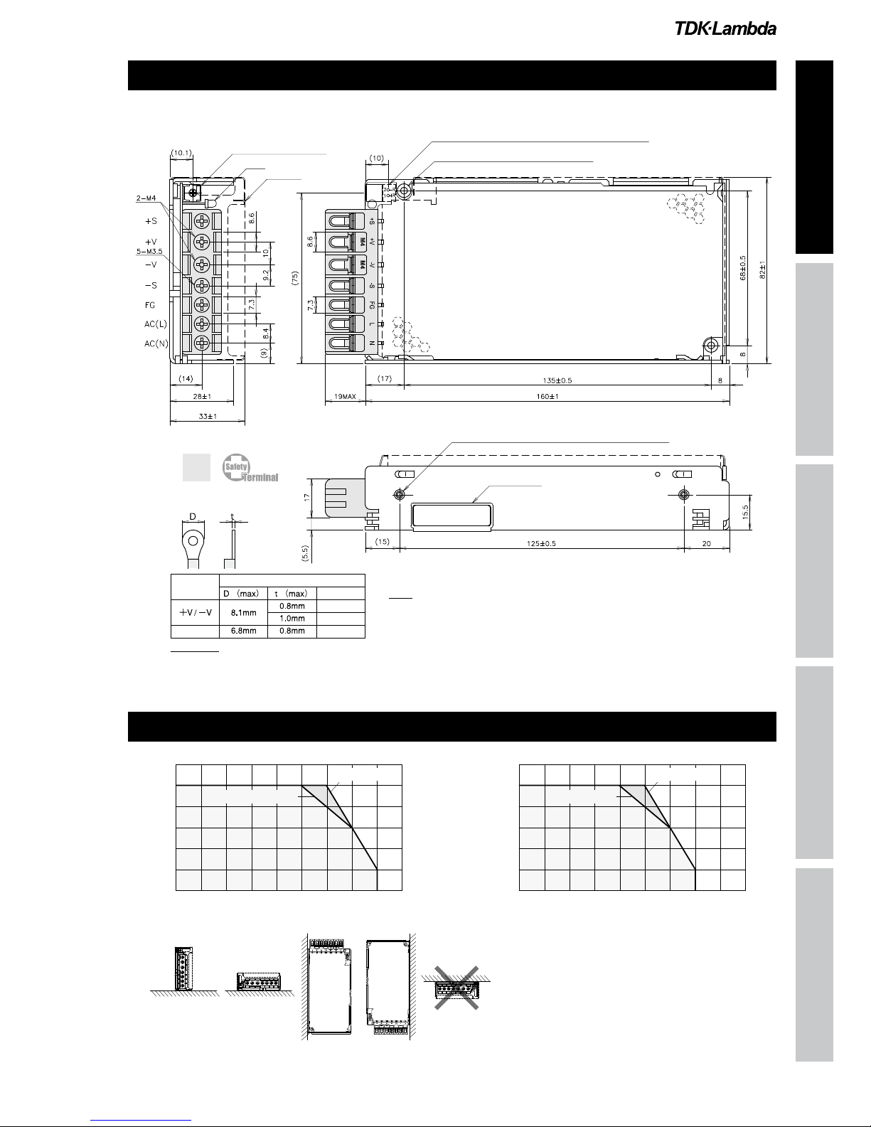
Size (W x H x D) mm 37 x 82 x 160 (Refer to outline drawing)
HWS 150
HWS150 Specifications(Read instruction manual carefully, before using the power supply unit.)

Instruction Manual
HWS HWS HD HWS ME HWS-P
【HWS150】
Terminal
D(max)t(max) Qty(max)
+V/−V8.1mm 0.8mm 2pcs
1.0mm 1pc
Others 6.8mm 0.8mm 2pcs
Dt
VOLTAGEADJUSTMENT
LED
COVER
(OPTION)
NAMEPLATE
unit:mm
(WITHOUTCOVER)
(WITHCOVER)
RecommendedSolderlessTerminal
SCREWPENETRATIONDEPTHMAX.6mm
REMOTEON/OFFCONTROLCONNECTOR(SEENOTEA)
2-M3TAPPEDHOLES
SCREWPENETRATIONDEPTHMAX.6mm
2-M3EMBOSSED,TAPPEDANDCOUNTERSUNKHOLES
0
20
40
60
80
100
120
-10 0 10203040506070 80
MOUNTINGB
MOUNTINGA
MOUNTINGC,D
Ta(°C)
LOAD(%)
MOUNTINGA
(STANDARDMOUNTING)
MOUNTINGB
MOUNTINGC MOUNTINGD
DON'TUSE
0
20
40
60
80
100
120
-10 0 10 20 25 30 40 50 60 70 80
MOUNTINGA
Ta(°C)
LOAD(%)
MOUNTINGB,C,D
HWS 150
Output Derating
Outline Drawing

Instruction Manual
HWS HWS HD HWS ME HWS-P
ITEMS/UNITS MODEL HWS300-3 HWS300-5 HWS300-12 HWS300-15 HWS300-24 HWS300-48
Input
Voltage Range (*2) V AC85 - 265 or DC120 - 330
Frequency (*2) Hz 47 - 63
Power Factor (100/200VAC)(typ) (*1)
0.99 / 0.95
Efficiency (100/200VAC)(typ) (*1) 74 / 77 79 / 82 80 / 83 82 / 85
Current (100/200VAC)(typ) (*1) A 2.7 / 1.4 3.8 / 1.9 4.1 / 2.1
Inrush Current (100/200VAC)(typ) (*3)
A 20 / 40
Leakage Current (*10) mA Less than 0.75. (0.2 (typ) at 100VAC / 0.44 (typ) at 230VAC)
Output
Nominal Voltage VDC 3.3 5 12 15 24 48
Maximum Current (*13) A 60 27 22 14 (16.5) 7
Maximum Power W 198 300 324 330 336
Maximum Line Regulation (*5) mV 20 48 60 96 192
Maximum Load Regulation (*6) mV 30 72 90 144 288
Temperature Coefficient Less than 0.02% /
Maximum Ripple & Noise (0≤Ta≤70) (*4)
mVp-p
120 150 350
Maximum Ripple & Noise (10≤Ta< 0) (*4)
mVp-p
180 200 400
Hold-up Time (typ) (*9) ms 20
Voltage Adjustable Range VDC 2.64 - 3.96 4.0 - 6.0 9.6 - 14.4 12.0 - 18.0 19.2 - 28.8 38.4 - 52.8
Function
Over Current Protection (*7) A >63 > 28.4 >23.1 >16.7 >7.4
Over Voltage Protection (*8) V 4.13 - 4.95 6.25 - 7.25 15.0 - 17.4 18.8 - 21.8 30.0 - 34.8 55.2 - 64.8
Remote Sensing Possible
Remote ON/OFF Control Possible
Parallel Operation Possible
Series Operation Possible
Monitoring Signal PF (Open collector output)
Line DIP Designed to meet SEMI-F47 (200VAC Line only)
Environment
Operating Temperature (*11) -10 to +70 (-10 to +50: 100%, +70: 50%)
Storage Temperature -30 to +85
Operating Humidity RH 10 - 90 (No dewdrop)
Storage Humidity RH 10 - 95 (No dewdrop)
Vibration At no operating, 10 - 55Hz (sweep for 1min) 19.6m/s² constant,
X, Y, Z 1hour each.
Shock (In package) Less than 196.1m/s²
Cooling Forced air by blower fan
Isolation
Withstand Voltage Input - FG : 2.5kVAC (20mA), Input - Output : 3kVAC (20mA)
Output - FG: 500VAC (100mA), Output-CNT: 100VAC(100mA) for 1min
Isolation Resistance More than 100MOutput - FG : 500VDC
More than 10MOutput -CNT : 100VDC at 25and 70%RH
Standards
Safety Standards (*12) Approved by UL60950-1, UL508 (24V model only), CSA C22.2 No.60950-1,
CSA C22.2 No.14-M95 (24V model only), EN60950-1, EN50178 Designed to meet DENAN
PFHC Designed to meet IEC61000-3-2
EMI Designed to meet EN55011/EN55022-B, FCC-B, VCCI-B
Immunity Designed to meet IEC61000-4-2(Level 2,3), -3(Level 3), -4(Level3),
-5(Level 3,4), -6(Level 3), -8(Level 4), -11
Mechanical
Weight (typ) g 1000
Size (W x H x D) mm 61 x 82 x 165 (Refer to outline drawing)
(*1) At 100/200VAC, Ta=25and maximum output power.
(*2) For cases where conformance to various safety specs (UL, CSA, EN) are required, to be described as 100-240VAC (50/60Hz).
(*3) Not applicable for the inrush current to noise filter for less than 0.2ms.
(*4) Measure with JEITA RC-9131A probe, bandwidth of scope :100MHz.
(*5) 85 - 265VAC, constant load.
(*6) No load-full load, constant input voltage.
(*7) 3.3, 5V model: Constant current limit and hiccup with automatic recovery.
12 - 48V model: Constant current limit with automatic recovery.
Avoid to operate at over load or short circuit condition for more than 30 seconds.
(*8) OVP circuit will shut the output down, manual reset (CNT reset or Re power on).
(*9) At 100/200VAC, nominal output voltage and maximum output current.
(*10) Measured by the each measuring method of UL, CSA, EN and DENAN (at 60Hz), Ta=25.
(*11) Ratings - Derating at standard mounting. Refer to output derating curve.
- Load (%) is percent of maximum output power or maximum output current, whichever is greater.
(*12) As for DENAN, designed to meet at 100VAC.
(*13) ( ): Peak output current at 200VAC. Operaing time at peak output is less than 10 sec, duty is less than 35%.
Pleasereferto"TDK-Lambda
EMCFilters"catalog.
●
RecommendedEMCFilter
HWS 300
HWS300 Specifications(Read instruction manual carefully, before using the power supply unit.)
This manual suits for next models
37
Table of contents
Other TDK-Lambada Power Supply manuals

Popular Power Supply manuals by other brands


Altronix
Altronix AL624ET installation instructions

Allen-Bradley
Allen-Bradley Series B installation instructions

Siemens
Siemens 4AV2306-2EB00-0A operating instructions

Shell
Shell SPS-500-01 manual

Rockwell Automation
Rockwell Automation 1606-XLE960 instruction manual

Puls
Puls QS10.481-C1 installation manual