manuals.online logo
Brands
  1. Home
  2. •
  3. Brands
  4. •
  5. TE Connectivity
  6. •
  7. Accessories
  8. •
  9. TE Connectivity LGA4189 User manual

TE Connectivity LGA4189 User manual

LGA4189 Socket Instruction
Sheet
411-115008 Rev.A
20th Mar’20
TE Connectivity Confidential & Proprietary. Do not reproduce or distribute.
LGA4189 Socket is designed to receive the
4189 position LGApackage. Read these
instructions thoroughly before installing the
package onto the socket. This sheet covers
the instruction after SMT till package
installation.
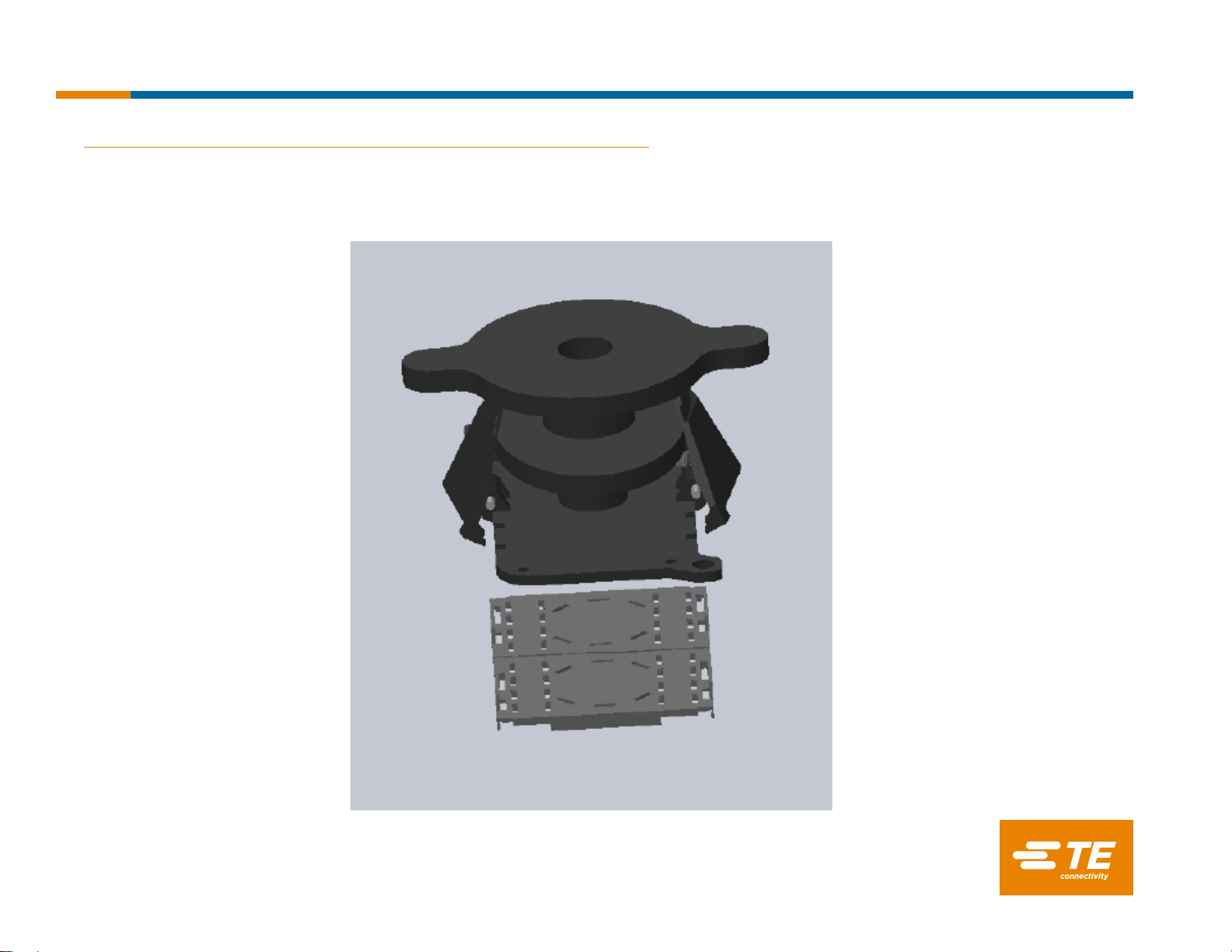
TE provides five components for LGA4189
socket system. socket(Fig.2a),bolster
assembly(Fig.2b),back plate(Fig.2c),carrier
(Fig.2d), and dust cover(Fig.2e).
These components shall be used correctly to
secure electrical and mechanical quality.
1. Introduction
Fig.1 System of LGA 4189 socket
2
Dust cover
Heatsink
Processor Carrier
Processor
Bolster Plate Assembly
LGA4189
Back plate
Instruction Sheet
411-115008 Rev.A
20th Mar’20
TE Connectivity Confidential & Proprietary. Do not reproduce or distribute.
2. Components
These components shall be used correctly to secure electrical and mechanical quality.
Please refer the instruction sheet shown in the table below.
Description Part Number(*1)
1) LGA4189Socket Individual Package P/N X-2324271-X
Kit Package P/N X-2332283-X
2) Bolster Plate X-2330550-X
3) Back plate Assy X-2330551-X
4) Carrier X-2330552-X
5) Dust Cover 2-2330553-1
3
Fig.2a Socket assy Fig.2b Bolster Plate Fig.2c Back plate Fig.2d Carrier Fig.2e Dust cover
Instruction Sheet
411-115008 Rev.A
20th Mar’20
TE Connectivity Confidential & Proprietary. Do not reproduce or distribute.
3. Attachment hardwareAssy and back plate Assy procedure
3.1 Prepare components
Below three components are used.
Fig.3
4
Socket P4 Back plate
Pin 1 indicators
Bolster plate
Instruction Sheet
411-115008 Rev.A
20th Mar’20
TE Connectivity Confidential & Proprietary. Do not reproduce or distribute.
3. Attachment hardware Assy and back plate Assy procedure
3.2 Assemble back plate on PCB
Attach back plate to PCB from back side. 6 stud bolts go through applicable 6 holes
of PCB. (Pin 1 indicators)
Please confirm if there are any foreign object or irregular warpage of PCB
5
Socket P4
H5
Fig.4
H4
H6 H3
H2
H1
S5 S4
S6 S3
S1 S2
Pin 1 indicators Pin 1 indicators
Instruction Sheet
411-115008 Rev.A
20th Mar’20
TE Connectivity Confidential & Proprietary. Do not reproduce or distribute.
3. Attachment hardware Assy and back plate Assy procedure
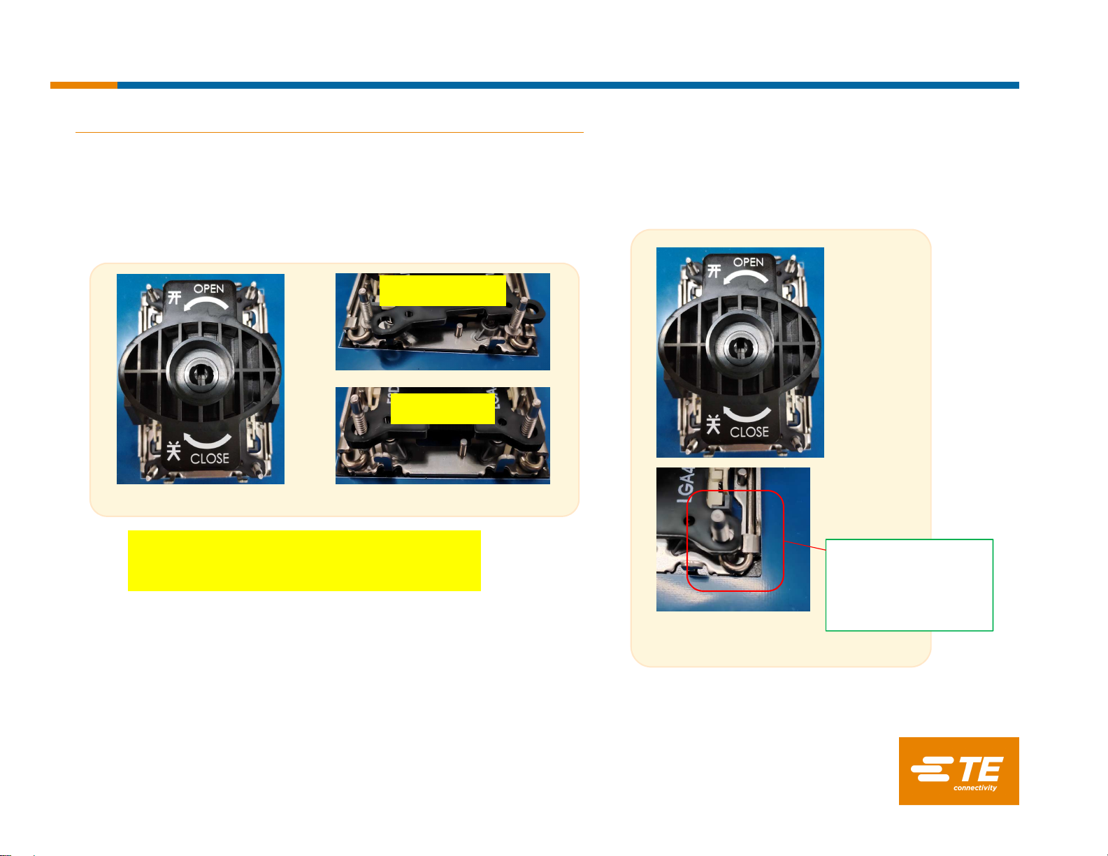
3.3 Assemble bolster plate on PCB
Attach bolster plate on PCB top side. gasket side down, on the board
Holding bolster plate to maintain alignment, fully fasten nut#1 first with 0.904N.m(8in-lbf) of torque.
Tighten the nuts in any order
Tool: Electric torque
T-20 Torx bit
Torque:0.904N.m or
8 in-ibf
IMPORTANT: Tighten the nuts in any order.
Fig.5
6
Instruction Sheet
411-115008 Rev.A
20th Mar’20
TE Connectivity Confidential & Proprietary. Do not reproduce or distribute.
7
3. Attachment hardwareAssy and back plate Assy procedure
3.4.1 Pick & Place cover removal
Instruction Sheet
411-115008 Rev.A
20th Mar’20
TE Connectivity Confidential & Proprietary. Do not reproduce or distribute.
8
3. Attachment hardwareAssy and back plate Assy procedure
3.4.2 Pick & Place cover removal
Gently engage the PnP tool with bolster plate assembly ensuring the corner alignment features sit
on PnP covers evenly.
X
√
IN-CORRECT
CORRECT
NOTE: PnP removal tool has four alignment tabs with
holes that engage with the bolster plate assembly
studs. PnP PnP removal tool
alignment tab
correctly placed on
Bolster plate stud
Instruction Sheet
411-115008 Rev.A
20th Mar’20
TE Connectivity Confidential & Proprietary. Do not reproduce or distribute.
9
3. Attachment hardwareAssy and back plate Assy procedure
3.4.3 Pick & Place cover removal
Gently hold the tool down and rotate the knob clockwise 90 degrees until it is in the closed position
releasing the PnP Covers.
Slowly lift the tool up vertically. Make sure both PnP covers are securely latched in the tool. Use caution
to not touch socket contacts. Use caution to not touch socket contacts.
Instruction Sheet
411-115008 Rev.A
20th Mar’20
TE Connectivity Confidential & Proprietary. Do not reproduce or distribute.
10
3. Attachment hardwareAssy and back plate Assy procedure
3.4.4 Pick & Place cover removal
Once a tool and PnP covers are away from the board, rotate the knob of the tool counter-clockwise
90 degrees to release PnP covers.
Instruction Sheet
411-115008 Rev.A
20th Mar’20
TE Connectivity Confidential & Proprietary. Do not reproduce or distribute.
11
3. Attachment hardwareAssy and back plate Assy procedure
3.5 Dust Cover Assembly to Socket
Once PnP covers are removed from the socket, carefully engage the dust cover vertically to the
bolster plate assembly posts over the socket.
Instruction Sheet
411-115008 Rev.A
20th Mar’20
TE Connectivity Confidential & Proprietary. Do not reproduce or distribute.
12
4. Processor Heat sink Module (PHM) Sub-Assemblyfor Factory and Field Replaceable Unit (FRU)
4.1 Material
Instruction Sheet
411-115008 Rev.A
20th Mar’20
TE Connectivity Confidential & Proprietary. Do not reproduce or distribute.
13
4. Processor Heat sink Module (PHM) Sub-Assemblyfor Factory and Field Replaceable Unit (FRU)
4.2.1 Caution & Processor Handling
Instruction Sheet
411-115008 Rev.A
20th Mar’20
TE Connectivity Confidential & Proprietary. Do not reproduce or distribute.
14
4. Processor Heat sink Module (PHM) Sub-Assemblyfor Factory and Field Replaceable Unit (FRU)
4.2.2 Processor Carrier Assembly
Place the processor carrier on top of the processor that is in the package tray aligning pin 1 marks on the
processor carrier to pin 1 of the processor.
Note: Make sure that the keying feature tabs of the processor carrier are aligned to the slots in the processor properly. If
not check that the correct processor carrier is being used.
TE Connectivity Confidential & Proprietary. Do not reproduce or distribute.
15
4. Processor Heat sink Module (PHM) Sub-Assembly for Factory and Field Replaceable Unit (FRU)
4.2.3 Processor Carrier Assembly
Using two fingers, while aligning the package with Processor carrier, press down on the Processor carrier
at the opposite end of the TIM break lever until a snap sound is heard.
Using two fingers press down on the Processor carrier at the end of the TIM break lever until a snap sound is heard.
Check the two side snap latches on the carrier and verify that they have latched to the package. If not then press down
on top of the side snap latches until they snap into place.
Instruction Sheet
411-115008 Rev.A
20th Mar’20
TE Connectivity Confidential & Proprietary. Do not reproduce or distribute.
16
4. Processor Heat sink Module (PHM) Sub-Assembly for Factory and Field Replaceable Unit (FRU)
4.2.4 Processor Carrier Assembly Inspection
Verify that the processor is securely latched to the processor carrier. The processor carrier should be flat
and level to the processor top. If the processor carrier is not latched properly, press the processor carrier
down as outlined in section 4.2.3.
Instruction Sheet
411-115008 Rev.A
20th Mar’20
TE Connectivity Confidential & Proprietary. Do not reproduce or distribute.
17
4. Processor Heat sink Module (PHM) Sub-Assemblyfor Factory and Field Replaceable Unit (FRU)
4.3.1 Processor Carrier Assembly to Heatsink
If there is TIM (Thermal Interface Material) protective film on the base of heatsink, remove it.
Turn the heatsink over and set the Anti-Tilt wires to the locked position (outward position).
Instruction Sheet
411-115008 Rev.A
20th Mar’20
TE Connectivity Confidential & Proprietary. Do not reproduce or distribute.
18
4. Processor Heat sink Module (PHM) Sub-Assemblyfor Factory and Field Replaceable Unit (FRU)
4.3.2 Processor Carrier Assembly to Heatsink
Align Pin 1 indicator of Processor carrier and the corner cut out of Heatsink. If there are two corners cut
out, either orientation is fine.
Place the heatsink ensure latching features on Processor carrier and heatsink are aligned during assembly.
Instruction Sheet
411-115008 Rev.A
20th Mar’20
TE Connectivity Confidential & Proprietary. Do not reproduce or distribute.
19
4. Processor Heat sink Module (PHM) Sub-Assemblyfor Factory and Field Replaceable Unit (FRU)
4.3.3 Processor Carrier Assembly to Heatsink
Press heatsink down firmly to engage carrier latching features to the heatsink at four corners. Check if the
processor is assembled with processor carrier properly. If not, reassemble the processor into processor carrier.
If carrier latching features do not latch the heatsink properly, engage each latching features by pressing the heatsink at
the unlatched corner. You may hear a clicking sound when latched.
Instruction Sheet
411-115008 Rev.A
20th Mar’20
TE Connectivity Confidential & Proprietary. Do not reproduce or distribute.
20
4. Processor Heat sink Module (PHM) Sub-Assemblyfor Factory and Field Replaceable Unit (FRU)
4.3.4 PHM Assembly Inspection
Verify that the carrier is properly latched to the heatsink at all four corners. If not, attach the carrier
assembly to the heatsink by following section 4.3.3.
Instruction Sheet
411-115008 Rev.A
20th Mar’20

Other TE Connectivity Accessories manuals

TE Connectivity AST20PT User manual

TE Connectivity

TE Connectivity AST20PT User manual

TE Connectivity EV Charge Inlet Combo 2 User manual

TE Connectivity

TE Connectivity EV Charge Inlet Combo 2 User manual

TE Connectivity LGA1366 User manual

TE Connectivity

TE Connectivity LGA1366 User manual

Popular Accessories manuals by other brands

Dialogic Analog Telecom Board D/120JCT-LSU installation guide

Dialogic

Dialogic Analog Telecom Board D/120JCT-LSU installation guide

Omron ZS Command reference guide

Omron

Omron ZS Command reference guide

Philips HD7003 Specifications

Philips

Philips HD7003 Specifications

Flame mQMCV manual

Flame

Flame mQMCV manual

Maclean Energy MCE359 manual

Maclean Energy

Maclean Energy MCE359 manual

Vicks VH1800EU user manual

Vicks

Vicks VH1800EU user manual

PNJ G-SKY100 user manual

PNJ

PNJ G-SKY100 user manual

dol sensors DOL 25  NPN DOL Technical user guide

dol sensors

dol sensors DOL 25 NPN DOL Technical user guide

Takex FS-1000E instruction manual

Takex

Takex FS-1000E instruction manual

PowerTech MB3830 instruction manual

PowerTech

PowerTech MB3830 instruction manual

Dodge SCXT 305E instruction manual

Dodge

Dodge SCXT 305E instruction manual

PCB Piezotronics IMI SENSORS 641B61 Installation and operating manual

PCB Piezotronics

PCB Piezotronics IMI SENSORS 641B61 Installation and operating manual

LEGRAND Wattstopper LMPW-101 quick start guide

LEGRAND

LEGRAND Wattstopper LMPW-101 quick start guide

Air Creative Classic Line 925 installation guide

Air Creative

Air Creative Classic Line 925 installation guide

Superfly SUPERX8 user manual

Superfly

Superfly SUPERX8 user manual

Wire wizard HHSS instruction manual

Wire wizard

Wire wizard HHSS instruction manual

EMX Industries RAVEN quick start guide

EMX Industries

EMX Industries RAVEN quick start guide

Baltimore Aircoil Company 3000 Series Operating and maintenance instructions

Baltimore Aircoil Company

Baltimore Aircoil Company 3000 Series Operating and maintenance instructions

manuals.online logo
manuals.online logoBrands
  • About & Mission
  • Contact us
  • Privacy Policy
  • Terms and Conditions

Copyright 2025 Manuals.Online. All Rights Reserved.