TE Connectivity 2098627 User manual

1 of 5
© 2014 TE Connectivity family of companies
All Rights Reserved
*Trademark
TE Connectivity, TE connectivity (logo), and TE (logo) are trademarks. Other logos, product, and/or company names may be trademarks of their respective owners.
TOOLING ASSISTANCE CENTER
1-800-722-1111
PRODUCT INFORMATION
1-800-522-6752
This controlled document is subject to change.
For latest revision and Regional Customer Service,
visit our website at www.te.com.
Instruction Sheet
408-32154
18 NOV 14 Rev A
Not available from TE Connectivity—1.5-mm are manufactured by Molex; 2.8- and 6.3-mm are manufactured by Delphi.
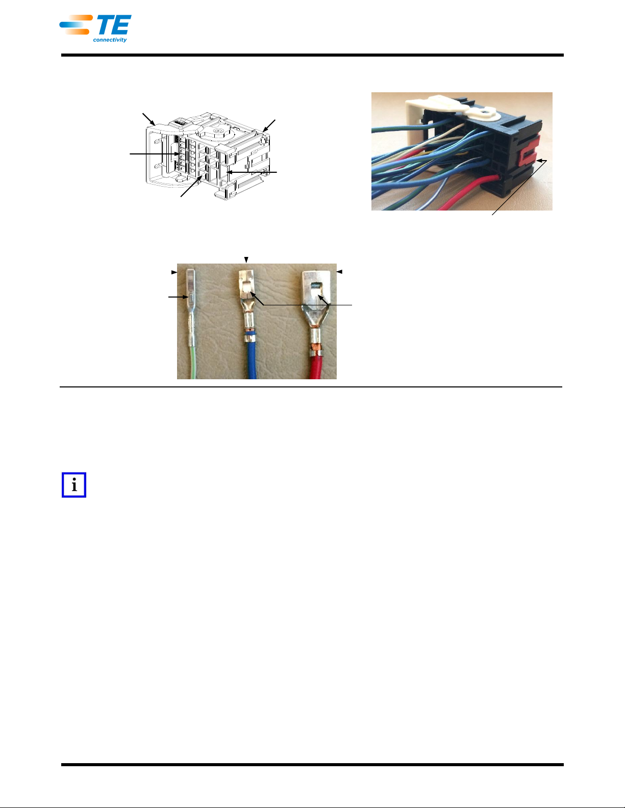
Figure 1
Plug assembly features are given in Figure 1. Contacts and a wire dress cover, both available separately, are
required for assembly. Contact description and wire dress cover part numbers and features are given in Figure 1.
1. ASSEMBLY
1.1. Insert Contacts
1. Ensure that the TPA and rotating locking lever are each in the open (unlocked) position. Refer to
Figure 1. If either are not in the open (unlocked) position, refer to Paragraphs 2.1 (TPA) and 2.3
(rotating locking lever).
2. Crimp the contacts according to instructions provided by the manufacturer.
3. Select the plug housing contact cavities to be loaded with contacts. Refer to the table in Figure 1.
4. From the wire end of the plug, align each crimped contact with the applicable contact cavity as
described in Figure 2, Detail A. Grasp the wire of the contact and insert the contact straight into the
contact cavity. See Figure 2, Detail B. The retention latch finger of the contact cavity will be deflected
by the contact and hold it in place.
5. Lightly pull each wire to ensure that the retention latch finger is holding the contact in place.
Automotive Unsealed Hybrid
Plug Assemblies 2098627-[ ] (22 Positions)
and 2138731-[ ] (36 Positions)
Terminal Position Assurance
(TPA) in Open (Unlocked)
Position (Protrudes Slightly
from Bottom of Housing)
Hybrid Plug Assembly
(22-Position Shown)
90-Degree Wire Dress Cover
(22-Position Shown)
PLUG
ASSEMBLY
POSITIONS
CONTACTS
WIRE DRESS
COVER
Type
Amount (Contact Cavity)
2098627-[ ] 22
1.5-mm
12 (Small)
2098628-1
2.8-mm
07 (Medium)
6.3-mm
03 (Large)
2138731-[ ] 36
1.5-mm
20 (Small)
2098622-1
2.8-mm
10 (Medium)
6.3-mm
06 (Large)
Rotating Locking Lever
in Open (Unlocked)
(Horizontal) Position
Housing
Contact Cavities
Mating Face
Lever Locking
Latch
Retention Tab
(2 Places)
Wire Exit
Locking
Beam
Molex and Delphi are trademarks of their respective owners.
408-32154
Rev A
2 of 5
Figure 2
1.2. Move TPA to Locked Position
The TPA must be moved to the closed (locked) position after all contacts have been inserted. Push the TPA
evenly into the plug housing until it is flush with the bottom of the housing. See Figure 2, Detail B.
NOTE
If the TPA does not move easily into the closed (locked) position, one or more of the contacts are not fully inserted. Move the
TPA to the open (unlocked) position (refer to Paragraph 2.3), and check that all contacts are fully inserted.
1.3. Install Wire Dress Cover
The wire dress cover must be installed onto the plug housing after the TPA is moved to the closed (locked)
position.
1. Form a wire bundle, and move it toward the end of the housing opposite the rotating locking lever.
2. Align the bottom of the wire dress cover with the wire end of the housing so that the wire exit is over
the wire bundle. Then, position the retention tabs of the wire dress cover into the retention slots of the
housing. See Figure 3, Detail A.
3. Ensure that the wire bundle is completely captured within the wire dress cover and no wires are
pinched between the housing and the wire dress cover, then push the wire dress cover onto the
housing until both ends of the wire dress cover lock into place. There will be an audible and tactile
click. See Figure 3, Detail B.
4. Using tape or cable ties, secure the wire bundle to the wire dress cover.
Rotating Locking Lever in
Open (Unlocked) Position
Detail A—Aligning Contacts with Contact Cavity
1.5-mm Contacts (Small)
Align Orientation Tab with
Top of Contact Cavity
Small
Contact Cavities
Medium
Contact Cavities
Large
Contact Cavities
Wire End of Plug
TPA in Open
(Unlocked) Position
6.3-mm Contacts (Large)
Detail B—Contacts Installed in Contact Cavity
TPA in Closed
(Locked) Position
2.8-mm Contacts (Medium)
Contact Orientation
Align Locking Window with
Top or Bottom of Contact Cavity
408-32154
Rev A
3 of 5
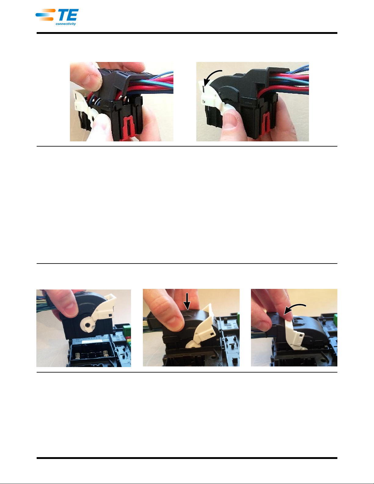
Figure 3
1.4. Mate Plug with Interface Assembly
The wire dress cover must be installed before the plug can be mated to the interface assembly.
1. Ensure that the rotating locking lever of the plug is in the open (unlocked) (horizontal) position as
shown in Figure 4, Detail A .
2. Align the mating face of the plug with the mating face of the interface assembly, ensuring that the keys
are mutually oriented, then insert the plug into the interface assembly until it bottoms. The rotating
locking lever will rotate approximately 15° as shown in Figure 4, Detail B. There will be an audible and
tactile click. The plug rotating locking lever in now in the pre-locked position.
3. Move the rotating locking lever until it latches onto the lever locking latch of the wire dress cover.
There will be an audible and tactile click. The plug rotating locking lever is now in the closed (locked)
(vertical) position. See Figure 4, Detail C.
Figure 4
2. DISASSEMBLY
2.1. Unmate Plug
1. Press the lever locking latch of the wire dress cover. See Figure 5, Detail A.
2. Rotate the rotating locking lever over the lever locking latch until it cannot be rotated any further. The
rotating locking lever is now in the open (unlocked) (horizontal) position. See Figure 5, Detail B.
3. Pull the plug straight away from the interface assembly. See Figure 5, Detail C.
Installing Wire Dress Cover onto Plug
Detail A
Detail B
Detail A
Detail B
Detail C
Mating Plug to Interface Assembly
408-32154
Rev A
4 of 5
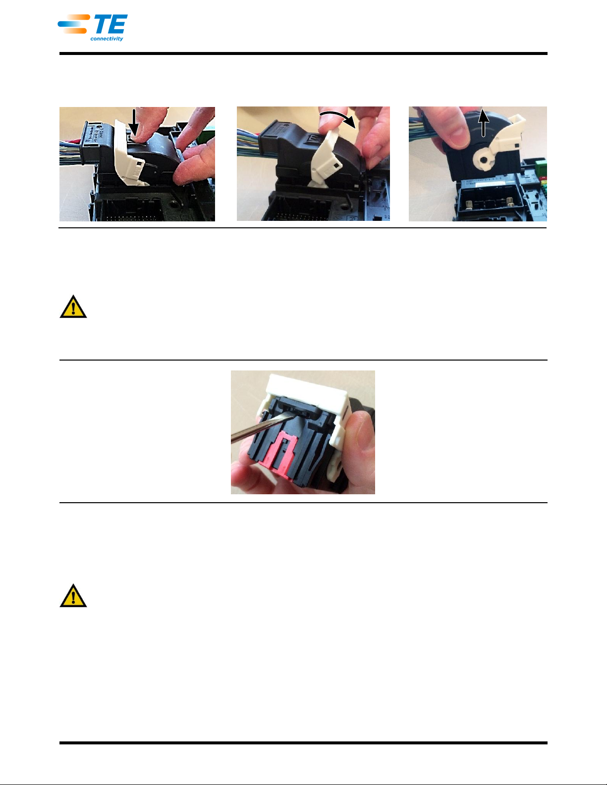
Figure 5
2.2. Remove Wire Dress Cover
1. If present, remove any tape or cable ties from the wire bundle.
CAUTION
Be careful not to nick or cut the wire insulation.
2. Using a jeweler’s screwdriver, carefully depress the locking beam of the wire dress cover, and pull the
wire dress cover from the plug housing. See Figure 6.
Figure 6
2.3. Move TPA to Open (Unlocked) Position
Using a jeweler’s screwdriver, lift the bottom of each latch of the TPA until it disengages from the housing, then
gently pull the TPA so that it protrudes slightly from the bottom of the plug housing. See Figure 7.
CAUTION
Do not force the TPA when pulling it; otherwise, it will separate from the plug housing and must be re-installed.
Detail A
Detail B
Detail C
Unmating Plug from Interface Assembly
408-32154
Rev A
5 of 5
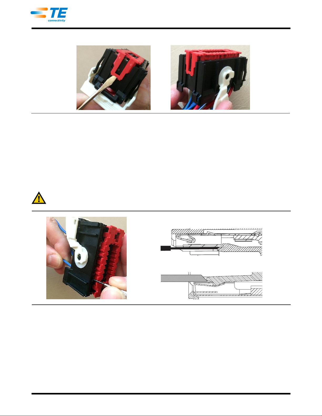
Figure 7
2.4. Remove Contacts
The wire dress cover must be removed and the TPA must be moved to the open (unlocked) position before any
contacts can be removed.
1. From the mating face of the plug, insert the tip of a jeweler’s screwdriver into the contact cavity of the
contact to be removed until it stops, then rotate the screwdriver toward the contact to deflect the
retention latch finger of the contact cavity.
2. Holding the screwdriver tool in place, gently pull the wire of the contact to be removed until the contact
is out of the housing. See Figure 8.
CAUTION
Take care not to damage the contacts during removal.
Figure 8
3. REPLACEMENT AND REPAIR
Do not used damaged or defective product. The plug, wire dress cover, and contacts are not repairable. Do not
re-use contacts by removing the wire.
4. REVISION SUMMARY
Initial release of instruction sheet
Moving TPA to Open (Unlocked) Position
Removing 1.5-mm Contact
Removing 2.8-mm or 6.3-mm Contact
This manual suits for next models
1
Table of contents


