TE 59239-4 User manual

Instruction Sheet
1 of 19
© 2023 TE Connectivity Ltd. family of companies.
All Rights Reserved.
TE Connectivity, TE connectivity (logo), and TE (logo) are trademarks. Other logos, product, and/or company names may be trademarks of their respective owners.
PRODUCT INFORMATION
1-800-522-6752
This controlled document is subject to change.
For latest revision and Regional Customer Service,
visit our website at www.te.com.
408-1261
28 FEB 2023 Rev L
Proper use guidelines
Cumulative trauma disorders can result from the prolonged use of manually powered hand tools. Hand tools are intended for occasional
use and low-volume applications. A wide selection of powered application equipment is available for extended-use production operations.
Figure 1: Heavy Head Hand Tools 59239-4, 59239-8, 59287-2, and 525692
1
304.8 [12.00] approximate
2
76.2 [3.00] approximate
1 Introduction
Heavy Head Hand Tools (HHHT) 525692, 59239-4, 59239-8, and 59287-2 are the tool and die set shown in
Figure 1. These tools are designed to crimp the product listed in Table 1 onto the wire also listed.
For other tools accompanied by this instruction sheet, follow the instructions for the tool used to crimp the same
wire size.
NOTE
Dimensions in this instruction sheet are in millimeters with [inches in brackets]. Figures are for reference only and are not
drawn to scale.
Read these instructions thoroughly before crimping connectors.
Heavy Head Hand Tools 59239-4, 59239-8,
59287-2, and 525692

408-1261
Rev L
2 of 19
Table 1: Crimping specifications
Tool
Product
Wire
Type
Insulation color code
Type
Size (AWG)
Insulation diameter
mm [in.]
59239-4
59239-8
525692
PIDG™vinyl and
nylon terminal
PIDG vinyl and
nylon splice
PLASTI-GRIP™terminal
Yellow
Solid or
stranded
copper
12-10
5.84-6.35 [.230-.250]
Yellow with black stripes
16-14
(heavy duty)
PIDG insulation restring
nylon terminal
Yellow with 3 yellow
stripes
Stranded
copper
12
2.41-5.08 [.095-.200]
Yellow with 3 brown
stripes
10
3.02-5.08 [.119-200]
PIDG radiation resistant
terminal and splice
Natural with yellow stripe
Stranded
copper
12-10
6.60 [.260] maximum
16-14
(heavy duty)
Spare wire cap 328309
Yellow
Stranded
copper
12-10
5.33 [.210] maximum
59287-2
PIDG vinyl and
nylon terminal
PIDG vinyl and
nylon splice
PLASTI-GRIP terminal
Yellow
Solid or
stranded
copper
12-10
6.99-7.62 [.275-.300]
Yellow with black stripe
16-14
(heavy duty)
408-1261
Rev L
3 of 19
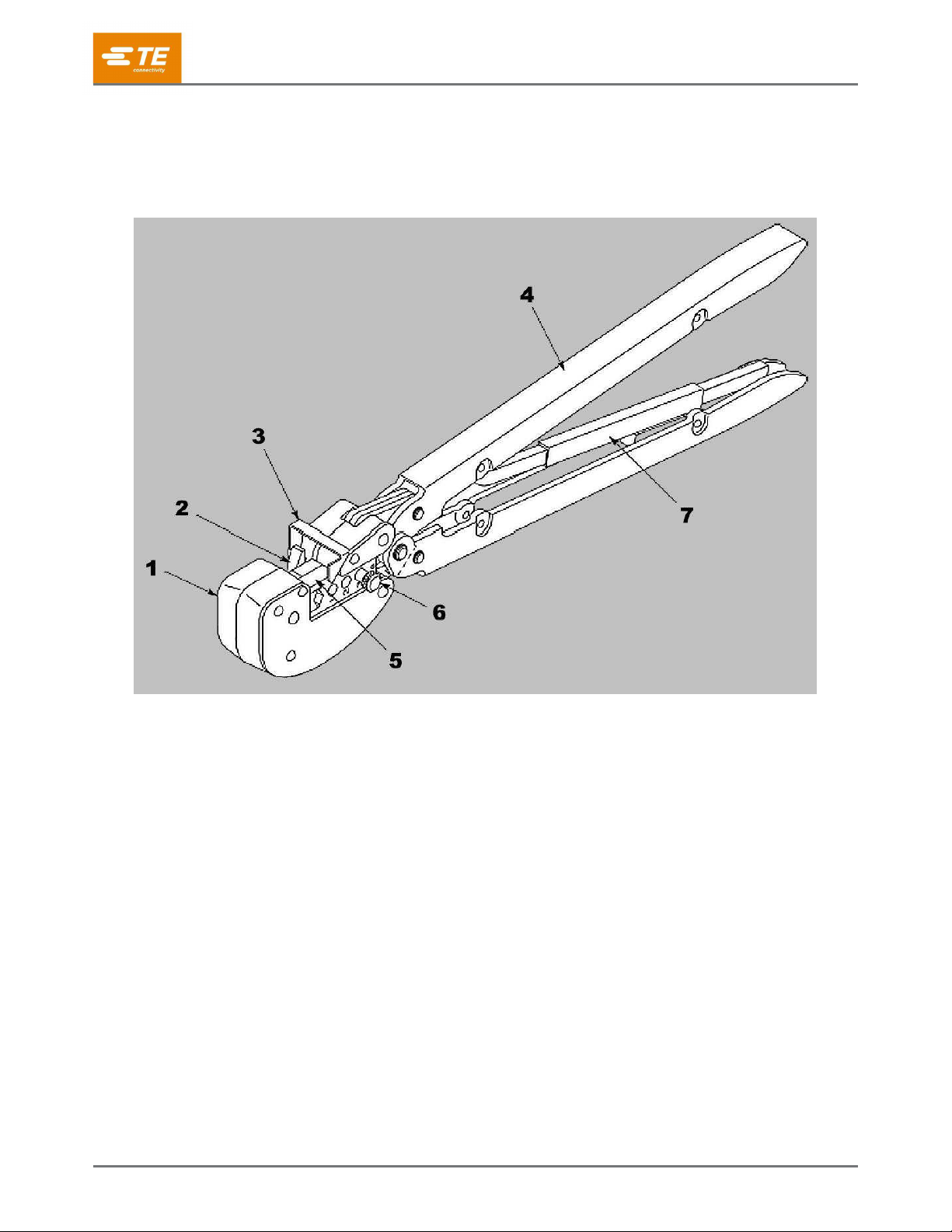
2 Description
Each tool consists of a head containing two stationary crimping dies (anvils), two movable crimping dies
(indenters), a locator, an insulation crimping adjustment pin, and handles with a ratchet. See Figure 2.
Figure 2: Tool components
1
Head
5
Movable crimping dies (indenters)
2
Stationary crimping dies (anvils)
6
Insulation crimping adjustment pin
3
Locator
7
Ratchet
4
Handle
These tools are members of the CERTI-CRIMP™hand crimping tool family. The ratchet on these tools ensures
full crimping of the product. After it is engaged, the ratchet does not release until the handles have been fully
closed.
When closed, the crimping dies form a crimping chamber with two sections: an insulation barrel section and a
wire barrel section. The insulation barrel section crimps the insulation barrel of the product onto the wire
insulation. Simultaneously, the wire barrel section crimps the wire barrel of the product onto the wire
conductors.
The crimping dies bottom before the ratchet releases. This design ensures maximum electrical and tensile
performance of the crimp. Do not re-adjust the ratchet.
The locator positions the product in the crimping chamber. The insulation crimping adjustment pin is used to
regulate the height of the insulation crimp.

408-1261
Rev L
4 of 19
Tool handles are colored yellow to correspond to the color code of the product. Each tool produces a dot code
(one dot) on the crimp to correspond to the given wire size range. Refer to Figure 3.
Figure 3: Product color code
1
PIDG terminals
2
PLASTI-GRIP terminal
3
PIDG butt splice
4
Spare wire cap
5
Color stripe on heavy duty and radiation resistant
6
Three equally space color stripes on insulation restricting
7
Color stripe on heavy duty
8
Color stripe on radiation resistant
9
Color of insulation

408-1261
Rev L
5 of 19
3 Crimping
Make sure that the insulation color code of the product matches the color of the tool handles (see Figure 3).
3.1 Stripping the wire
Strip the wire within the dimensions listed in Table 2. Do not nick or damage the wire conductors.
CAUTION
Do not use wire with nicked or missing conductors.
Figure 4: Wire strip length
Table 2: Strip length by product
Product
Strip length
PIDG vinyl and nylon terminal
PLASTI-GRIP terminal
PIDG radiation resistant terminal
7.94-8.73 [.312-.344]
PIDG insulation restricting nylon terminal
9.65-10.4 [.380-.410]
PIDG vinyl and nylon splice
PIDG radiation resistant splice
Spare wire cap
8.64-9.65 [.340-.380]
408-1261
Rev L
6 of 19
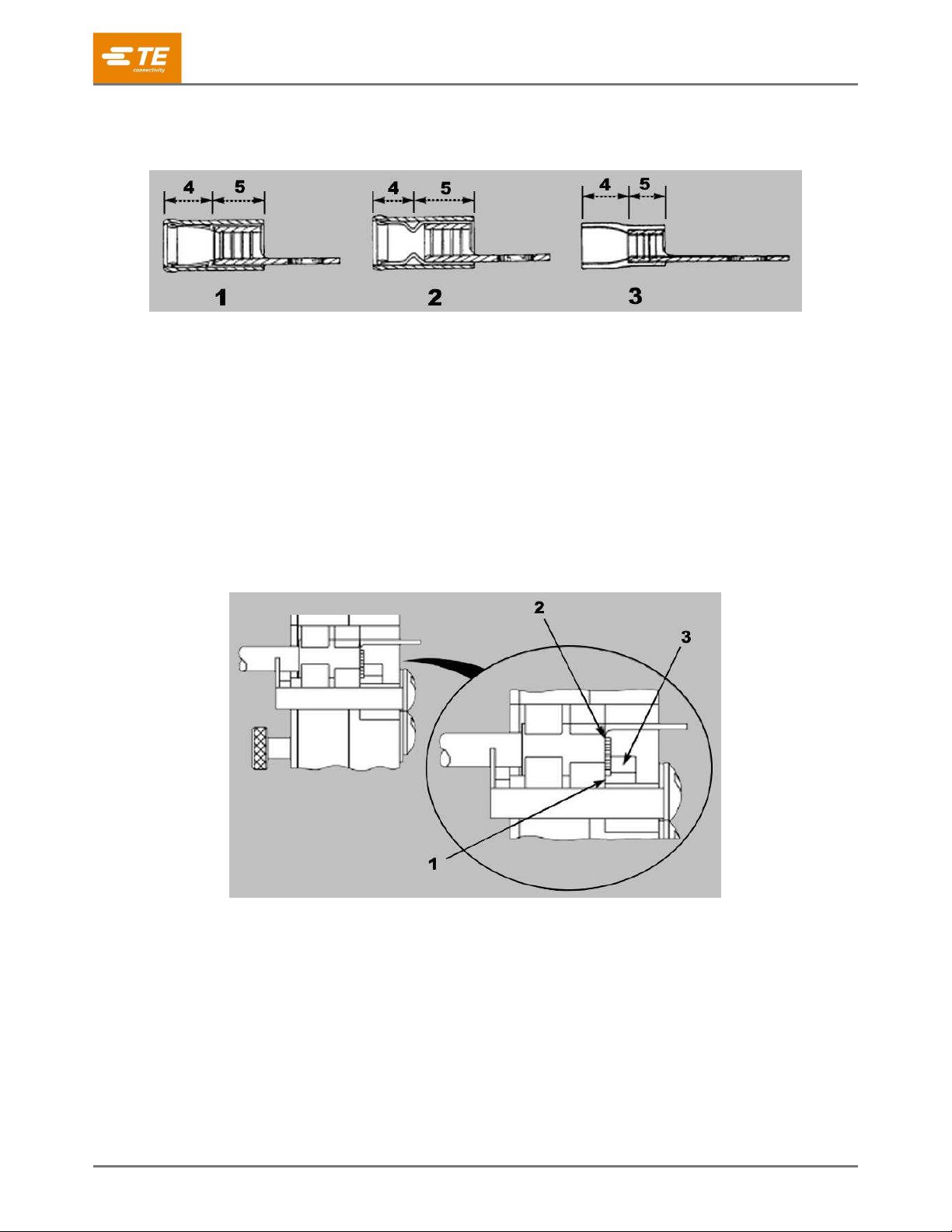
3.2 Crimping a terminal
Figure 5: Terminal types
1
PIDG terminal
2
PIDG insulation-restricting terminal
3
PLASTI-GRIP terminal
4
Insulation barrel
5
Wire barrel
To crimp a terminal, complete the following steps.
1. Insert the insulation crimp adjustment pin in the proper position as described in section 4.
2. Open the crimping dies by closing the tool handles until the ratchet releases, then allow the handles to
open fully.
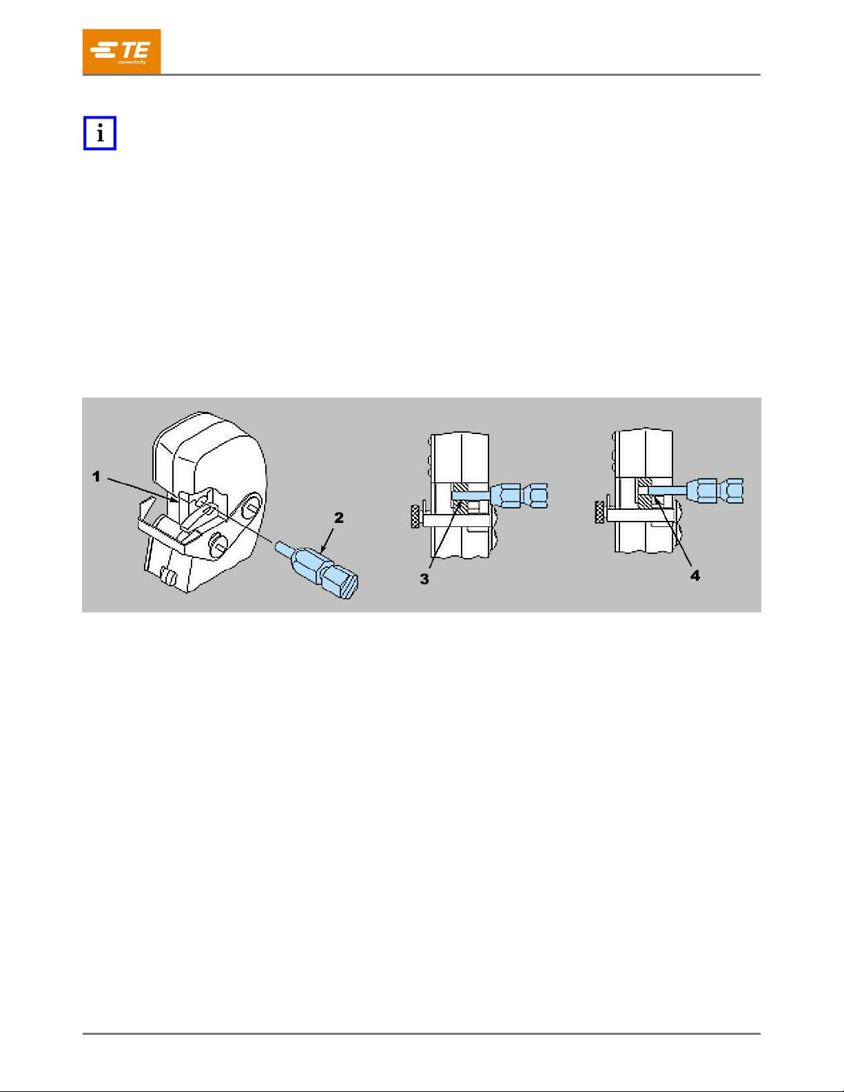
3. Place the terminal in the crimping chamber so that the wire barrel butts against the locator (Figure 6).
Figure 6: Positioning the terminal
1
Wire barrel against locator
2
End of wire conductors against locator
3
Locator
4. Close the tool handles until the terminal is held firmly in place. Do not deform the terminal.
5. Insert a properly stripped wire into the terminal wire barrel until the end of the wire conductor(s) butts
against the locator.
6. Complete the crimp by closing the tool handles until the ratchet releases.
7. Release the tool handles, allow the handles to open fully, and remove the crimped terminal.
8. Inspect the crimp as described in sections 4.1 and 4.3. Do not use terminals that fail to meet the
required conditions.
408-1261
Rev L
7 of 19
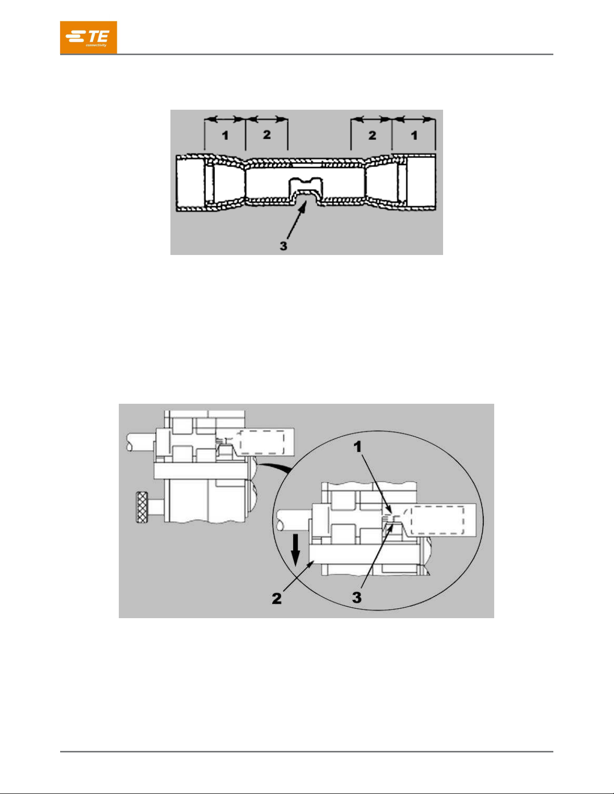
3.3 Crimping a butt splice
Figure 7: Butt splice
1
Insulation barrel
2
Wire barrel
3
Window indentation
To crimp a butt splice, complete the following steps.
1. Open the crimping dies by closing the tool handles until the ratchet releases, then allow the handles to
open fully.
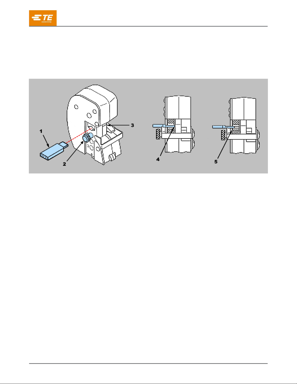
2. Depress the locator. Position the splice in the crimping chamber so that window indentation of the
splice rests over the locator (Figure 8).
Figure 8: Positioning the butt splice
1
End of wire conductors against splice wire stop
2
Locator depressed
3
Splice window indentation over locator
3. Close the tool handles until the splice is held firmly in place. Do not deform the splice.
4. Insert a properly stripped wire into the wire barrel of the splice until the end of the wire conductor butts
against the splice wire stop.
5. Complete the crimp by closing the tool handles until the ratchet releases.
408-1261
Rev L
8 of 19
6. Release the tool handles and allow the handles to open fully.
7. Remove the crimped splice.
8. Turn the splice around, depress the locator, and position the splice in the crimping chamber so that the
window indent of the splice seats over the locator. Follow steps 3 through 6.
9. Inspect the crimp as described in section 4.2. Do not use splices that fail to meet the required
conditions.
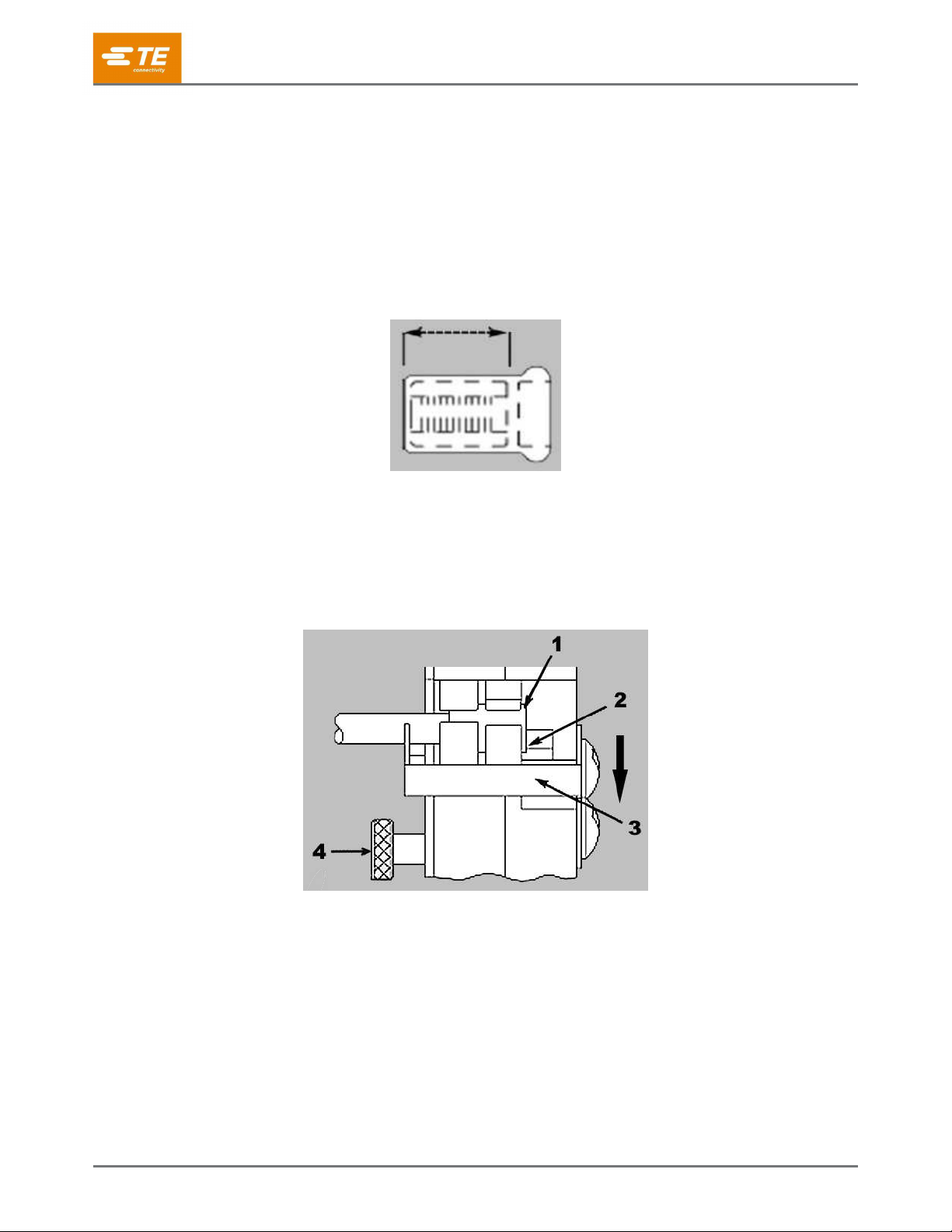
3.4 Crimping a spare wire cap
Figure 9: Wire barrel of spare wire cap
1. Place the tool insulation adjustment pins in the position 3.
2. Close the tool handles until the crimping dies partially close, but leave enough space for the spare wire
cap to be inserted in the crimping chamber.
3. Depress the locator so that the end of the spare wire cap rests against the recessed surface of the
locator (Figure 10).
Figure 10: Positioning the spare wire cap
1
Wire conductors bottomed in spare wire cap
2
End of spare wire cap against recessed surface of locator
3
Locator depressed
4
Insulation pin in position 3
4. Close the tool handles until the spare wire cap is held firmly in place. Do not deform the spare wire
cap.
5. Insert a properly stripped wire into the spare wire cap until the wire conductor(s) bottoms.
6. Hold the wire in position, and complete the crimp by closing the tool handles until the ratchet releases.
7. Release the tool handles, allow the handles to open fully, and remove the crimped spare wire cap.
8. Inspect the crimp as described in section 4.4. Do not use caps that fail to meet the required conditions.

408-1261
Rev L
9 of 19
4 Inspecting the crimp
4.1 PIDG or PLASTI-GRIP terminal
Inspect the crimp for the features shown in Figure 11. Do not use a terminal that has any of the features shown
in Figure 12.
Figure 11: Features of a good crimp (terminal)
1
Insulation barrel is in firm contact with wire insulation
2
Correct color code, dot code, and tool combination
3
Crimp is centered on wire barrel
4
End of conductor is flush with (or extends beyond) end of terminal wire barrel
5
Wire size is within range stamped under terminal tongue
6
Dot code (one dot) is present
7
Wire insulation does not enter wire barrel
8
No nicked or missing conductor strands
9
End of conductor butts against wire stop
Figure 12: Features of a poor crimp (terminal)
1
Nicked or missing conductor strands
2
Crimp not centered on wire barrel (terminal was not against locator)
3
End of conductor not flush with (or extending beyond) end of terminal wire barrel (check strip length)
4
Wire insulation is extruded (insulation crimp is too tight)
5
Wrong color code and dot code combination
6
Excess flash or extruded insulation (wrong tool or terminal, or damaged dies)
7
Wire range stamped here
8
Wire insulation enters wire barrel
408-1261
Rev L
10 of 19
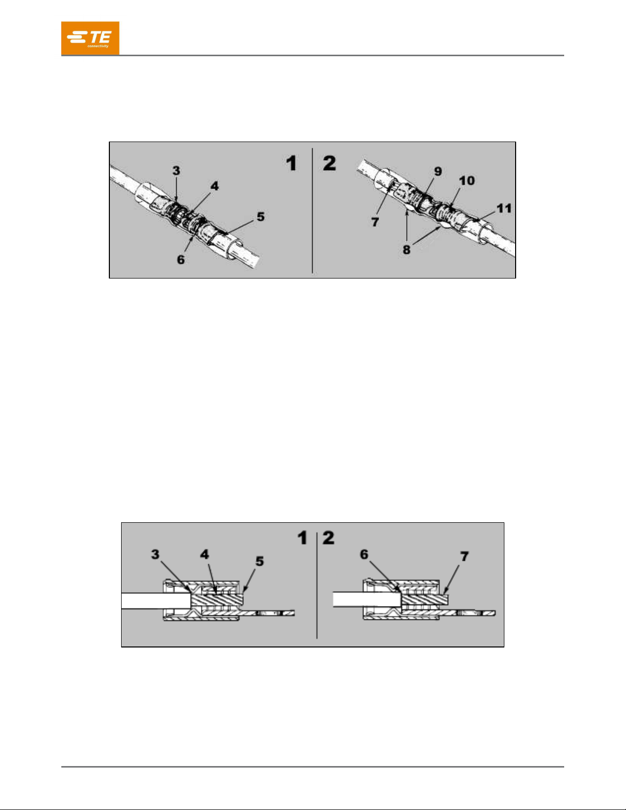
4.2 PIDG butt splice
For a PIDG butt splice, inspect the crimp for the features shown in Figure 13. Do not use a splice that has any
of the features of a poor crimp.
Figure 13: Inspecting a butt splice
1
Features of a good crimp
2
Features of a poor crimp
3
Crimp is centered on wire barrel
4
End of conductor butts against wire stop
5
Insulation barrel is in firm contact with wire insulation
6
Correct color code, dot code, and tool combination
7
Nicked or missing conductor strands
8
Excess flash or extruded insulation (wrong tool or splice, or damaged dies)
9
End of conductor not flush with (or extending beyond) end of terminal wire barrel (check strip length)
10
Wrong color code and dot code combination
11
Wire insulation is extruded (insulation crimp is too tight)
4.3 PIDG insulation-restricting terminal
Inspect the crimp for the features shown in Figure 14. Do not use a terminal that has any of the features of a
poor crimp.
Figure 14: Inspecting a PIDG insulation-restricting terminal
1
Features of a good crimp
2
Features of a poor crimp
3
Wire insulation does not enter wire barrel
4
No nicked or missing conductor strands
5
Conductor can extend slightly beyond wire barrel
6
Wire insulation enters wire barrel
7
Nicked or missing conductor strands

408-1261
Rev L
11 of 19
4.4 Spare wire cap
Inspect the crimp for the features shown in Figure 15. Do not use a cap that has any of the features of a poor
crimp.
Figure 15: Inspecting a spare wire cap
1
Features of a good crimp
2
Features of a poor crimp
3
No flash or extruded insulation
4
Correct color code, dot code, and tool combination
5
Correct wire size
6
Full width of crimp is over wire barrel of cap
7
Wire insulation does not enter wire barrel
8
No nicked or missing conductor strands
9
End of conductor is bottomed in cap
10
Part of crimp is off end of wire barrel (cap was not bottomed in recess of locator)
11
Nicked or missing conductor strands
12
End of conductor is not bottomed in cap
13
Wrong wire size
14
Excess flash or extruded insulation (wrong tool or damaged dies)
15
Wrong color code and dot code combination
408-1261
Rev L
12 of 19
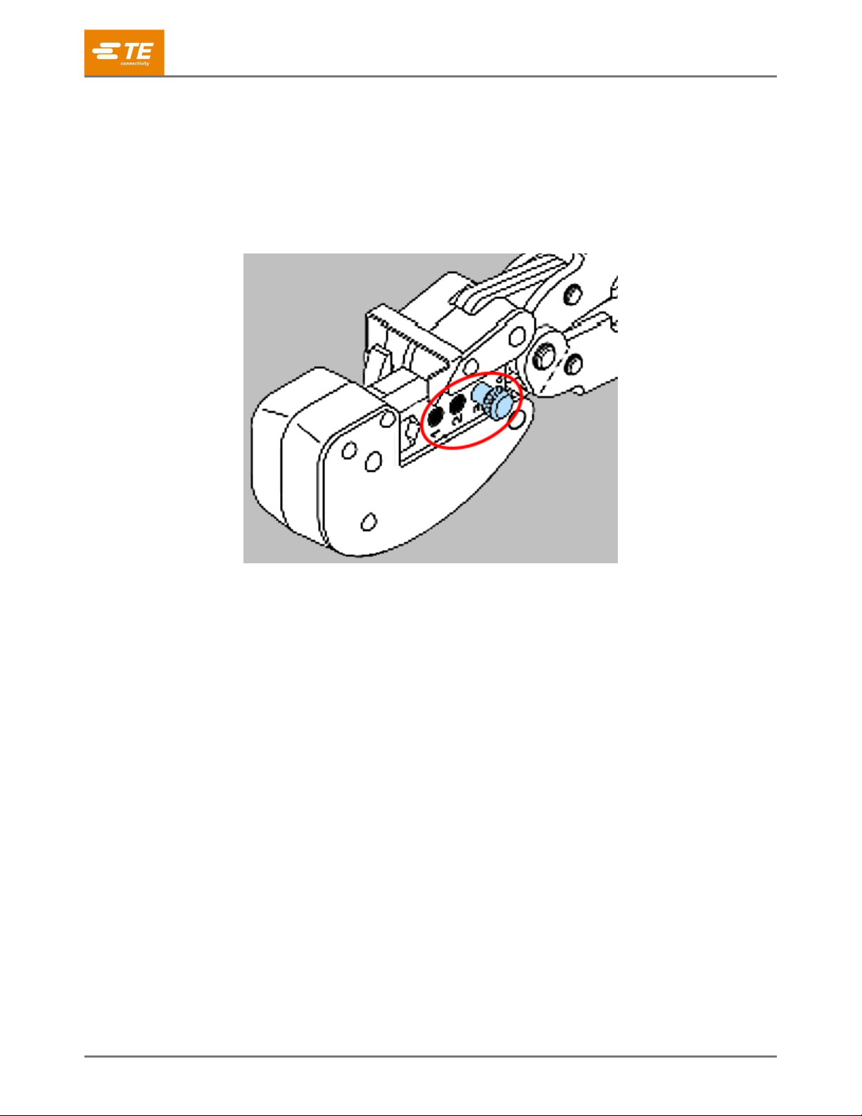
5 Adjusting the insulation crimp
The insulation crimping adjustment pin (Figure 16) has three positions:
1. Tight
2. Medium
3. Loose
Figure 16: Insulation crimping adjustment pin
To adjust the grip resulting from the crimp of the insulation barrel, proceed as follows.
5.1 PIDG terminal and splice
PIDG terminals and splices feature a wire insulation grip.
1. Insert the insulation crimp adjustment pin into position 3. Refer to Figure 1.
2. Place the terminal or splice into the crimping chamber as described in section 3.
3. Insert an unstripped wire into only the insulation barrel of the terminal or splice.
4. Close the tool handles until the ratchet releases.
5. Release the tool handles, and allow the handles to open fully. Remove the crimped terminal or splice.
6. Check the insulation barrel crimp by bending the wire back and forth once. The terminal or splice
should retain its grip on the wire insulation. If it does not, insert each insulation crimp adjustment pin
into the next position (position 2).
7. Repeat steps 2 through 6 until the correct insulation barrel grip is attained. Do not use a tighter position
than is necessary.
408-1261
Rev L
13 of 19
5.2 PLASTI-GRIP terminal
PLASTI-GRIP terminals and splices feature a wire insulation support only. Ideally, the terminal or splice
insulation should be in contact with the wire insulation.
Insert the insulation crimp adjustment pin into the appropriate position (see Table 3).
Table 3: Positions for the insulation crimp adjustment pins
Insulation diameter of wire
Pin position
Large
1
Medium
2
Small
3
6 Maintenance and inspection
6.1 Daily maintenance
Make each operator of the power unit aware of, and responsible for, the following daily maintenance
requirements:
Remove dust, moisture, and other contaminants with a clean, soft brush or soft, lint-free cloth. Do not
use objects that could damage the dies or tool.
Ensure that the retaining pins are in place and secured with retaining rings.
Protect all pins, pivot points, and bearing surfaces with a thin coat of any good SAE 20 motor oil. Do
not oil excessively.
When the tool is not in use, keep the handles closed to prevent objects from becoming lodged in the
dies.
Remove all lubrication and accumulated film by immersing the tool (with handles partially closed) in a
suitable commercial degreaser.
Store the tool in a clean, dry area.
6.2 Lubrication
Lubricate all pins, pivot points, and bearing surfaces with SAE 20 motor oil as indicated in Table 4.
Table 4: Lubrication schedule
How tool is used
When to lubricate
In daily production
Daily
Daily (occasional)
Weekly
Weekly
Monthly
Wipe excess oil from the tool, particularly from the crimping area. Oil transferred from the crimping area onto
terminations can affect the electrical characteristics of an application.

408-1261
Rev L
14 of 19
6.3 Periodic inspection
Regular inspections should be performed by quality control personnel. A record of scheduled inspections
should remain with the dies or be supplied to personnel responsible for the dies. Recommendations call for at
least one inspection per month. Base your inspection frequency on the amount of use, ambient working
conditions, operator training and skill, and established company standards. Perform the inspection as follows:
Close the tool handles until the ratchet releases and then allow them to open freely. If they do not open
quickly and fully, the spring is defective and must be replaced. Refer to section 7, Replacement and
repair.
NOTE
Some tools do not have handle return springs. This inspection does not apply to those tools.
Inspect the tool and dies on a regular basis to ensure that they are not worn or damaged.
Make sure that the die retaining screws are properly secured.
Inspect the crimping chambers of the die assembly for flattened, chipped, cracked, worn, or broken
areas.
If damage or abnormal wear is evident, return the tool for evaluation and repair. Refer to section 7,
Replacement and repair.
408-1261
Rev L
15 of 19
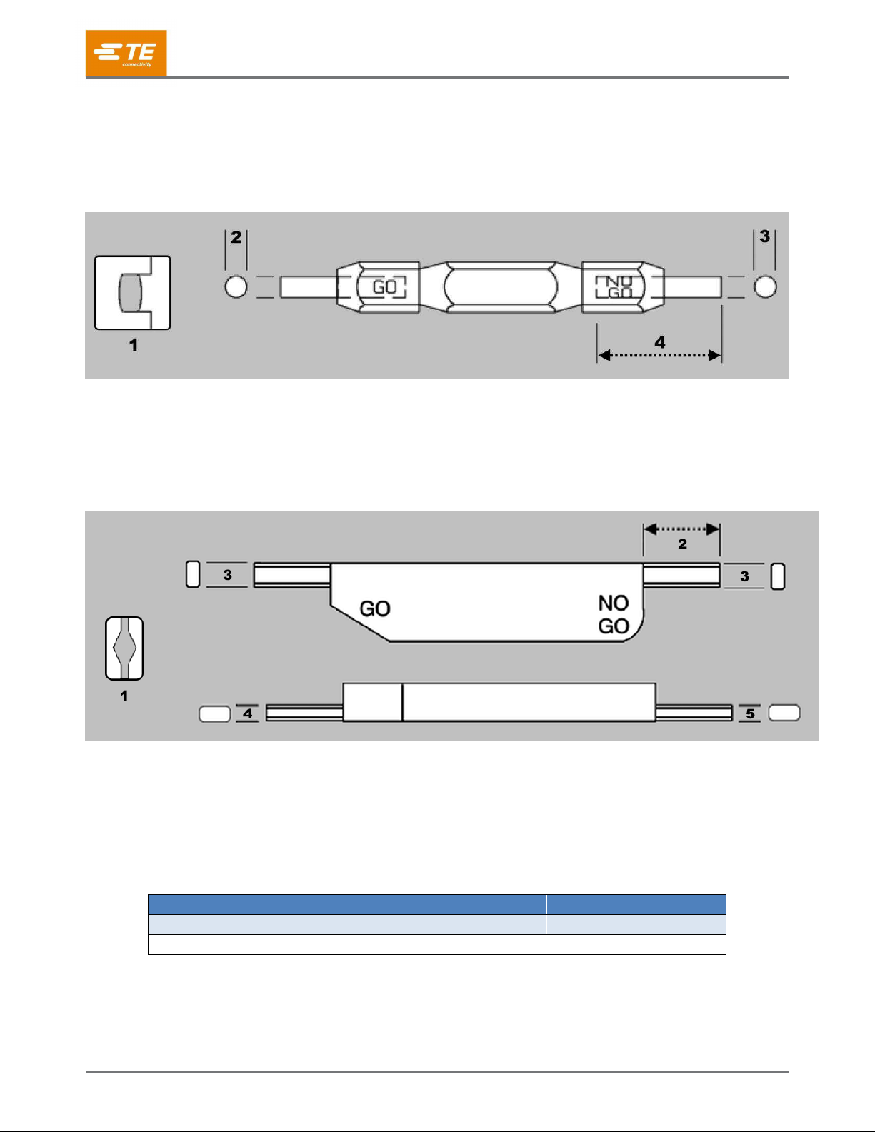
6.4 Gaging the crimping chamber
This inspection requires the use of plug gages conforming to the dimensions listed in Table 5. TE Connectivity
does not manufacture or market these gages. For additional information regarding the use of plug gages, refer
to instruction sheet 408-7424.
Figure 17: Recommended plug gage design for wire barrel section of crimping chamber
1
Die closure configuration
2
GO element dimension
3
NO GO element dimension
4
50.8 [2.0] minimum (typical)
Figure 18: Recommended plug gage design for insulation barrel section of crimping chamber
1
Die closure configuration
2
6.35 [.250] minimum (typical)
3
6.35 ± 0.13 [.250 ± .005]
4
GO dimension
5
NO GO dimension
Table 5: Gage element dimensions
Section of crimping chamber
GO element
NO GO element
Wire barrel
4.293-4.300 [.1690-.1693]
4.442-4.445 [.1749-.1750]
Insulation barrel
1.626-1.633 [.0640-.0643]
2.131-2.134 [.0839-.0840]
408-1261
Rev L
16 of 19
To gage the crimping chamber, proceed as follows:
NOTE
If gaging the crimping chamber is not required, inspect the die closure using an alternate procedure (section 5, Adjusting the
insulation crimp, and section 6.3, Periodic inspection).
1. Remove traces of oil or dirt from the crimping chamber and plug gage.
2. Insert each insulation crimp adjustment pin into position 1. (See Figure 16).
3. Close the tool handles until the crimping dies bottom, and hold in this position. Do not force beyond
initial contact.
4. Press and hold the locator down.
5. Gage the wire barrel section of the crimping chamber by gently inserting the GO and NO GO elements
as shown in Figure 19. Do not use force.
The GO element must pass completely through the crimping chamber.
The NO GO element can begin entry, but must not pass through the crimping chamber
Figure 19: Gaging the wire barrel section of the crimping chamber
1
Crimping dies bottomed, but not under pressure
2
Plug gage
3
GO element must pass completely through crimping chamber
4
NO GO element can start entry, but must not pass completely through crimping chamber
408-1261
Rev L
17 of 19
6. Gage the insulation barrel section of the crimping chamber by gently inserting the GO and NO GO
elements as shown in Figure 20.
The GO element must pass through the length of the section, but will stop against the wire barrel
section.
The NO GO element can begin entry, but must not pass through the crimping chamber
Figure 20: Gaging the insulation barrel section of the crimping chamber
1
Plug gage
2
Insulation crimp adjustment pin in position 1
3
Crimping dies bottomed, but not under pressure
4
GO element must pass completely through crimping chamber
5
NO GO element can start entry, but must not pass completely through crimping chamber
If the crimping chamber conforms to the gage inspection, the tool is considered dimensionally correct.
Lubricate it with a thin coat of any good SAE 20 motor oil.
If not, return the tool for evaluation and repair. See section 6, Replacement and repair.
6.5 Inspecting the ratchet
Check the ratchet to ensure that the ratchet does not release prematurely, allowing the dies to open before
they have fully bottomed. Proceed as follows:
1. Remove traces of oil or dirt from the bottoming surfaces of the dies.
2. Obtain a 0.025 mm [.001 in.] shim that is suitable for checking the clearance between the bottoming
surfaces of the dies.
3. Select a terminal or splice and maximum size wire for the terminal or splice.
4. Position the terminal or splice in the crimping chamber as described in section 3. Holding the wire in
place, squeeze the tool handles together until the ratchet releases. Hold the tool handles in this
position, maintaining just enough pressure to keep the dies closed.
Check the clearance between the bottoming surfaces of the dies. If the clearance is 0.025 mm [.001
in.] or less, the ratchet is satisfactory. If clearance exceeds 0.025 mm [.001 in.], the ratchet is out of
adjustment and must be repaired. See section 6, Replacement and repair.
408-1261
Rev L
18 of 19
7 Replacement and repair
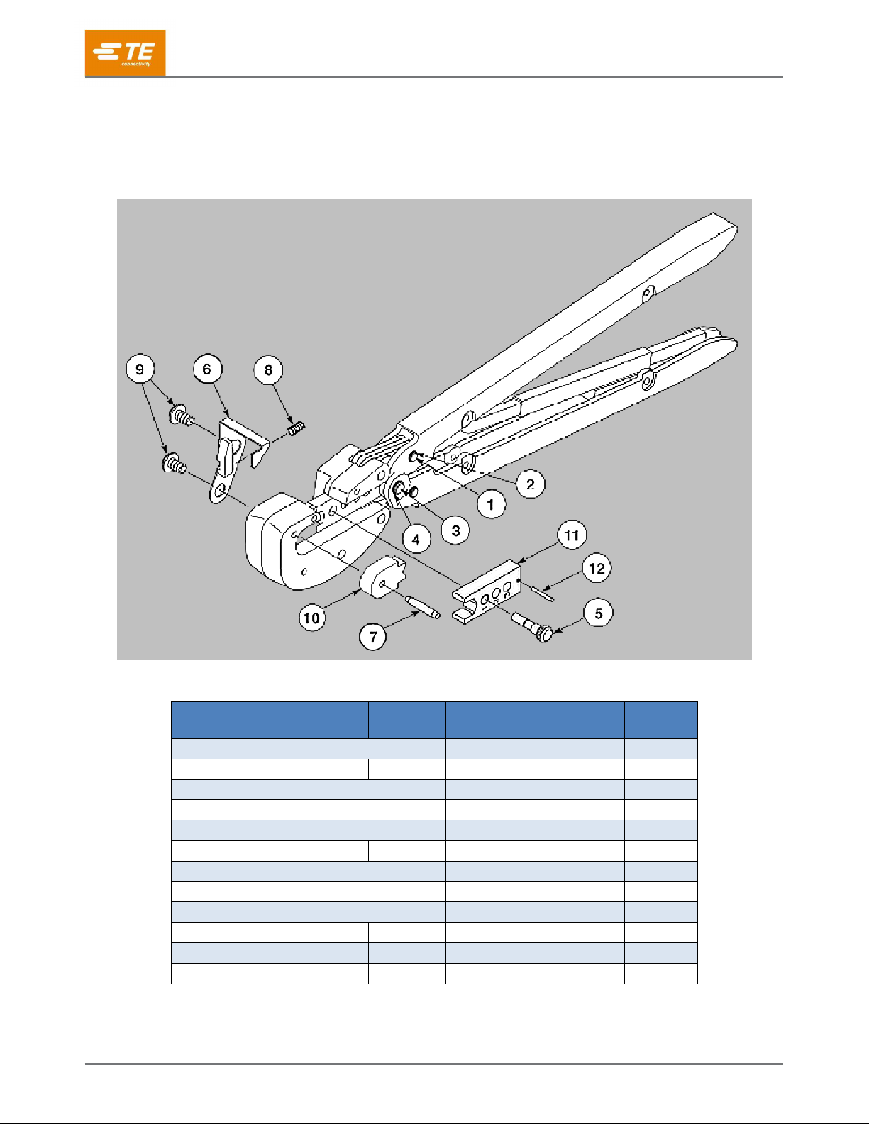
The parts listed in Table 6 are customer-replaceable. Stock and control a complete inventory to prevent lost
time when replacement of parts is necessary.
Figure 21: Replacement parts
Table 6: Replacement part numbers
Item
59239-4
59239-8
59287-2
525692
Description
Quantity
per tool
1
300388
Retaining pin
2
2
21045-3
525108
Retaining ring
4
3
300389
Retaining pin
1
4
21045-6
Retaining ring
2
5
303848-2
Adjustment pin assembly
1
6
306110-9
306110-4
306110-9
Stop locator
1
7
5-21028-7
Pin
1
8
7-59683-6
Spring
1
9
6-306131-4
Screw
2
10
306106-2
45891-8
306106-2
Stationary die (insulation)
1
11
306107-2
45888-7
306107-2
Moving die (insulation)
1
12
21028-4
21028-5
21028-4
Pin
1
Parts not listed in Table 6 should be replaced by TE Connectivity to ensure quality and reliability.

408-1261
Rev L
19 of 19
Order replacement parts through your TE representative. You can also order parts by any of the following
methods:
Go to TE.com and click the Shop TE link at the top of the page.
Call 800-522-6752.
Write to:
CUSTOMER SERVICE (038-035)
TE CONNECTIVITY CORPORATION
PO BOX 3608
HARRISBURG PA 17105-3608
For customer repair services, call 800-522-6752.
8 Revision summary
Since the last revision of this document, the following changes were made:
Reformatted and edited to conform to the current standard for instruction sheets
This manual suits for next models
3
Table of contents
Other TE Crimping Tools manuals


Popular Crimping Tools manuals by other brands


KIMBALL MIDWEST
KIMBALL MIDWEST K300 Series Operator's manual

molex
molex 63825-9400 Application Tooling Specification Sheet

Tyco Electronics
Tyco Electronics 1490749-1 instruction sheet

SharkBite
SharkBite 865894 Instruction guide

Textron
Textron Greenlee GATOR EK410LT Operation manual

molex
molex AT 2100 Operating Instruction Sheet And Specifications