TE Ocean 2.0 User manual

Instruction Sheet
1 of 30
© 2022 TE Connectivity Ltd. family of companies.
All Rights Reserved.
TE Connectivity, TE connectivity (logo), and TE (logo) are trademarks. Other logos, product, and/or company names may be trademarks of their respective owners.
PRODUCT INFORMATION
1-800-522-6752
This controlled document is subject to change.
For latest revision and Regional Customer Service,
visit our website at www.te.com.
408-35043
13 OCT 2022 Rev D
Figure 1: Ocean 2.0 end-feed applicators
1. INTRODUCTION
Ocean 2.0 end-feed applicators are available with a mechanical terminal feeder or a pneumatic terminal feeder
assembly. Each applicator accepts the end-feed strip-form of terminals identified on the applicator drawing to
apply to pre-stripped wires.
NOTE
Dimensions in this instruction sheet are in millimeters with [inches in brackets]. Figures are for reference only and are not
drawn to scale.
This instruction sheet, along with the parts list, exploded-view drawing (packaged with applicator), and
applicable terminating machine manual (Table 1), provide all the information required to operate and maintain
the applicator and machine.
Table 1: Terminating machine manuals
Machine
Manual
Basic AMP-O-LECTRIC™
409-5128
Model T
409-5207
409-5289
Model G
409-5842
AMP 3K™1725950-[ ]
AMP 5K™1725900-[ ]
409-10047
AMP 3K/40™2119683-[ ]
AMP 5K/40™2119684-[ ]
409-10099
NOTE
Refer to instruction sheet 408-35005 for translations of the safety warnings specified herein.
Ocean 2.0 End-Feed Applicators
408-35043
Rev D
2 of 30
2. DESCRIPTION
Figure 2 shows the main components of the mechanical feed applicator. Figure 3 shows the main components
of the air feed applicator.
Each applicator is individually designed for specific terminals. The wire crimp height and insulation crimp height
can be adjusted to accommodate different wire sizes and insulation ranges. The applicator is also designed to
accept modular-feed packages.
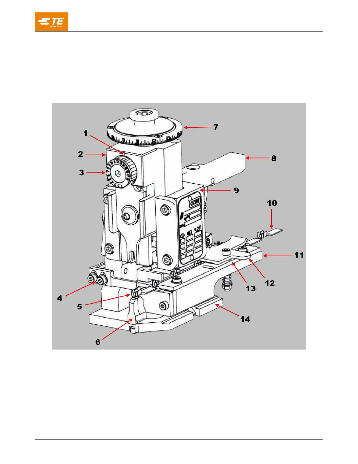
Figure 2: Mechanical feed applicator
1
Indicator notch / cutout
6
Anvil
11
Strip guide plate
2
Ram assembly
7
Wire crimp disc
12
Drag release lever
3
Insulation crimp dial
8
Terminal feeder assembly
13
Strip guide
4
Stripper
9
Applicator housing
14
Base plate
5
Lead terminal (for reference)
10
End-feed strip-form terminal strip

408-35043
Rev D
3 of 30
Figure 3: Air-feed applicator
1
Air feed cam
5
Extend speed control
2
Air supply connection
6
Feed arm
3
Locking nut
7
Feed pawl
4
Retract speed control
8
Mounting screws

408-35043
Rev D
4 of 30
The applicator is also designed to accept modular feed assemblies (Figure 4).
Figure 4: Feeder assemblies
1
Pneumatic terminal feeder assembly
2
Mechanical terminal feeder assembly
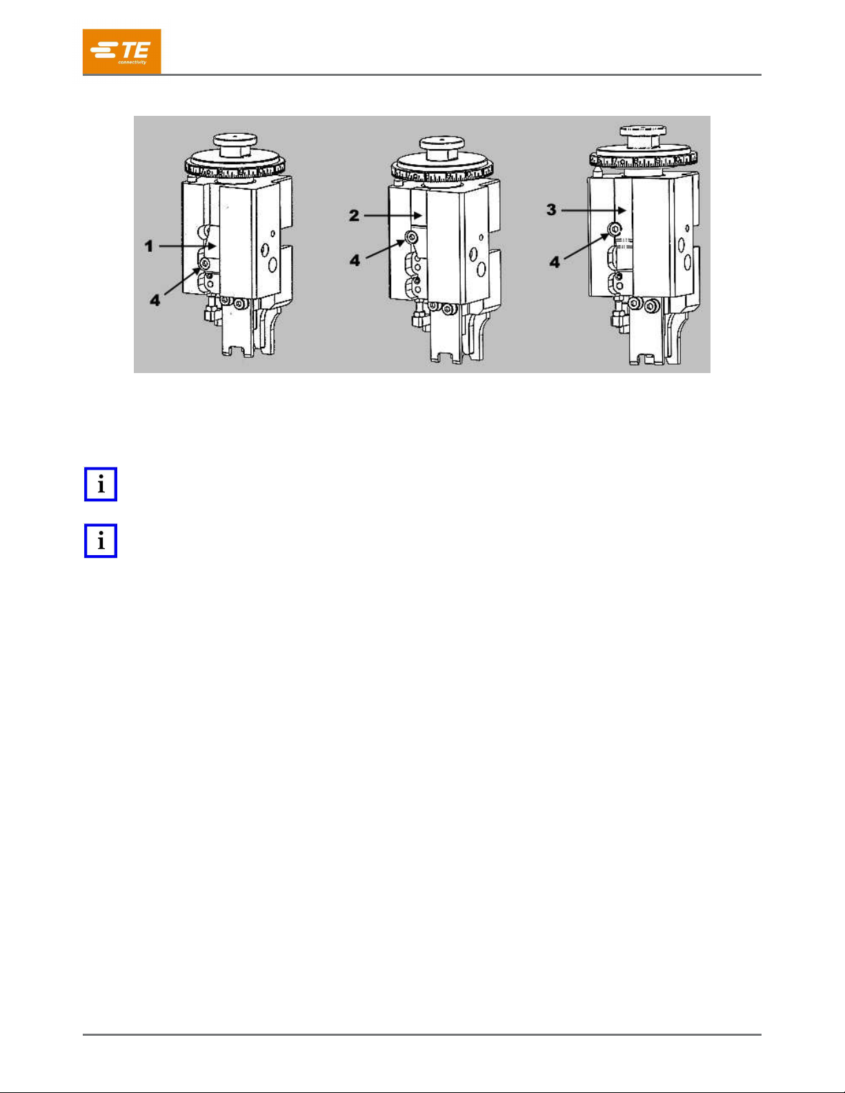
The Ocean applicator can be used in various machines, provided the machine has the proper stroke length and
all the necessary equipment. Two basic applicator design styles (Atlantic and Pacific) are available to meet
many of the terminator and leadmaker configurations worldwide (Figure 5). The applicator ram and base plate
interfaces are different, but most of the Ocean applicator features and adjustments are the same.
Figure 5: Basic applicator design styles
1
Atlantic
6
Wire crimp disc
11
Slug blade
2
Pacific
7
Insulation crimp dial
12
Wire crimper
3
Boss
8
Applicator ram
13
Insulation crimper
4
Machine ram for ram post adapter
9
Crimper bolt
14
Ram clamp
5
Ram post
10
Terminal hold-down

408-35043
Rev D
5 of 30
The terminal strip must be fed into the applicator, with the wire barrels facing up and first into the applicator,
between the strip guide plates. It passes under the stock drag, and the lead terminal is positioned over the anvil
(for pre-feed applicators) or one terminal length from the anvil (for post-feed applicators). The feed pawl feeds
one terminal during each cycle of the machine. The ram post (also referred to as the ram mounting post)
engages the post adapter of the machine ram, which actuates the applicator.
The wire crimp disc is located just below the ram post interface. The wire crimp disc is designed with a spring-
loaded adjustment mechanism for precise crimp height adjustment increments of 0.01 mm [.0004 in.] and a
total adjustment range of 1.50 mm [.059 in.]. By rotating the wire crimp disc, the ram interface raises and
lowers relative to the applicator housing. The indicator notch of the ram points to the numbers on the perimeter
of the wire crimp disc, indicating a relative crimp height. For proper crimp height, the number on the wire crimp
disc must correspond to the number on the applicator identification tag and drawing.
The wire and insulation crimpers are held in a pre-set position by the ram and the crimper bolt. The insulation
crimper is free to move up and down so that the insulation crimp height can be adjusted by pulling the spring-
loaded insulation crimp dial out slightly and rotating it to a different number.
The slug blade, which cuts the connection tab from the strip between the lead and second terminals, is also
attached to the bottom of the ram. The spring-loaded terminal hold-down, located on the ram, holds the
terminal in place during the crimping and slugging process.
The applicator mounting surface is the base plate. The anvil, strip guide plate, and applicator housing are
mounted on the base plate. The strip guides, stock drag, front and rear shear plates, and strip hold-down plate
are all mounted on the strip guide plate. The shear plates are spaced to allow the slug blade to pass between
them, removing the connecting tab between the terminals.
2.1. Terminal lubricant
Some terminal strips require the use of a terminal lubricant to reduce tooling wear and damage to the plating on
some terminals. Wick-type lubricators apply lubricant to the terminal strip as it feeds into the applicator. Ocean
applicator lubricator assembly PN 2119955-2 is available.
Disconnect electrical power when performing maintenance or repair on this equipment.
NOTE
The question of whether a lubricant is required depends on the final use of the crimped terminal. To determine whether your
applications warrant the use of a terminal lubricant, contact your TE representative. (See section 6Error! Reference source n
ot found. for contact information.)
If your application warrants the use of a terminal lubricant, use Stoner Terminal Lubricant E807 from Stoner,
Inc. Call 800-227-5538 or visit Stoner’s Critical Cleaning website.

408-35043
Rev D
6 of 30
2.2. Applicator with mechanical feed system
With this applicator (Figure 6), the terminals are fed by the action of the feed cam and a series of rods and
levers that move the feed pawl.
Figure 6: Applicator with mechanical feed system
1
Feed mounting screw (2 places)
7
Fine feed adjustment lock screw (far side)
2
Stroke length adjustment screw
8
Feed pawl pin
3
Stroke pivot
9
Feed pawl holder
4
Stroke length adjustment lock screw
10
Applicator counter set screw
5
Fine feed adjustment screw
11
Applicator counter
6
Stock drag adjustment nuts
12
Spare feed cam storage location

408-35043
Rev D
7 of 30
Two feed cams (Figure 7) can be used with the mechanical feed applicator.
The pre-feed cam advances the lead terminal over the anvil on the upward stroke of the ram assembly
so that a terminal is over the anvil when the machine is at rest. The pre-feed set up is typically used for
side-feed bench applications.
The post-feed cam advances the lead terminal over the anvil on the downward stroke of the ram
assembly. The post-feed set up is typically used for leadmaker and end-feed bench applications.
Figure 7: Mechanical feed cams
1
Pre-feed cam
2
Post-feed cam
These feed cams can be mounted in two different mounting holes, depending on machine stroke length and
feed type (Figure 8 and Figure 9). When not in use, the spare feed cam can be mounted to the applicator
housing in the spare feed cam storage location (Figure 6).
Figure 8: Mounting a feed cam on 40-mm [1⅝-in.] stroke machine
1
Mechanical pre-feed cam
2
Mechanical post-feed cam
3
Air-feed pre- or post-feed cam
4
Mounting screw
408-35043
Rev D
8 of 30
Figure 9: Mounting a feed cam on 30-mm [1⅛-in.] stroke machine
1
Mechanical pre-feed cam
2
Mechanical post-feed cam
3
Air-feed pre- or post-feed cam
4
Mounting screw
NOTE
Pacific applicators can only be used with 30-mm stroke machines. They have only the 30-mm feed cam mounting positions on
the applicator ram.
NOTE
The recommended setup for mechanical end-feed applications is post-feed. The applicator can be configured for pre-feed, but
this causes problems with some applications. Feed issues or terminal jamming can occur in the mechanical pre-feed
configuration.

408-35043
Rev D
9 of 30
2.3. Applicator with air feed system
With an air feed applicator (Figure 3), the terminals are fed by the action of an air feed module using a constant
air supply that moves the feed pawl. The speed control valves control the speed of the feed and retract strokes.
Two feed cams (Figure 10) can be used with the air feed applicator.
The supplied pre-feed feed cam advances the lead terminal over the anvil on the upward stroke of the
ram assembly, leaving a terminal over the anvil when the machine is at rest.
An optional post-feed cam (part number 2391975-1) is available. It advances the lead terminal over the
anvil on the downward stroke of the ram assembly, leaving the anvil clear when the machine is at rest.
Figure 10: Air feed cams
1
Pre-feed cam
2
Post-feed cam (optional)
These feed cams can be mounted in two different mounting holes, depending on machine stroke length and
feed type (Figure 8 and Figure 9).
The air supply connection (Figure 3) must be connected to an air supply line providing continuous
pressure of 5.00 to 6.00 bars [72 to 87 psi] at the applicator.
No oil lubrication of air is required for the Ocean air feed module after receiving and use within a
production environment.
The ram collar must be installed when changing crimp tooling to prevent the ram from becoming
captured. If this occurs, the air feed assembly must be removed to release the applicator ram.
CAUTION
The air feed housing has a vertical etched line that serves as a visual aid to ensure that the piston assembly is located within
the limits of the air cylinder position (see Figure 3). The feed pawl holder must be positioned to the right of the line. Incorrect
positioning of the feed pawl can cause the air feed module to fail prematurely.

408-35043
Rev D
10 of 30
2.4. Applicator with Pacific head
The Pacific applicator works only if the machine’s ram falls within the envelope shown in Figure 11.
(Dimensions are in millimeters, with inches in brackets.)
Figure 11: Ram dimensions for use with Pacific applicator
3. INSTALLING AND REMOVING THE APPLICATOR
Disconnect electrical power when performing maintenance or repair on this equipment.
Disconnect air supply when performing maintenance or repair on this equipment.
DANGER
To avoid personal injury, use the applicator only in an appropriate terminating machine. Do not connect the pressurized air
supply until after the applicator is properly installed.
CAUTION
With the applicator in the machine, do not attempt to cycle the machine under power unless the terminals have been properly
loaded, as described in section 4. Doing so can damage the tooling.
NOTE
Remove the ram transportation collar after installing the applicator on a machine. Do not reinstall the ram transportation collar
until you are ready to remove the applicator from the machine.

408-35043
Rev D
11 of 30
3.1. AMP-O-LECTRIC and Model K machines (with mini-applicator conversion)
Installation
This machine must be equipped with machine conversion kit PN 690675-2 to adapt it for use with
miniature applicators. The kit includes applicator instruction sheet 408-8022, which explains how to install
and remove an applicator with a mechanical feed.
Removal
1. Turn off the machine.
2. Disconnect the power cord.
3. Unload the applicator as described in section 4.
4. Remove the hold-down bracket and movable stop.
5. Slide the applicator away from the stop on the base mount until the ram post is clear of the
machine ram.
3.2. Model T terminating unit (Atlantic only)
Installation
1. Turn off the machine.
2. Disconnect the power cord.
3. Push in the release bar on the quick-change base plate. The locking latch pivots downward.
4. Place the applicator on the quick-change base plate.
5. Slide it back until two notches engage the stops at the back of the plate, while guiding the ram
post into the ram post adapter.
6. Flip the locking latch up to secure the applicator in place.
Removal
1. Turn off the machine.
2. Disconnect the power cord.
3. Cut the terminal strip one or two terminals from the end of the applicator.
4. Push in the release bar on the quick-change base plate. The locking latch pivots downward.
5. Slide the applicator forward until it is clear of the ram post adapter.
3.3. Other terminating machines
Refer to the appropriate machine manual (Table 1) for installation and removal procedures for the following
machines:
Basic AMP-O-LECTRIC
Model G
AMP 3K
AMP 5K
AMP 3K/40
AMP 5K/40
For any other terminating machines, refer to the customer documentation supplied with the machine.
NOTE
When switching between the bench terminator and an automatic leadmaker, you might have to adjust the wire stripper up or
down.

408-35043
Rev D
12 of 30
4. LOADING AND UNLOADING THE TERMINAL STRIP
4.1. Loading the terminal strip
1. Make sure that the installed applicator is the right one for the terminal to be applied. Compare the
terminal part number on the reel with the numbers listed on the applicator parts list.
2. Turn off the machine.
3. Disconnect the power cord.
4. Make sure that the ram assembly is all the way up. If necessary, hand-cycle the machine to raise the
ram. Refer to the machine customer manual.
5. Remove the applicator guard assembly.
6. Raise the stock drag by turning the drag release lever upward.
7. Remove a length of the terminal strip left in the applicator by grasping the terminals at the strip guide
entry, raising the feed pawl, and pulling the strip straight out of the applicator.
8. With the reel of terminals installed on the reel support, feed the terminal strip into the applicator
between the strip guides with the terminal wire barrel entering first and the open side of the wire barrel
facing up.
9. Raise the feed pawl and continue to feed the terminal strip until the lead terminal is over the anvil and
the feed pawl engages the terminal in the proper position.
10. If terminals are post-feed, lift the feed pawl and pull the strip back one terminal length. The lead
terminal is moved over the anvil on the downward stroke of the ram assembly. Make sure that the tip of
the feed pawl is in the feed hole of the carrier strip.
NOTE
Some carrier strips have additional holes that are not used for feed purposes.
11. Hand-cycle the machine several times to make sure the applicator is properly adjusted as described in
section 5.
12. Reinstall the applicator guard assembly.
4.2. Unloading the terminal strip
Remove the strip section only as part of the loading procedure. It is not necessary to remove it for cleaning,
lubrication, or repair.
1. Cut the terminal strip one or two terminals from the end of the applicator.
2. If terminals are post-feed, turn the drag release lever upward to raise the stock drag, lift the feed pawl,
and move the lead terminal over the anvil.
408-35043
Rev D
13 of 30
5. ADJUSTMENTS
5.1. Adjusting the wire crimp height
1. Select an increment number from the data plate for the wire size to be used.
Values range from 0 (the largest crimp height) to 150 (the smallest).
Each increment represents a change in crimp height of 0.01 mm [.0004 in.].
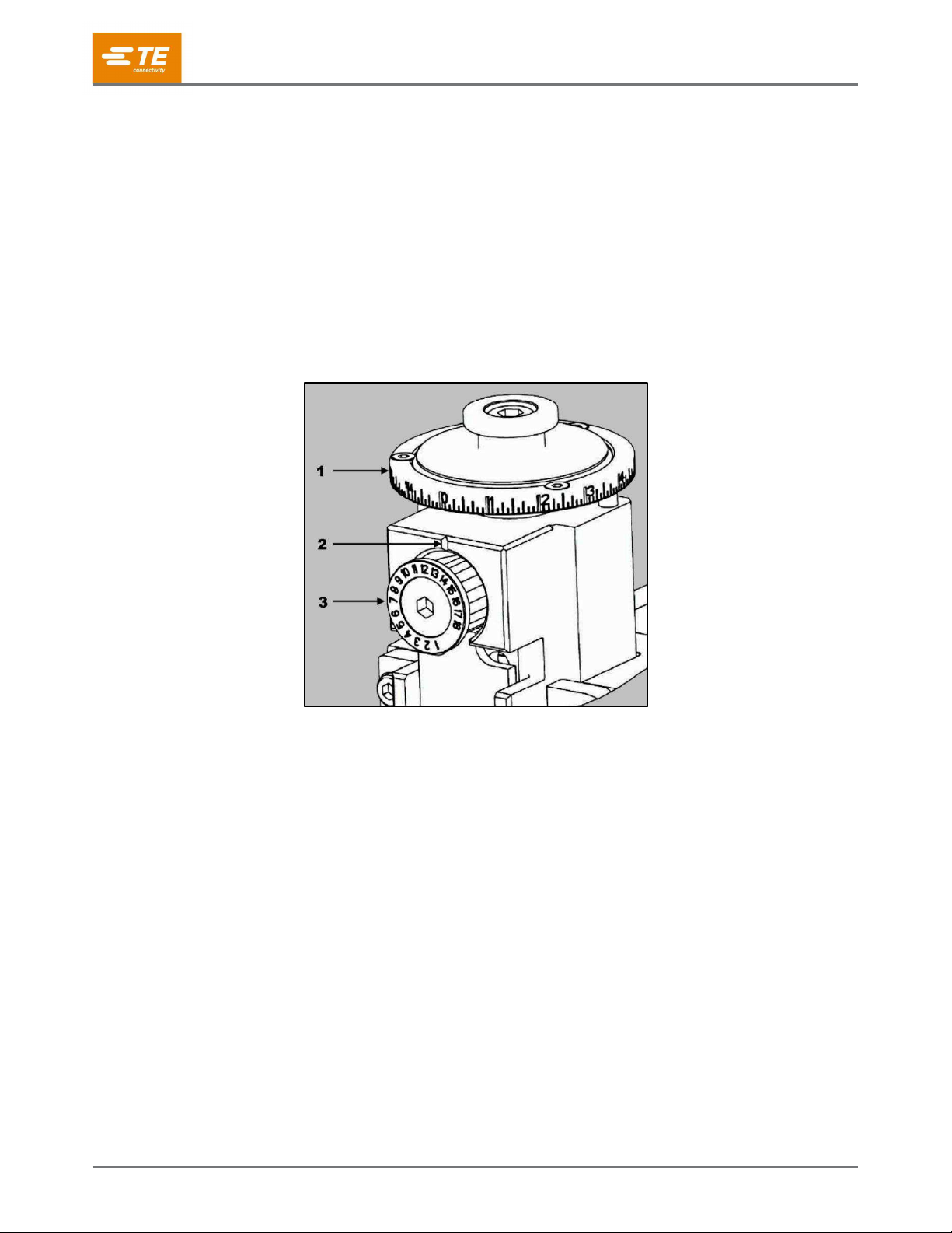
2. Adjust the crimp height by turning the wire crimp height adjustment disc until the required increment
number lines up with the indicator notch on the front of the ram (Figure 12).
Turn the disc clockwise to decrease the crimp height.
Turn the disc counter-clockwise to increase the crimp height.
Figure 12: Wire crimp height adjustment disc
1
Wire crimp disc
2
Indicator notch
3
Insulation crimp dial
3. Adjust the insulation crimp as described in section 5.3.
4. Make several test cycles and inspect the terminations closely. Look for rough or sharp edges around
the crimped barrels (flash), deformed crimps, bent terminals, or other defects caused by worn or
broken tooling. If necessary, replace the tooling as described in section 6.
If the terminations appear normal, measure the crimp height of each termination as described in
instruction sheet 408-7424 (packaged with the applicator). The crimp height must agree with the
measurement specified on the applicator drawing for the wire size being used. Record crimp height
dimensions for reference.
If the crimp height is incorrect, remove the applicator and install one that is known to produce
terminations of correct crimp height.
5. Make several test cycles and repeat the inspection.
If the crimp height is incorrect for this applicator, the problem is the machine shut height. Refer to
the appropriate machine manual (Table 1) for corrective measures.
If the crimp height is correct, the problem is in the original applicator. Refer to section 6.6,
Repairing the adjustable crimp height, for corrective measures.
6. During extensive operation, periodically inspect the terminals as described in step 4 to ensure that the
applicator is producing correct terminations.
408-35043
Rev D
14 of 30
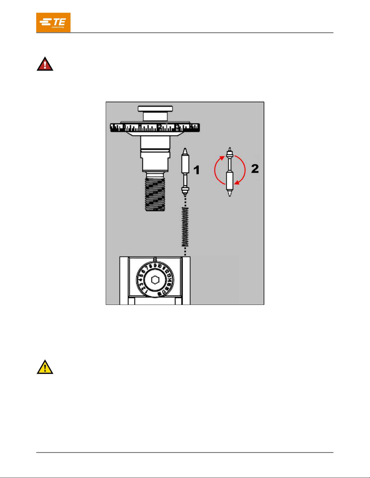
5.2. Locking the wire crimp position
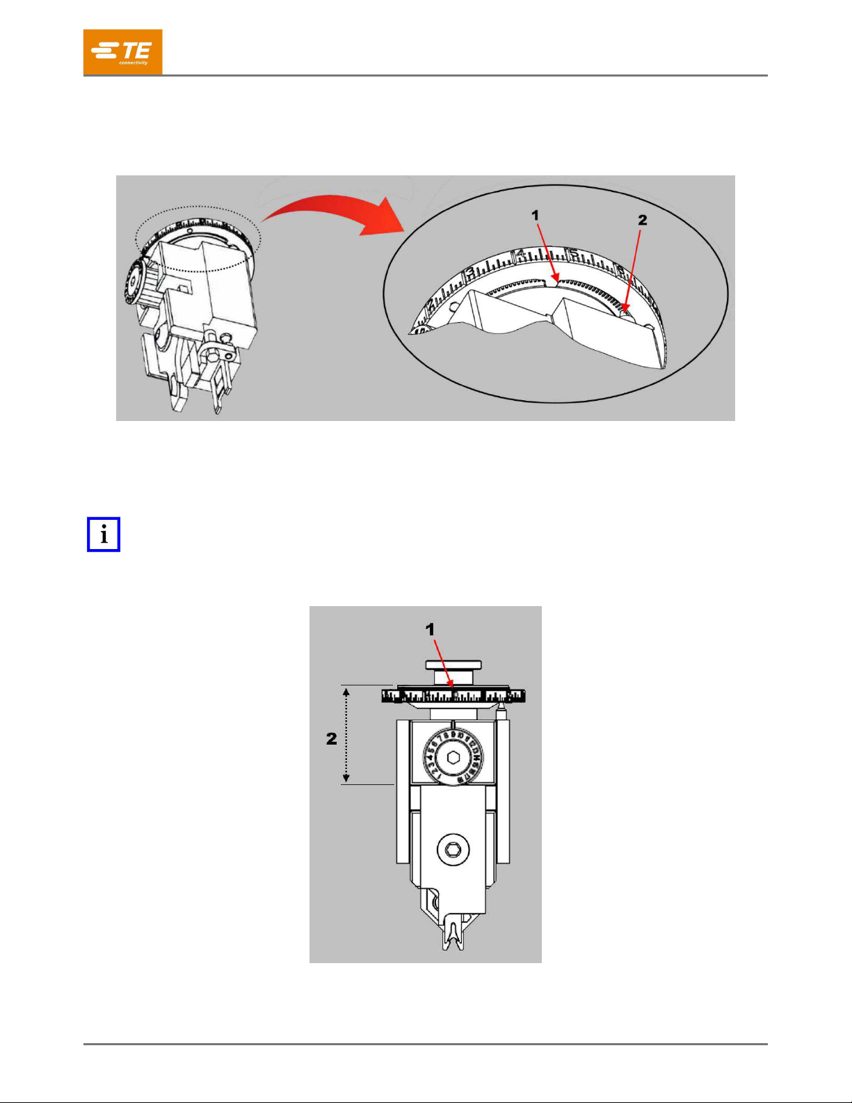
The wire crimp height adjustment can be locked in position by inverting the detent pin (see Figure 13).
Figure 13: Location of detent pin
1
Ring stop
2
Detent pin
1. Verify the fine adjustment head setup distance (the distance from the crimper seating feature on the
ram to the top of the crimp height adjustment head). See Figure 14.
NOTE
Some applicators have a special insulation adjustment dial with different range and increments. Refer to the marking on the
front of the insulation crimp dial for correct increments.
Figure 14: Setup distance
1
Adjustment set to zero
2
Fine adjustment head setup distance
408-35043
Rev D
15 of 30
2. While holding down the spring-loaded detent pin, turn the adjustment head clockwise until the detent
pin can be removed.
DANGER
The spring-loaded pin can injure you if released unexpectedly.
3. Invert the pin so that the locking end contacts the detent plate (Figure 15).
Figure 15: Inverting the detent pin
1
Detent orientation
2
Lock orientation
4. Reinstall the pin and spring.
5. While holding the pin down, turn the adjustment head until the proper set-up dimension is reached.
6. Verify the crimp height as shown in section 5.1.
CAUTION
When changing crimp height while in the locked orientation, the spring-loaded detent pin must be depressed to rotate the
number ring. Failure to do so damages the ring.
408-35043
Rev D
16 of 30
5.3. Adjusting the insulation crimp
The insulation crimp is adjustable in increments of 0.19 mm [.0075 in.]. Pull the insulation crimp dial out (refer
to Figure 5) and turn it to line up with a number (1 through 18) so that it is shown at the indicator notch on the
ram.
Number 1 makes the loosest crimp.
Number 18 makes the tightest crimp.
The total range of adjustment is approximately 3.30 mm [.130 in.]. Start with number 1 and make test crimps
while increasing the setting one number at a time until the proper insulation crimp height is achieved.
NOTE
Some applicators have a special insulation adjustment dial with different range and increments. Refer to the marking on the
front of the insulation crimp dial for correct increments.
5.4. Adjusting the terminal strip feed
Mechanical feed applicator
NOTE
When adjusting a mechanical feed applicator, always start by properly adjusting the stroke length. Then adjust the fine feed
adjustment to position the terminal over the anvil.
1. With the terminal strip properly loaded, check the position of the lead terminal relative to the slug blade.
Position the feed pawl in the required location on the terminal (typically the end of the wire barrel).
Refer to Figure 6. The slug blade must remove the connecting tab between lead and second terminals
without deforming either terminal.
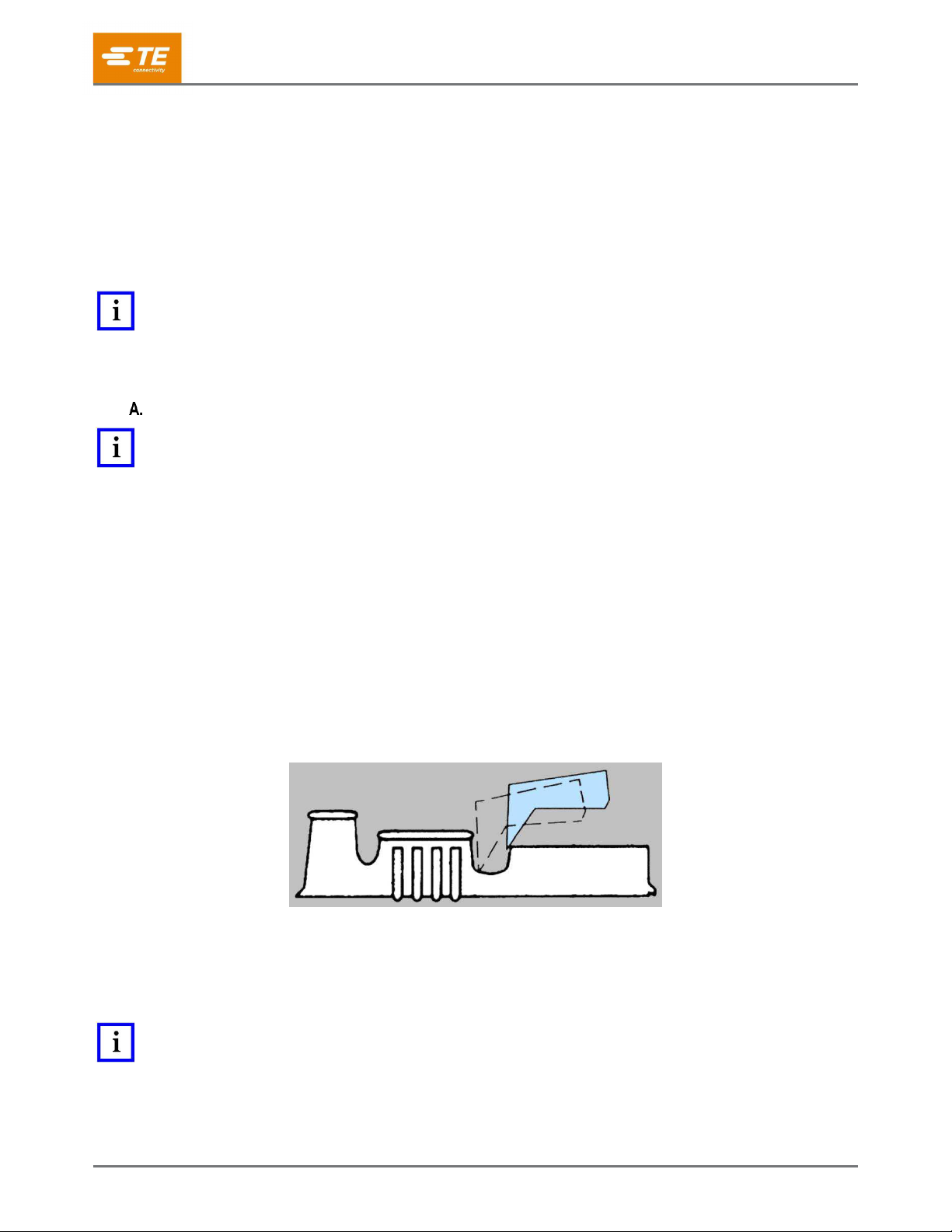
2. Watch the feed pawl as the machine is hand-cycled (or slowly cycled) several times. It should have
enough over-travel on the backstroke to pick up the next terminal, but not so much over-travel that the
feed pawl moves up onto the body of the terminal (see Figure 16).
If the pick-up point is the mating end of the terminal, the backstroke over-travel should be about
equal to the distance between the wire barrel and the mating end of the terminal (Figure 2).
For other types of terminals (for example, ring tongue), over-travel should be about the same,
depending on the terminal features and configurations (for example, stud hole).
Figure 16: Feed pawl backstroke over-travel
3. Check the backstroke position.
If the backstroke position is correct, the tab is correctly slugged out, and the terminals are not
damaged, the feed adjustments are complete.
If not, continue to the next step.
NOTE
Two adjustments work in combination to properly position the lead terminal over the anvil and give the proper backstroke
position to pick up the next terminal feed hole. Use one or both adjustment types to properly adjust the applicator.

408-35043
Rev D
17 of 30
4. If the slug blade does not shear the terminal in the correct position, make note of the position and
continue to cycle the applicator to check the backstroke position. If the lead terminal is not slugged out
correctly and the backstroke position is incorrect, both the stroke length and the fine feed position must
be adjusted. Stroke length (backstroke position) must be adjusted before final centering of other
terminals under the slug blade.
a. Loosen the stroke length adjustment lock screw (see Figure 6).
b. Turn the stroke length adjustment screw to adjust the stroke length.
Turn the screw counter-clockwise to reduce the stroke length.
Turn the screw clockwise to increase the stroke length.
c. Tighten the stroke length adjustment lock screw.
5. Repeat steps 1 through 4 as required until the proper stroke length is achieved.
6. If the feed pawl stroke length is satisfactory and the backstroke position is correct, but the lead terminal
is not slugged out correctly (or positioned under the slug blade correctly) and the stroke is correct, but
the position is incorrect, an adjustment to the fine feed screw is required.
a. Loosen the fine feed adjust lock screw on the side of the feed pawl holder to allow the fine feed
adjustment screw to turn. Refer to Figure 6.
CAUTION
Do not remove the fine feed adjust lock screw. A nylon plug is captured behind the lock screw. Loss of this plug causes
damage to the fine feed adjustment screw threads when the lock screw is tightened.
b. Turn the adjustment screw to position the feed pawl and place the terminal under the slug blade.
Turn the screw counter-clockwise to move the feed pawl away from the anvil.
Turn the screw clockwise to move the feed pawl toward the anvil.
c. Tighten the lock screw to secure the fine feed adjustment screw.
7. Re-check the adjustment for the proper position and stroke as described in step 1. Repeat the
adjustment procedure as necessary.
Air feed applicator
DANGER
To avoid personal injury, use this applicator only in an appropriate terminating machine.
DANGER
To avoid personal injury, do not connect the pressurized air supply until after the applicator is properly installed in the
terminating machine. When the machine is manually cycled, the mechanism moves forward and backward once during each
machine stroke, unless the air is disconnected.
DANGER
Moving parts can crush and cut. Never insert hands into installed equipment.
DANGER
Do not wear jewelry, loose clothing, or long hair that can catch in moving parts of the equipment.
DANGER
Do not operate the equipment without guards in place.
CAUTION
Do not tamper with the set screws located in the air feed valve assembly.
NOTE
The life of the piston seal can be extended by applying either MAGNALUBE™-G or Parker Super O-lube to the air cylinder
piston shaft.

408-35043
Rev D
18 of 30
Adjusting the feed
The feed stroke (terminal pitch), terminal position, and feed speed adjustments are set at the factory. If
adjustment is necessary, follow the instructions below:
If the pick-up point is the end of the wire barrel, the backstroke over-travel (Figure 16) should
be approximately equal to the distance between the wire barrel and the mating end of the
terminal.
For other types of terminals (for example, ring tongue), over-travel should be about the same,
depending on the terminal features and configurations (for example, stud hole).
Adjusting the feed stroke
1. Remove air pressure from the air feed module.
2. Release terminal drag.
3. Install the terminal strip in the applicator until the feed pawl drops into the backstroke position
(Figure 17).
Figure 17: Feed pawl in backstroke position
4. Engage terminal drag.
5. Manually extend the feed arm.
6. Manually retract the slide until the feed pawl is at the backstroke position for the next terminal.
408-35043
Rev D
19 of 30
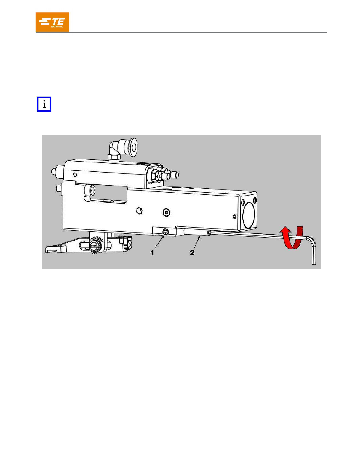
7. If the feed pawl reaches the backstroke position before the slide hits the rear stop adjustment
screw, adjust the rear stop adjustment screw.
a. Loosen the rear stop locking screw (Figure 19).
b. Turn the rear stop adjustment screw clockwise until it meets the slide.
c. Verify that the feed pawl is in the backstroke position.
d. Tighten the locking screw.
NOTE
Use a 2.5mm ball end hex key wrench to adjust the feed stroke and feed positions. One-quarter turn of the rear stop
adjustment screw adjusts the backstroke 0.20mm (0.008 inch).
Figure 18: Rear stop locking screw
1
Rear stop adjustment screw
2
Rear stop locking screw
8. If the slide hits the rear stop adjustment screw before the feed pawl reaches the backstroke
position, adjust the rear stop adjustment screw.
a. Loosen the rear stop locking screw.
b. Turn the rear stop adjustment screw counter-clockwise.
c. Push the slide against the rear stop adjustment screw.
d. Verify that the feed pawl is in the backstroke position. If not, repeat substeps b and c.
e. Tighten the locking screw.
9. Extend and retract the slide by hand. Verify that the feed finger is in the backstroke position. If
not, repeat steps 7 and 8 to adjust the feed stop position of the feed finger.
10. Apply pressurized air to the air feed module.
11. Cycle the terminator in jog mode or by hand until the feed pawl retracts.
12. Verify that the pawl is in the correct location. If not, repeat steps 6 through 10.

408-35043
Rev D
20 of 30
Adjusting the feed position
NOTE
It is not necessary to remove air pressure from the air feed module before making a feed adjustment.
1. Extend the feed fully.
2. Retract the feed fully. The terminal should be positioned over the anvil.
3. If the terminal is not over the anvil, turn the feed adjustment screw (Figure 19) to reposition the
terminal (Figure 16).
If the terminal stops before the anvil (underfed), turn the screw clockwise.
If the terminal is past the anvil (overfed), turn the screw counter-clockwise.
NOTE
One click of the feed adjustment screw equals 0.025mm (0.001 inch) of adjustment. Make small adjustments before checking
the feed.
4. Retract the feed slide and terminals by pulling back on the terminal strip.
5. Extend the feed slide to feed a terminal.
6. If the terminal is not centered properly, repeat step 3.
Figure 19: Feed adjustment screw
1
Feed arm
2
Feed adjustment screw
Table of contents
Other TE Crimping Tools manuals


