manuals.online logo
Brands
  1. Home
  2. •
  3. Brands
  4. •
  5. Tyco Electronics
  6. •
  7. Crimping Tools
  8. •
  9. Tyco Electronics 1490749-1 User manual

Tyco Electronics 1490749-1 User manual

Instruction Sheet
Hydraulic
Hand Crimping 408-8717
L C B
1
of 3
E
2008 Tyco Electronics Corporation, Harrisburg, PA
All International Rights Reserved
TE logo and Tyco Electronics are trademarks.
*Trademark. ther products, logos, and company names used are the property of their respective owners.
T LING ASSISTANCE CENTER 1-800-722-1111
PR DUCT INF RMATI N 1-800-522-6752 This controlled document is subject to change.
For latest revision and Regional Customer Service,
visit our website at
www.tycoelectronics.com
27 CT 08 Rev A
Tool 1490749-1
PROPER USE GUIDELINES
CumulativeTrauma Disorderscanresultfromtheprolongeduseofmanuallypoweredhandtools.Handtoolsareintendedforoccasionaluseandlowvolume
applications. A wide selection of powered application equipment for extended-use, production operations is available.
–
–
–
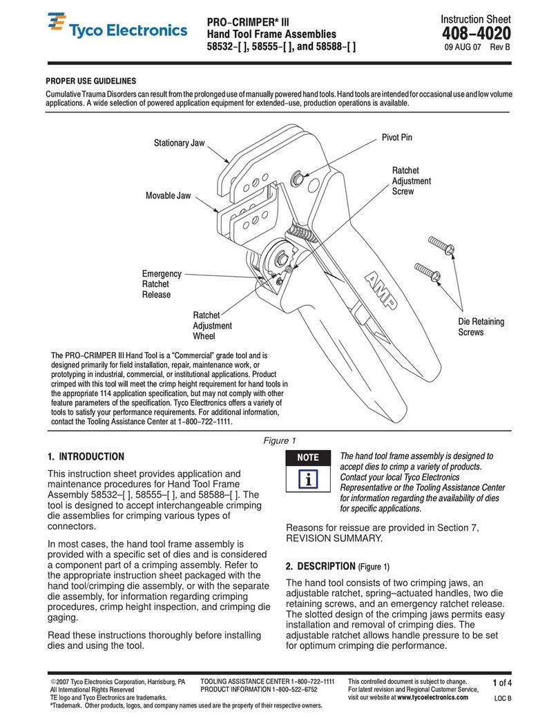
Figure 1
Movable Lever
Stationary Lever
Moving Die Release Button
Ram
C"-Head
Plunger
Striker (Shown in Actuated
Positon to Depress Plunger)
Stationary Die Release Button
1. INTRODUCTION
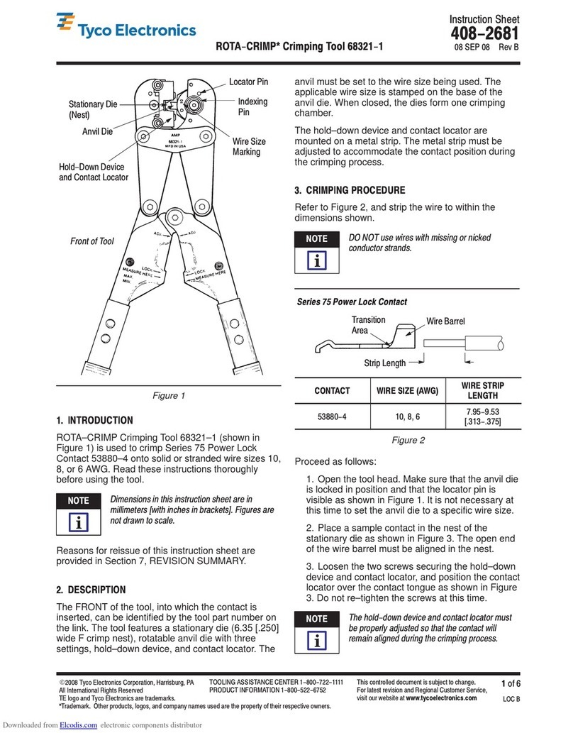
Hydraulic Hand Crimping Tool 1490749–1 (Figure 1)
is designed for crimping the terminals and splices in
Figure 2. Read these instructions thoroughly before
using the hand tool.
TERMINALS WIRE SI E
(AWG) INSTRUCTION
SHEET
AMP WER*
Terminals and Splices 6 Through 4/0 408-8703
S LISTRAND*
Terminals and Splices 8 Through 4/0 408-8691
TERMINYL*
Terminals and Splices 8 Through 1/0 408-8704
AMPLI-B ND*
Terminals and Splices 8 Through 2 408-8705
Figure 2
Dimen ion in thi in truction heet are in metric
unit [with U.S. cu tomary unit in bracket ].
Figure and illu tration are for identification only
and are not drawn to cale.
2. DESCRIPTION
(Figure 1)
The hand tool has a stationary lever and a movable
lever. These levers are compressed to pump
hydraulic fluid behind the ram, moving it forward and
thereby closing the dies. After the crimping is
complete, the movable lever is turned to depress the
plunger. The moving die retracts to its original
position, completing the crimping cycle.
3. DIE INSERTION AND REMOVAL
To avoid damage to the tooling, never operate
the tool with the die removed. Failure to in ert
the die before operation can re ult in damage to
the C"-Head or the tool ram.
Before inserting dies, refer to instruction sheet
packaged with dies for detailed instructions: insert or
remove dies, as necessary, by following procedures
given in the instruction sheet for the dies.
4. CRIMPING PROCEDURE
1. Strip wires to dimensions specified on the
instructions packaged with dies (see Figure 2).
2. Insert the terminal or splice in stationary die
according to instruction sheet packaged with dies.
To avoid per onal injury, be ure to exerci e
caution while holding terminal , plice , or wire in
the crimping area.
3. Pump movable lever until moving die grips
terminal or splice.
Do not deform wire barrel of terminal or plice.
NOTE
i
CAUTION
!
DANGER
CAUTION
!
408-8717
Hydraulic Hand Crimpin Tool 1490749-1
Rev
A2
of 3 Tyco Electronics Corporation
4. Insert stripped wire into wire barrel of terminal or
splice.
5. Continue pumping movable lever. A slight click
may be heard, indicating the pump has shifted into
the high–pressure stage. Continue pumping
movable lever and completely crimp the connector.
This tool has a built–in by–pass cartridge that will
automatically activate when full pressure is
reached. There will be a noticeable decrease in
handle pressure when the by–pass is reached.
A high itched squeaking sound is normal when
the tool is o erating in the high ressure stage.
6. Turn movable lever (to actuate striker), and
compress levers to depress plunger. Movable die
will now retract. See Figure 1.
7. Remove the crimped terminal or splice.
If terminal or s lice sticks in die after crim ing,
a ly a rocking action to remove it from die.
8. Inspect the crimped terminal or splice according
to inspection procedure on instruction sheet
packaged with the dies.
5. MAINTENANCE AND INSPECTION
It is recommended that a maintenance and inspection
program be performed periodically to ensure
dependable and uniform terminations.
The hand tool is inspected before being shipped;
however, It is recommended that the tool be
inspected immediately upon arrival at your facility to
ensure that the tool has not been damaged during
shipment.
5.1. Daily Maintenance
1. Immerse the hand tool (levers partially closed)
in a reliable commercial degreasing compound to
remove accumulated dirt, grease, and foreign
matter. When degreasing compound is not
available, wipe the tool clean with a soft, lint–free
cloth. Do NOT use hard or abrasive objects that
could damage the tool.
2. Protect all pins, pivot points, and bearing
surfaces with a THIN coat of any good grade
SAE 20 motor oil. Do NOT oil excessively.
3. When the tool is not in use, keep the levers
closed to prevent objects from becoming lodged in
the dies. Store the tool in a clean dry area.
5.2. Periodic Inspection
Though recommendations call for at least one
inspection a month, actual frequency depends on:
S
The care, amount of use, and handling of the
hand tool.
S
The presence of abnormal amounts of dust and
dirt.
S
The degree of operator skill.
S
Your own established standards.
A.
Lubrication
Keep all pins, pivot points, and bearing surfaces
lubricated with SAE 20 motor oil as follows:
Tool used in daily production—lubricate daily
Tool used daily (occasionally)—lubricate weekly
Tool used weekly—lubricate monthly
Wipe excess oil from tool, particularly from crimping
area. Oil transferred from the crimping area onto
certain terminations may affect the electrical
characteristics of an application.
A slight wee ing of oil from the ram and um
seals is normal and required to kee the moving
arts lubricated. Excessive leakage indicates a
need for seal re lacement. Refer to Section 6,
RETURN/REPLACEMENT.
B. Visual Inspection
1. Make certain all retaining pins are in place and
secured with retaining rings. If replacements are
necessary, return the tool for repair. See Section 6,
RETURN/REPLACEMENT.
2. Inspect for worn, cracked, or broken areas. If
damage is evident, return the tool for evaluation
and repair as described in Section 6,
RETURN/REPLACEMENT.
C. Crimpin Pressure Inspection
Check the crimping pressure to ensure that dies are
fully bottomed before pressure is reduced by the
internal bypass valve. The inspection should be
performed using each set of dies that will be used in
the tool.
1. Install dies according to Section 3, DIE
INSERTION AND REMOVAL, and the instruction
sheet packaged with the dies.
2. Select wire and terminal or splice for dies being
used.
3. Place terminal or splice in dies according to
instruction sheet packaged with dies.
4. Perform crimping procedure as described in
Section 4, CRIMPING PROCEDURE, Steps 3
through 5. Do not release hydraulic pressure at this
time.
NOTE
i
NOTE
i
NOTE
i

408-8717
Hydraulic Hand Crimpin Tool 1490749-1
3
of 3Rev
A
Tyco Electron cs Corporat on
5. Check the clearance between bottoming
surfaces of crimping dies. If clearance is 0.025 mm
[.001 in.] or less, the crimp pressure is satisfactory.
If clearance exceeds 0.025 mm [.001 in.], the
crimp pressure is
not
considered satisfactory. See
Section 6, RETURN/REPLACEMENT.
If the tool conforms to these inspection procedures,
lubricate it with a THIN coat of any good grade
SAE 20 motor oil and return it to service.
6. RETURN/REPLACEMENT
Order replacement parts through your Tyco
Electronics Representative, or call 1–800–526–5142,
or send a facsimile of your purchase order to
1–717–986–7605, or write to:
CUSTOMER SERVICE (38–35)
TYCO ELECTRONICS CORPORATION
P.O. BOX 3608
HARRISBURG, PA 17105–3608
Crimping heads may also be returned for evaluation
and repair. For tool repair service, contact a Tyco
Electronics Representative at 1–800–526–5136.
7. REVISION SUMMARY
S
Updated document to corporate requirements
S
New format
–
–
–
Figure 3
150 mm
[5.9 In.]
(Closed)
640 mm
[25.2 In.]
We ght: 7.8 kg (17.2 lb)

Other Tyco Electronics Crimping Tools manuals

Tyco Electronics PRO-CRIMPER III 58603-1 User manual

Tyco Electronics

Tyco Electronics PRO-CRIMPER III 58603-1 User manual

Tyco Electronics PRO-CRIMPER III User manual

Tyco Electronics

Tyco Electronics PRO-CRIMPER III User manual

Tyco Electronics PRO-CRIMPER III User manual

Tyco Electronics

Tyco Electronics PRO-CRIMPER III User manual

Tyco Electronics PRO-CRIMPER III User manual

Tyco Electronics

Tyco Electronics PRO-CRIMPER III User manual

Tyco Electronics AMP CERTI-CRIMP II User manual

Tyco Electronics

Tyco Electronics AMP CERTI-CRIMP II User manual

Tyco Electronics 0-0654174-1 User manual

Tyco Electronics

Tyco Electronics 0-0654174-1 User manual

Tyco Electronics PRO-CRIMPER III User manual

Tyco Electronics

Tyco Electronics PRO-CRIMPER III User manual

Tyco Electronics CERTI-CRIMP 90418-1 User manual

Tyco Electronics

Tyco Electronics CERTI-CRIMP 90418-1 User manual

Tyco Electronics PRO-CRIMPER III User manual

Tyco Electronics

Tyco Electronics PRO-CRIMPER III User manual

Tyco Electronics 1901820-1 User manual

Tyco Electronics

Tyco Electronics 1901820-1 User manual

Tyco Electronics AMP 91907 User manual

Tyco Electronics

Tyco Electronics AMP 91907 User manual

Tyco Electronics 58425 Series User manual

Tyco Electronics

Tyco Electronics 58425 Series User manual

Tyco Electronics 69067 User manual

Tyco Electronics

Tyco Electronics 69067 User manual

Tyco Electronics 58569-1 User manual

Tyco Electronics

Tyco Electronics 58569-1 User manual

Tyco Electronics PRO-CRIMPER III User manual

Tyco Electronics

Tyco Electronics PRO-CRIMPER III User manual

Tyco Electronics PIDG STRATO-THERM 1-576778-0 User manual

Tyco Electronics

Tyco Electronics PIDG STRATO-THERM 1-576778-0 User manual

Tyco Electronics PRO-CRIMPER III User manual

Tyco Electronics

Tyco Electronics PRO-CRIMPER III User manual

Tyco Electronics PRO-CRIMPER III User manual

Tyco Electronics

Tyco Electronics PRO-CRIMPER III User manual

Tyco Electronics PRO-CRIMPER III User manual

Tyco Electronics

Tyco Electronics PRO-CRIMPER III User manual

Tyco Electronics SDE PEW-12 User manual

Tyco Electronics

Tyco Electronics SDE PEW-12 User manual

Tyco Electronics STRATO-THERM 1-46673-0 User manual

Tyco Electronics

Tyco Electronics STRATO-THERM 1-46673-0 User manual

Tyco Electronics SOLARLOK 1579004-9 User manual

Tyco Electronics

Tyco Electronics SOLARLOK 1579004-9 User manual

Tyco Electronics 9-1478246-0 User manual

Tyco Electronics

Tyco Electronics 9-1478246-0 User manual

Tyco Electronics PRO-CRIMPER III User manual

Tyco Electronics

Tyco Electronics PRO-CRIMPER III User manual

Popular Crimping Tools manuals by other brands

Emerson Klauke ES 20RMCCFB manual

Emerson

Emerson Klauke ES 20RMCCFB manual

Greenlee GATOR EK622PLX Operation manual

Greenlee

Greenlee GATOR EK622PLX Operation manual

haupa AC25-12 instruction manual

haupa

haupa AC25-12 instruction manual

Limora 532167 quick start guide

Limora

Limora 532167 quick start guide

Klauke TEXTRON K502 instruction manual

Klauke TEXTRON

Klauke TEXTRON K502 instruction manual

Emerson Klauke EK 60/22CFB manual

Emerson

Emerson Klauke EK 60/22CFB manual

molex 63825-9400 Application Tooling Specification Sheet

molex

molex 63825-9400 Application Tooling Specification Sheet

Panduit CTFP-100 operating instructions

Panduit

Panduit CTFP-100 operating instructions

molex 64001-7300 Operating Instruction Sheet And Specifications

molex

molex 64001-7300 Operating Instruction Sheet And Specifications

JAE 3502-MX80-2 Operation manual

JAE

JAE 3502-MX80-2 Operation manual

Milwaukee M18 FORCE LOGIC 2678-20 Operator's manual

Milwaukee

Milwaukee M18 FORCE LOGIC 2678-20 Operator's manual

Cembre HT131-C Operation and maintenance manual

Cembre

Cembre HT131-C Operation and maintenance manual

Textron Klauke ESM 50CL manual

Textron

Textron Klauke ESM 50CL manual

Emerson Klauke EK 60VPCFB manual

Emerson

Emerson Klauke EK 60VPCFB manual

Hilpress 11302 operating instructions

Hilpress

Hilpress 11302 operating instructions

Danfoss FT1330 Operator's manual

Danfoss

Danfoss FT1330 Operator's manual

molex 63801-8500 instruction manual

molex

molex 63801-8500 instruction manual

Stanley PBD1201 user manual

Stanley

Stanley PBD1201 user manual

manuals.online logo
manuals.online logoBrands
  • About & Mission
  • Contact us
  • Privacy Policy
  • Terms and Conditions

Copyright 2025 Manuals.Online. All Rights Reserved.